XL8WDLM914HPIntruder alarm
Quatro Electronics Ltd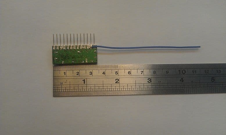
Click to zoom
Application Details
- Equipment Class
- DSS - Part 15 Spread Spectrum Transmitter
- Date of Grant
- Jan 26, 2014
- Application Purpose
- Original Equipment
- Date of Application
- Jan 26, 2014
- Equipment Note
- Intruder alarm
- Frequency Range
- 908.80000000 - 919.20000000
- Company
- Quatro Electronics Ltd
- Country
- United Kingdom
Documents & Files
Document Text
Text extracted from the exhibit documents filed with the FCC. Open a document above to read the original.
Users Manual
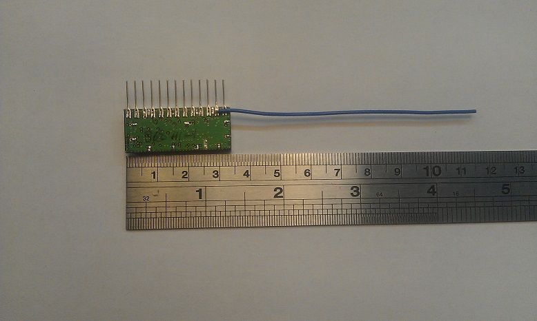
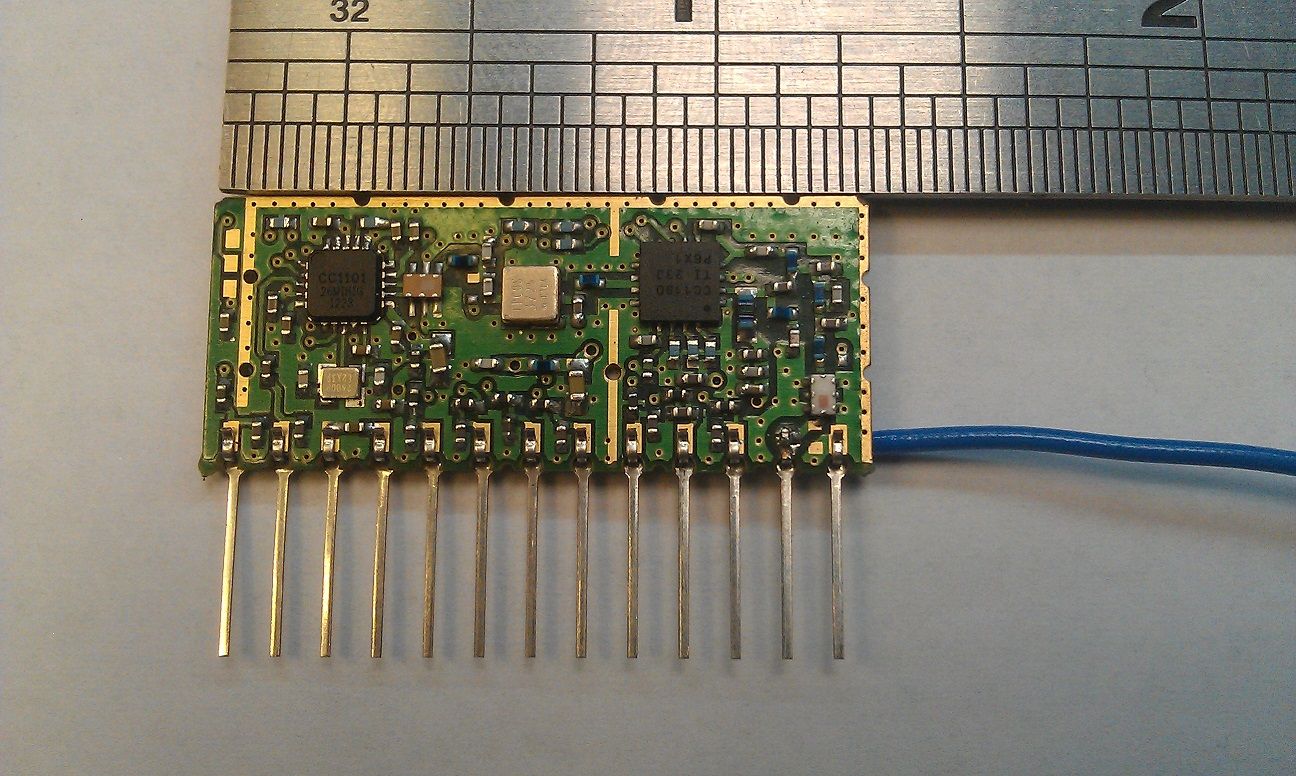
CONFIDENTIAL Issue B Page 1 of 4 20 th January 2014 Model # WDLM914HP Quatro Wireless Data Link Module (WDLM914HP) User Guide Introduction The Quatro Wireless Data Link Module (WDLM914HP) is a battery powered self- contained data transmitter receiver device, designed to give a long service life of up to 5 years in permanent installations dependent on battery size and application. This is achieved through careful power management techniques, ensuring that the transmitter and ancillary systems are turned off when not required to conserve the battery. The WDLM series of modules are used in a range of Quatro products to report sensor status to the monitoring receiver. When triggered, the transmitter uses a short transmission to alert the monitoring receiver that it has been activated. It also transmits its status periodically to the monitoring receiver as a ‘health’ check. The data to be transmitted can range from a simple event trigger to stream of status data. The WDLM series along with ancillary circuits are typically powered by a 3.6V Lithium cell for longest life, but other power sources are possible depending on application. For example multiple cells may be used to extend battery life still further. The WDLM device is embedded into a sensor, the entire device (WDLM and sensor) is then “learned” into the sensor monitor. The sensor is learned by presenting a magnet to the sensor. This sends the detector’s serial number in an encoded, short, low power transmission to the sensor monitor. The sensor’s serial number is the same as the sensors electronic address and is independent of the WDLM. Another WDLM device is used in the monitoring receiver. The WDLM relies on a matching processor which programs the WDLM with the desired radio frequency parameters such as RF output power, modulation parameters and frequency hopping method along with the data traffic to be transmitted. Configuring the radio link involves setting a number of registers in the transceiver chip via a serial connection in accordance with the Texas Instruments data to create the required mode and method of operation. CONFIDENTIAL Issue B Page 2 of 4 20 th January 2014 The parameters for operation are hard coded into the Quatro firmware and are not user accessible or changeable. This is to make sure the module remains FCC compliant. See reference 1 below for more detail about the Texas Instruments chipset used. Module Installation The module comes pre-installed in the device it is intended to inter-operate with, therefore the user should not tamper with, attempt to remove or otherwise interfere with the device. Doing so will invalidate the FCC certification and any implied warranty. NOTE – The transmitter must not be co-located or operated in conjunction with any other antenna or transmitter. This equipment complies with the FCC RF radiation exposure limits set forth for an uncontrolled environment. This equipment should be installed and operated with a minimum distance of 20cm between the radiator and any part of your body. Electrical / Mechanical Specifications The module is designed to be powered from the equipment into which it is installed and as such is dependent on it for power and control signals. For the sake of completeness the following outlines the modules key electrical specifications. DC Power requirement o 3.6V nominal (3.7V max) at up to 350mA, dependent on RF output power RF output power o Up to +26dBm (400mW), but limited by control firmware to meet Part 15 FCC regulations RF receive sensitivity o Typically better than -100dBm RF operating frequency o Capable of operating between 850 and 950MHz, but limited in firmware to meet Part 15 FCC regulations Operating and Storage temperatures o Storage temperature range -40C to + 80C o Operating temperature range -10C to +40C (Limited by equipment battery temperature range) Spurious emissions and receiver blocking CONFIDENTIAL Issue B Page 3 of 4 20 th January 2014 o FCC part 15 compliant Mechanical constraints Module size 34x5x14mm Installation by means of 13 pins on 2.4mm pitch Further technical information - is available in the document named “914P High Power Wireless Link Operational Description. Troubleshooting Guide There are no user serviceable parts within the WDLM series of devices or associated equipment. Please return the faulty unit to the Service Department, Head Office for testing and repair. Note, there are some simple system checks to validate correct operation that can be performed before the unit is returned to base. It is assumed the WDLM is embedded in a multi-function switch sensor and thus the following checks that not only the WDLM is operational but also the associated MFS is operating correctly. Others sensors which contain a WDLM may operate and learn in a different manner, but in general terms if a sensor is able to learn into a monitor the WDLM is functioning correctly. Conversely if a sensor is not able to learn into a monitor, the problem may lie with either the WDLM, associated processor, the sensor itself or the battery supply. It is not possible to identify the root cause without further detailed tests which are beyond the scope of this document. FAULT ACTION Sensor monitor receiver reports sensor ‘tampered’ o Check that the sensor is mounted vertically with the LEDs facing downwards. o Check that the enclosure is not damaged o With the sensor monitor in standby, open the door, wait 5 seconds, then close the door again. Sensor monitoring receiver reports the sensor ‘open’ o Check alignment of actuator and sensor. o With the sensor monitor in standby, open the door, wait 5 seconds, then close the door again. Sensor will not learn into the sensor monitor. o Tilt the unit to check that the yellow LED flashes indicating that the unit is powered on. o With the unit mounted vertically, place two magnetic keys on the sides of the unit and observe the two LEDs flash o While in walk test mode, place one magnet along the side o…
Text truncated - open the document above for the full version.
Cover Letter(s)
Quatro Electronics Ltd., Equipment Model Numbers which use XL8WDLM914HP PAU4000 PAU4000GPRS PAU4000GPRS PAU6000 PAU8000 SA4000 SA6000 SA8000 SA4001 SA6001 SA8001 SA4002 SA6002 SA8002 SAP6000 SAP8000 SAPC6000 SAPC8000 HOME4000 HOME6000 HOME8000 SMO4000 SMO6000 SMO8000 PIR4000 PIR6000 PIR8000 ICAM6000 ICAM8000 EPIR4000 EPIR6000 EPIR8000 ECAM6000 ECAM8000 MFS4000 MFS4001 MFS6000 MFS8000 RKP4000 RKP4000P RKP6000 RKP8000 RKP6000P RKP8000P RS4000B RS4000A RS6000B RS6000A RS8000A RS8000B DSIREN DSIREN8000 IS6000 IS8000 QE-VX402 QE-VX402-8000 G-VX402 G-VX402-8000 QE-BX80 QE-BX80-8000 G-BX80 G-BX80-8000 QE-HX40 QE-HX40-8000 H-HX40 H-HX40-8000 QE-HX80 QE-HX80-8000 G-HX80 G-HX80-8000 QE-FIT QE-FIT-8000 G-FIT G-FIT-8000 QE-PBS QE-PBS-8000 G-PBS G-PBS-8000 QE-SEA QE-SEA-8000 G-SEA G-SEA-8000 PDD-MFS4000 PDD-MFS6000 PDD-MFS8000 QE-PDD QE-PDD-8000 QE-RRE QE-RRE-8000 G-RRE G-RRE-8000 SA-MK8000 SA1-8000 SA2-8000 SA3-8000 TA1-8000 TA2-8000 TA3-8000 FA1-8000 FA2-8000 FA3-8000 VF1-8000 VF2-8000 VF3-8000
ID Label/Location Info
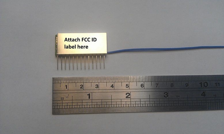
FCC ID : XL8WDLM914HP This device complies with part 15 of the FCC Rules. Operation is subject to the following two conditions: (1) This device may not cause harmful interference, and (2) this device must accept any interference received, including interference that may cause undesired operation.
Test Report
|---------- ( Cambridge Ltd. ) ----------| Testing EMCEMC Consultancy EMC Training or : 01223 241140 (accounts) 23, Headington Drive, Cambridge. CB1 9HE Tel : 01954 251974 (test site) Fax : 01954 251907 email: [email protected] web : www.dbtechnology.co.uk REPORT ON ELECTROMAGNETIC COMPATIBILITY TESTS Performed at: TWENTY PENCE TEST SITE Twenty Pence Road, Cottenham, Cambridge U.K. CB24 8PS on Quatro Electronics Ltd WDLM914HP dated 10th December 2013 Document History DBDSAdded radiated measurements below 30MHz 6,12,14,15,5422/01/143 PBDBFrequency hopping changed to DSS214/01/142 Initial release12/12/131 Approved by Revised by Description of modifications Affected page(s) DateIssue Based on report template: v090319 1 of 54 Page: Test Report T4651 Test No: FCC ID: XL8WDLM914HP R3295 3 Report No: Issue No: This report shall not be reproduced except in full, without the written approval of: dB Technology (Cambridge) Ltd. Equipment Under Test (EUT):WDLM914HP Test Commissioned by:Quatro Electronics Ltd Quatro House School Lane Lytham Lancashire FY8 5NL Representative:Tim Forrester Test Started:10th September 2013 Test Completed:21st November 2013 Test Engineer:Dave Smith Date of Report:10th December 2013 Written by:Dave SmithChecked by:Derek Barlow Signature:Signature: Date:10th December 2013Date:12th December 2013 dB Technology can only report on the specific unit(s) tested at its site. The responsibility for extrapolating this data to a product line lies solely with the manufacturer. Test Standards Applied CFR 47Code of Federal Regulations: Pt 15 Subpart C - Radio Frequency Devices - Intentional Radiators In particular, the rules of part 15.247 for digital spread spectrum (DSS) devices were applied. CFR 47Code of Federal Regulations: Pt 15 Subpart B- Radio Frequency Devices - Class BUnintentional Radiators 2 of 54 Page: Test Report T4651 Test No: FCC ID: XL8WDLM914HP R3295 3 Report No: Issue No: This report shall not be reproduced except in full, without the written approval of: dB Technology (Cambridge) Ltd. Emissions Test Results Summary CFR 47 - Subpart CPASS TestPortMethodLimitPASS/FAILNotes Conductedac powerANSI C63.4:2003 15.207N/A#1 Emissions Radiated ANSI C63.4:2003 15.209PASS Emissions Occupied DA 00-705 15.247 (a)(1)(i)PASS Bandwidth Channel DA 00-705 15.247 (a)(1)PASS Separation No. of Hopping DA 00-705 15.247 (a)(1)(i)PASS Channels Time of DA 00-705 15.247 (a)(1)(i)PASS Occupation Peak Output DA 00-705 15.247 (b)(2)PASS Power ConductedAntennaDA 00-705 15.247 (d)PASS Spurious specs_fccv100412 CFR 47 - Subpart BPASS TestPortMethodLimitPASS/FAILNotes Conductedac powerANSI C63.4:2003 FCC_BN/A#1 Emissions conducted Radiated ANSI C63.4:2003 FCC_BPASS Emissions radiated specs_fccv100412 #1Test not applicable because the radio module will only be used in battery powered products. 3 of 54 Page: Test Report T4651 Test No: FCC ID: XL8WDLM914HP R3295 3 Report No: Issue No: This report shall not be reproduced except in full, without the written approval of: dB Technology (Cambridge) Ltd. Contents 48 PLOT 27 Conducted Antenna - Spurious Emissions - 1GHz to 5GHz - Fixed Freq. . . . . . . . . . . . . . . . . . . 47 PLOT 26 Conducted Antenna - Spurious Emissions - 850MHz to 1GHz Fixed Freq. . . . . . . . . . . . . . . . . . 46 PLOT 25 Conducted Antenna - Spurious Emissions - 9kHz to 1GHz - Fixed Freq. . . . . . . . . . . . . . . . . . . 45 PLOT 24 Conducted Antenna - Spurious Emissions - High Channel Band Edge . . . . . . . . . . . . . . . . . . . . 44 PLOT 23 Conducted Antenna - Spurious Emissions - Low Channel Band Edge . . . . . . . . . . . . . . . . . . . . . 43 PLOT 22 Conducted Antenna - Peak Power - High Channel . . . . . . . . . . . . . . . . . . . . . . . . . . . . . . . . . . . . 42 PLOT 21 Conducted Antenna - Peak Power - Mid Channel . . . . . . . . . . . . . . . . . . . . . . . . . . . . . . . . . . . . . 41 PLOT 20 Conducted Antenna - Peak Power - Low Channel . . . . . . . . . . . . . . . . . . . . . . . . . . . . . . . . . . . . 40 PLOT 19 Conducted Antenna - Channel Repetition Time - Short Data Sequence . . . . . . . . . . . . . . . . . . . . 39 PLOT 18 Conducted Antenna - Channel Repetition Time - Long Data Sequence . . . . . . . . . . . . . . . . . . . . 38 PLOT 17 Conducted Antenna - Channel Dwell Time - Short Pulse Data Sequence . . . . . . . . . . . . . . . . . . 37 PLOT 16 Conducted Antenna - Channel Dwell Time - Long Duration Data Sequence . . . . . . . . . . . . . . . 36 PLOT 15 Conducted Antenna - Number of Channels - Part 2 of 2 . . . . . . . . . . . . . . . . . . . . . . . . . . . . . . . . 35 PLOT 14 Conducted Antenna - Number of Channels - Part 1 of 2 . . . . . . . . . . . . . . . . . . . . . . . . . . . . . . . . 34 PLOT 13 Conducted Antenna - Channel Separation . . . . . . . . . . . . . . . . . . . . . . . . . . . . . . . . . . . . . . . . . . . 33 PLOT 12 Conducted Antenna - 20dB Bandwidth - High Channel . . . . . . . . . . . . . . . . . . . . . . . . . . . . . . . . 32 PLOT 11 Conducted Antenna - 20dB Bandwidth - Mid Channel . . . . . . . . . . . . . . . . . . . . . . . . . . . . . . . . 31 PLOT 10 Conducted Antenna - 20dB Bandwidth - Low Channel . . . . . . . . . . . . . . . . . . . . . . . . . . . . . . . . 30 PLOT 9 Radiated Emissions - Rx - 5GHz to 10GHz . . . . . . . . . . . . . . . . . . . . . . . . . . . . . . . . . . . . . . . . . . . 29 PLOT 8 Radiated Emissions - Rx - 2GHz to 5GHz . . . . . . . . . . . . . . . . . . . . . . . . . . . . . . . . . . . . . . . . . . . . 28 PLOT 7 Radiated Emissions - Rx - 1GHz to 2GHz . . . . . . . . . . . . . . . . . . . . . . . . . . . . . . . . . . . . . . . . . . . . 27 PLOT 6 Radiated Emissions - Rx - 25MHz to 1GHz . . . . . . . . . . . . . . . . . . . . . . . . . . . . . . . . . . . . . . . . . . . 26 PLOT 5 Radiated Emissions - Tx - 5GHz to 10GHz . . . . . . . . . . . . . . . . . . . . . . . . . . . . . . . . . . . . . . . . . . . 25 PLOT 4 Radiated Emissions - Tx - 2GHz to 5GHz . . . . . . . . . . . . . . . . .…
Text truncated - open the document above for the full version.
Test Setup Photos
|---------- ( Cambridge Ltd. ) ----------| Testing EMCEMC Consultancy EMC Training or : 01223 241140 (accounts) 23, Headington Drive, Cambridge. CB1 9HE Tel : 01954 251974 (test site) Fax : 01954 251907 email: [email protected] web : www.dbtechnology.co.uk REPORT ON ELECTROMAGNETIC COMPATIBILITY TESTS Performed at: TWENTY PENCE TEST SITE Twenty Pence Road, Cottenham, Cambridge U.K. CB24 8PS on Quatro Electronics Ltd WDLM914HP dated 10th December 2013 Document History DBDSAdded radiated measurements below 1GHz 522/01/132 Initial release12/12/131 Approved by Revised by Description of modifications Affected page(s) DateIssue Based on report template: v090319 1 of 5 Page: Test Report Photos T4651 Test No: FCC ID: XL8WDLM914HP R3295 2 Report No: Issue No: This report shall not be reproduced except in full, without the written approval of: dB Technology (Cambridge) Ltd. Photograph 1 Radiated Emissions Photograph 2 Radiated Emissions 2 of 5 Page: Test Report Photos T4651 Test No: FCC ID: XL8WDLM914HP R3295 2 Report No: Issue No: This report shall not be reproduced except in full, without the written approval of: dB Technology (Cambridge) Ltd. Photograph 3 Radiated Emissions Photograph 4 Radiated Emissions 3 of 5 Page: Test Report Photos T4651 Test No: FCC ID: XL8WDLM914HP R3295 2 Report No: Issue No: This report shall not be reproduced except in full, without the written approval of: dB Technology (Cambridge) Ltd. Photograph 5 Radiated Emissions Photograph 6 Conducted Antenna 4 of 5 Page: Test Report Photos T4651 Test No: FCC ID: XL8WDLM914HP R3295 2 Report No: Issue No: This report shall not be reproduced except in full, without the written approval of: dB Technology (Cambridge) Ltd. Photograph 7 Radiated Emissions below 30MHz Photograph 8 Radiated Emissions below 30MHz 5 of 5 Page: Test Report Photos T4651 Test No: FCC ID: XL8WDLM914HP R3295 2 Report No: Issue No: This report shall not be reproduced except in full, without the written approval of: dB Technology (Cambridge) Ltd.
Contact Information
Applicant
Tom Barnard(Managing Director)
Test Firm
DB TechnologyDave Smith
Technical Specifications
| # | Rule Parts | Frequency Range | Power Output |
|---|---|---|---|
| 1 | 15C | 908.8 MHz - 919.2 MHz | 160.00 mW |
Other Applications from Quatro Electronics Ltd
XL8EXTPIR1501
Mar 11, 2012EXTERNAL PIR SENSORS
Equipment Class
DSC - Part 15 Security/Remote Control Transmitter
XL8SIREN1501
Mar 11, 2012EXTERNAL SIREN
Equipment Class
DSC - Part 15 Security/Remote Control Transmitter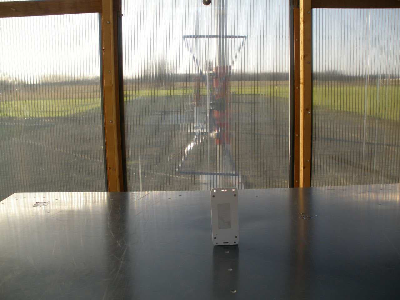
XL8KEY1500
Feb 12, 2012WIRELESS KEYPAD
Equipment Class
DSC - Part 15 Security/Remote Control Transmitter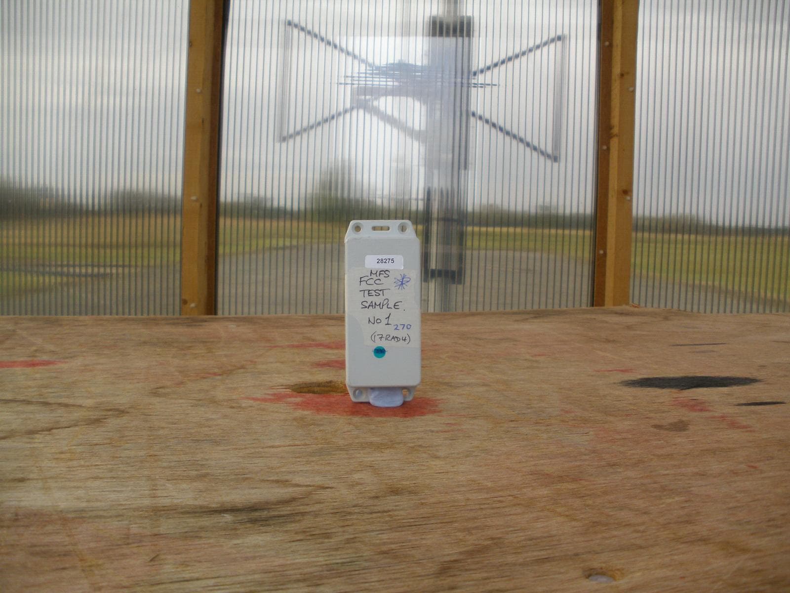
XL8MFS1501
Sep 19, 2010WIRELESS MULTI-FUNCTION SENSOR
Equipment Class
DSC - Part 15 Security/Remote Control Transmitter
XL8SMOKE1501
Apr 28, 2010WIRELESS SMOKE DETECTOR
Equipment Class
DSC - Part 15 Security/Remote Control Transmitter