XLY-2455SPRFID&KEYPAD LOCKER LOCK
Zephyrlock,LLC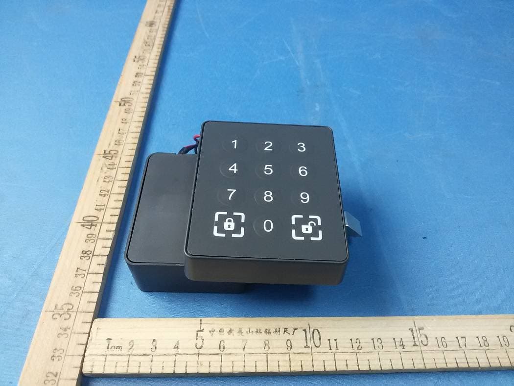
Click to zoom
Application Details
- Equipment Class
- DXX - Part 15 Low Power Communication Device Transmitter
- Date of Grant
- Sep 20, 2015
- Application Purpose
- Original Equipment
- Date of Application
- Sep 20, 2015
- Equipment Note
- RFID&KEYPAD LOCKER LOCK
- Frequency Range
- 13.56000000 - 13.56000000
- Company
- Zephyrlock,LLC
- Country
- United States
Documents & Files
Document Text
Text extracted from the exhibit documents filed with the FCC. Open a document above to read the original.
Users Manual
1 / 6 2455SP USER MANUAL 1. Summary 1.1 What is 2455SP Locks? 2455SP locks are the RFID and keypad integrated locker lock can operated by either RFID Cards or password keypads. Digital Button (0 – 9) Lock Button Unlock Button 2 / 6 1.2 RFID Card Types and Functions Item Card Types Functions 1 User Card This card can open registered lock only 2 Data Card Read the open lock record and lock information 3 Time Change Card Setup lock clock 4 Setup Card Write preset information into lock 5 Management Card Open any lock does not clear the registered card/password 6 Control Card ➊ Open any lock ➋ Clear registered card/password 7 Authorization Card Authorize ELMS software and locks 1.3 Lock Operation System Composition Lock Operation System consisted of PC based Electronic Lock Management System (ELMS) software and RFID Card reader/writer, and enable the operator to issue User card, setting the lock information, lock status and to produce the statistical report. System Requirements: * OS: Windows XP/Windows7/Windows8 * USB port for Card reader/writer interface 3 / 6 2. Operation Type 2455SP Locker Locks are designed to work for the various operation requirements by simple setup process. Following operation modes can be programmed before or after lock installation. 2.1 Shared Use Mode 2.1.1 User can select any available locker 2.1.2 LED lamp to show the status of locks 2.1.3 Programmable to use multiple locks with one user card 2.1.4 Programmable for time based operation 2.2 Permanent Use Mode 2.2.1 Locker assigned to each user card in advance 2.2.2 Programmable to use multiple assigned lockers with one card 2.2.3 Programmable for multiple user per a locker 4 / 6 3. Lock Operations 3.1 Shared Use Mode ‐‐ Storage Device(s) 3.1.1 User approaches the locker, Unlock Button is glowing green, which means the locker is available 3.1.2 Presses the Unlock Button, Green LED starts flashing the solenoid retracts for 3 seconds 3.1.3 User opens the locker door within 3 seconds, places device(s) inside the locker, then closes the door 3.1.4 User th en refocuses on the keypad and begins entering his own 4‐digit secret code 3.1.5 As he presses the first number button, the green LED flashing turns off, Red LED Successively turns on 3.1.6 After the fourth number is entered, the Lock Button starts flashing red 3.1.7 Presses the Lock But ton within 5 seconds 3.1.8 The Lock Button continues to glow red, showing that the locker is in use ‐‐ Ta ke Device(s) 3.1.9 User approaches the locker, start enter the 4‐digit secret code then press Unlock Button 3.1.10 Red LED turns off, Green LED turns on 3.1.11 User opens the locker door and take out his device(s) then closes the locker door 3.1.12 Unlock Button light now glow steady green to show th e locker is available now, waiting for the next user 3.2 Permanent Use Mode 3.2.1 The Lock Button glow red, showing that the locker is in use 3.2.2 User approaches the locker, Swipe registered User Card 3.2.3 Red LED turns off, Green LED starts flashing the solenoid retracts for 3 seconds 3.2.4 User opens the locker door within 3 seconds, places (or take) device(s) then closes the lock er door 3.2.5 After 5 seconds, Green LED turns off, Red LED turns on, showing that the locker is in use 5 / 6 4. Lock Setting and Emergency open 4.1 Lock Setting 4.1.1 Use the ELMS software to pre‐setting the lock’s information, then issues Cards 4.1.2 Swipe Authorization Card 4.1.3 Swipe Setup Card, Lock setting finished 4.2 Emergency open In case user forgot the password, or lost his User card 4.2.1 Operator can swipe the Management Card to open the lock 4.2.2 Or swipe the Control Card to open the lock Note: If the lock worked in Shared Use mode, after swiped the Control Card, the registered card / password will be cle ar 6 / 6 5. Indication of sound and light 5.1 Keypad operation 5.1.1 All the secret code is 4‐digit 0 – 9 5.1.2 Key tone: 1 short beep 5.1.3 Unlock or Lock : 2 short beeps 5.1.4 Less than 4‐digit are entered presses Lock Button: 4 short beeps 5.1.5 More than 4‐digit are entered presses Lock Button: 3 short beeps 5.1.6 A vailable status: Unlock Button glow green 5.1.7 In use status: Lock Button glow red 5.2 RFID Card operation 5.2.1 Swipe User Card: 1 short beep, green LED flashing 5 seconds 5.2.2 Swipe Management Card: 2 short beeps, green LED flashing 5 seconds 5.2.3 Swipe Control Card: 2 short beeps, green LED flashing 5 seconds 5.2.4 Swipe Data Card: Start Read: 1 short beep, Finished: 2 short beeps green LED fla shing 5.2.5 Swipe Time Change Card: 2 short beeps 5.2.6 Swipe Setup Card: 2 short beeps 5.2.7 Swipe Authorization Card: 1 short beeps FCC Information and Copyright This equipment has been tested and found to comply with the limits for a Class B digital device, pursuant to part 15 of the FCC Rules. These limits are designed to provide reasonable protection against harmful interference in a residential installation. This equipment generates, uses and can radiate radio frequency energy and, if not installed and used in accordance with the instructions, may cause harmful interference to radio communications. However, there is no guarantee that interference will not occur in a particular installation. If this equipment does cause harmful interference to radio or television reception, which can be determined by turning the equipment off and on, the user is encouraged to try to correct the interference by one or more of the following measures: —Reorient or relocate the receiving antenna. —Increase the separation between the equipment and receiver. —Connect the equipment into an outlet on a circuit different from that to which the receiver is connected. —Consult the dealer or an experienced radio/TV technician for help. 15.19 Labelling requirements. This device complies with part 15 of the FCC Rules. Operation is subject to the following two conditions: (1)This device may not cause harmful interference, and (2) this device must accept any interference received, including interferen…
Text truncated - open the document above for the full version.
Cover Letter(s)
SCS-F18: Project and Product Certification Representative Authorization Letter Page 1 of 2 Rev 5.0 775 Montague Expressway Milpitas, CA 95035 Tel: 408-526-1188 Fax: 408-526-1088 Email: [email protected] Project and Product Certification Representative Authorization Letter Reason for Amendment (current / obsolete) Revision History Approved Date From To Initial Release (obsolete) 1.0 1.0 Nov-14-2006 Revised wording (obsolete) 1.0 2.0 Sept–25-2007 Updated company template (obsolete) 2.0 3.0 Jan-31-2012 Updated letter information (obsolete) 3.0 4.0 May-23-2014 Added FCC ID field (current) 4.0 5.0 Sept 16 2014 SCS-F18: Project and Product Certification Representative Authorization Letter Page 2 of 2 Rev 5.0 Zephyrlock,LLC 2015/09/15 To: SIEMIC, INC. 775 Montague Expressway, Milpitas, CA 95035 USA Dear Sir/Madam, Re: Product Certification Representative Authorization Letter We, ___ Zephyrlock,LLC _hereby authorize SIEMIC, Inc. to act as a Certification Body for certifying for the following project(s): Product: RFID&KEYPAD LOCKER LOCK Trade Name: N/A Model Name: 2455SP Serial Model: N/A FCC ID: XLY-2455SP Sincerely, Client’s name / title : Kenvin Houlihan / Manager Contact information / address : 14 Finance Drive, Danbury, Connecticut, United States 06810
Cover Letter(s)
SCS-F19: Confidentiality Request Letter Page 1 of 2 Rev 4.0 775 Montague Expressway Milpitas, CA 95035 Tel: 408-526-1188 Fax: 408-526-1088 Email: [email protected] Confidentiality Request Letter Reason for Amendment (current / obsolete) Revision History Approved Date From To Initial Release (obsolete) 1.0 1.0 Nov-14-2006 Adding CFR 2.459 (obsolete) 1.0 2.0 August – 11 - 2008 Updated company template & Added text box (obsolete) 2.0 3.0 Jan-31-2012 Added IC confidentiality letter form (current) 3.0 4.0 March-26-2015 SCS-F19: Confidentiality Request Letter Page 2 of 2 Rev 4.0 Zephyrlock,LLC 2015/09/15 To: Federal Communications Commission Authorization and Evaluation Division 7435 Oakland Mills Road Columbia, MD Subject: Permanent Confidentiality Request for FCC ID: XLY-2455SP We hereby request confidential treatment of information accompanying this application as outlined below: - . Block Diagram - Schematics - Operational Description The above materials contain trade secrets and proprietary information not customarily released to the public. The public disclosure of these materials may be harmful to the applicant and provide unjustified benefits to its competitors. The applicant understands that pursuant to Section 0.457 & 0.459 of the Rules, disclosure of this application and all accompanying documentation will not be made before the date of the Grant for this application. Sincerely, Client’s name / title : Kenvin Houlihan / Manager Contact information / address : 14 Finance Drive, Danbury, Connecticut, United States 06810
External Photos
APPENDIX-PHOTOGRAPHS OF EUT CONSTRUCTIONAL DETAILS Photo 1 Photo 2 Photo 3 Photo 4 Photo 5 Photo 6
ID Label/Location Info
FCC ID LABELING AND LOCATION FCC ID Label FCC ID Label Location The label shown shall be permanently affixed at a conspicuous location on the device and be readily visible to the user at the time purchase (Labeling requirements per 2.925)
Internal Photos
APPENDIX-PHOTOGRAPHS OF EUT CONSTRUCTIONAL DETAILS Photo 1 Photo 2 Photo 3 Photo 4 ANT Photo 5
Test Setup Photos
Page 26 of 27 Report No.:NTEK-2015NT0817531F ` 7. EUT TEST PHOTO Radiated Measurement Photos Page 27 of 27 Report No.:NTEK-2015NT0817531F ` Conducted Measurement Photos
Contact Information
Applicant
Kenvin Houlihan(engineer)
Test Firm
Shenzhen NTEK Testing Technology Co., Ltd.Jason Chen
Technical Specifications
| # | Rule Parts | Frequency Range | Power Output |
|---|---|---|---|
| 1 | 15C | 13.56 MHz - 13.56 MHz | - |