XM4HT21014Remote control
Shanghai Height Electronics Co., Ltd.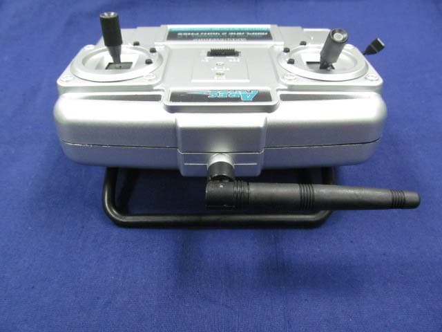
Click to zoom
Application Details
- Equipment Class
- DXT - Part 15 Low Power Transceiver, Rx Verified
- Date of Grant
- Feb 20, 2012
- Application Purpose
- Original Equipment
- Date of Application
- Feb 20, 2012
- Equipment Note
- Remote control
- Frequency Range
- 2404.00000000 - 2474.00000000
- Country
- China
Documents & Files
Document Text
Text extracted from the exhibit documents filed with the FCC. Open a document above to read the original.
Users Manual
2.4G four-channel rational remote controller Feature: Frequency: 2400MHZ - 2483MHZ adaptive (automatically start the search interfere with the smallest channel) Mode: DSM2 (automatic two-carrier frequency hopping, the frequency interval 40MHz. Modulation: FSK Operation: the ratio of four-channel remote control Description: The 2.4G four-channel rational remote controller is based on ISM 2.4G Hz frequency band. It has four control values. Just loading cell, open the power switch, the transmitter automatically search channels with the same ID CODE receiver to complete confirmation. Federal Communications Commission Statement This device complies with FCC Rules Part 15. Operation is subject to the following two conditions: ‧ This device may not cause harmful interference, and ‧ This device must accept any interference received, including interference that may cause undesired operation. ‧ This equipment has been tested and found to comply with the limits for a class B digital device, pursuant to Part 15 of the Federal Communications Commission (FCC) rules. These limits are designed to provide reasonable protection against harmful interference in a residential installation. This equipment generates, uses, and can radiate radio frequency energy and, if not installed and used in accordance with the instructions, may cause harmful interference to radio communications. However, there is no guarantee that interference will not occur in a particular installation. If this equipment does cause harmful interference to radio or television reception, which can be determined by turning the equipment off and on, the user is encouraged to try to correct the interference by one or more of the following measures: ‧ Reorient or relocate the receiving antenna. ‧ Increase the separation between the equipment and receiver. ‧ Connect the equipment into an outlet on a circuit different from that to which the receiver is connected. ‧ Consult the dealer or an experienced radio/TV technician for help. The use of a shielded-type power cord is required in order to meet FCC emission limits and to prevent interference to the nearby radio and television reception. It is essential that only the supplied power cord be used. Use only shielded cables to connect I/O devices to this equipment. You are cautioned that changes or modifications not expressly approved by the party responsible for compliance could void your authority to operate the equipment. Note: Any changes or modifications not expressly approved by the grantee of this device could void the user's authority to operate the equipment. RF exposure warning This equipment complies with FCC radiation exposure limits set forth for an uncontrolled environment. This equipment must be installed and operated in accordance with provided instructions and the antenna(s) used for this transmitter must be installed to provide a separation distance of at least 20 cm from all persons and must not be co-located or operating in conjunction with any other antenna or transmitter. End-users and installers must be provided with antenna installation instructions and transmitter operating conditions for satisfying RF exposure compliance.
External Photos
1. Appendix 2 – EUT Photograph (1) EUT Photo (2) EUT Photo (3) EUT Photo (4) EUT Photo (5) EUT Photo (6) EUT Photo
ID Label/Location Info
Model:HT21014 FCC ID: XM4HT21014 This device complies with Part 15 of the FCC Rules. Operation is subject to the following two conditions: (1) this device may not cause harmful interference, and (2) this device must accept any interference received, including interference that may cause undesired operation. The size of the label is 3cm*1.5cm.
Internal Photos
(1) EUT Photo (2) EUT Photo Report No: 11CS043R-RF-US-P06V01 Page: 2 of 2 (3) EUT Photo (4) EUT Photo
Test Report
Test Report FCC Part15.249 Product Name : Remote control Model No. : HT21014 FCC ID : XM4HT21014 Applicant : Shanghai Height electronics Co LTD Address : 1500 Huiren Road Jiading Shanghai China Date of Receipt : 14/12/2011 Test Date : 14/12/2011 ~ 13/01/2012 Issued Date : 07/02/2012 Report No. : 11CS043R-RF-US-P06V01 Report Version : V2.2 The test results relate only to the samples tested. The test results shown in the test report are traceable to the national/international standard through the calibration of the equipment and evaluated measurement uncertainty herein. This report must not be used to claim product endorsement by TAF, NVLAP or any agency of the Government. The test report shall not be reproduced except in full without the written approval of QuieTek Corporation. Report No: 11CS043R-RF-US-P06V01 Page: 2 of 35 Test Report Certification Issued Date : 07/02/2012 Report No. : 11CS043R-RF-US-P06V01 Product Name : Remote control Applicant : Shanghai Height electronics Co LTD Address : 1500 Huiren Road Jiading Shanghai China Manufacturer : Shanghai Height electronics Co LTD Address : 1500 Huiren Road Jiading Shanghai China Model No. : HT21014 FCC ID : XM4HT21014 EUT Voltage : DC 6.0V(4*AA batteries) Trade Name : Height Applicable Standard : FCC CFR Title 47 Part 15 Subpart C: 2008 ANSI C63.4: 2009 Test Result : Complied Performed Location : Suzhou EMC Laboratory No.99 Hongye Rd., Suzhou Industrial Park Loufeng Hi-Tech Development Zone., Suzhou, China TEL: +86-512-6251-5088 / FAX: +86-512-6251-5098 FCC Registration Number: 800392 Documented By : (Engineering ADM: Alice Ni) Reviewed By : (Senior Engineer: Jame Yuan) Approved By : (Engineering Manager: Marlin Chen) Report No: 11CS043R-RF-US-P06V01 Page: 3 of 35 Laboratory Information We, QuieTek Corporation, are an independent EMC and safety consultancy that was established the whole facility in our laboratories. The test facility has been accredited/accepted(audited or listed) by the following related bodies in compliance with ISO 17025, EN 45001 and specified testing scope: The related certificate for our laboratories about the test site and management system can be downloaded from QuieTek Corporation’s Web Site : http://www.quietek.com/tw/emc/accreditations/accreditations.htm The address and introduction of QuieTek Corporation’s laboratories can be founded in our Web site : http://www.quietek.com/ If you have any comments, Please don’t hesitate to contact us. Our contact information is as below: HsinChu Testing Laboratory : No.75-2, 3rd Lin, Wangye Keng, Yonghxing Tsuen, Qionglin Shiang, Hsinchu County 307, Taiwan, R.O.C. TEL:+886-3-592-8858 / FAX:+886-3-592-8859 E-Mail : [email protected] LinKou Testing Laboratory : No. 5-22, Ruei-Shu Valley, Ruei-Ping Tsuen, Lin-Kou Shiang, Taipei, Taiwan, R.O.C. TEL : 886-2-8601-3788 / FAX : 886-2-8601-3789 E-Mail : [email protected] Suzhou (China) Testing Laboratory : No. 99 Hongye Rd., Suzhou Industrial Park Loufeng Hi-Tech Development Zone., Suzhou,China. TEL : +86-512-6251-5088 / FAX : +86-512-6251-5098 E-Mail : [email protected] Taiwan R.O.C. :BSMI, NCC, TAF Germany :TUV Rheinland Norway :Nemko, DNV USA :FCC, NVLAP Japan :VCCI Report No: 11CS043R-RF-US-P06V01 Page: 4 of 35 TABLE OF CONTENTS Description Page 1. General Information....................................................................................................5 1.1. EUT Description .........................................................................................................5 1.2. Mode of Operation .....................................................................................................7 1.3. Tested System Details................................................................................................8 1.4. Configuration of Tested System .................................................................................9 1.5. EUT Exercise Software ............................................................................................10 2. Technical Test........................................................................................................... 11 2.1. Summary of Test Result ........................................................................................... 11 2.2. Test Environment.....................................................................................................12 3. Conducted Emission................................................................................................13 3.1. Test Equipment ........................................................................................................13 3.2. Test Setup ................................................................................................................13 3.3. Limit..........................................................................................................................14 3.4. Test Procedure.........................................................................................................14 3.5. Uncertainty ...............................................................................................................14 3.6. Test Result...............................................................................................................14 4. Radiated Emission...................................................................................................15 4.1. Test Equipment ........................................................................................................15 4.2. Test Setup ................................................................................................................16 4.3. Limit..........................................................................................................................17 4.4. Test Procedure.........................................................................................................18 4.5. Uncertainty ..................................................…
Text truncated - open the document above for the full version.
Test Setup Photos
1. Test Setup Photograph Description: Radiated Emission Test Setup for Below 1GHz Description: Radiated Emission Test Setup for Above 1GHz Description: Radiated Emission Test Setup for Above 18GHz
Contact Information
Applicant
Zhu Jie(Manager)
Test Firm
DEKRA Testing and Certification (Suzhou) Co., Ltd.Jerry Pan
Technical Specifications
| # | Rule Parts | Frequency Range | Power Output |
|---|---|---|---|
| 1 | 15C | 2.40 GHz - 2.47 GHz | - |