XMG-STM112C315 MHz TRANSMITTER
Echoflex Solutions Inc.
Click to zoom
Application Details
- Equipment Class
- DSC - Part 15 Security/Remote Control Transmitter
- Date of Grant
- Jul 19, 2010
- Application Purpose
- Original Equipment
- Date of Application
- Jul 14, 2010
- Equipment Note
- 315 MHz TRANSMITTER
- Frequency Range
- 315.00000000 - 315.00000000
- Company
- Echoflex Solutions Inc.
- Country
- Canada
Documents & Files
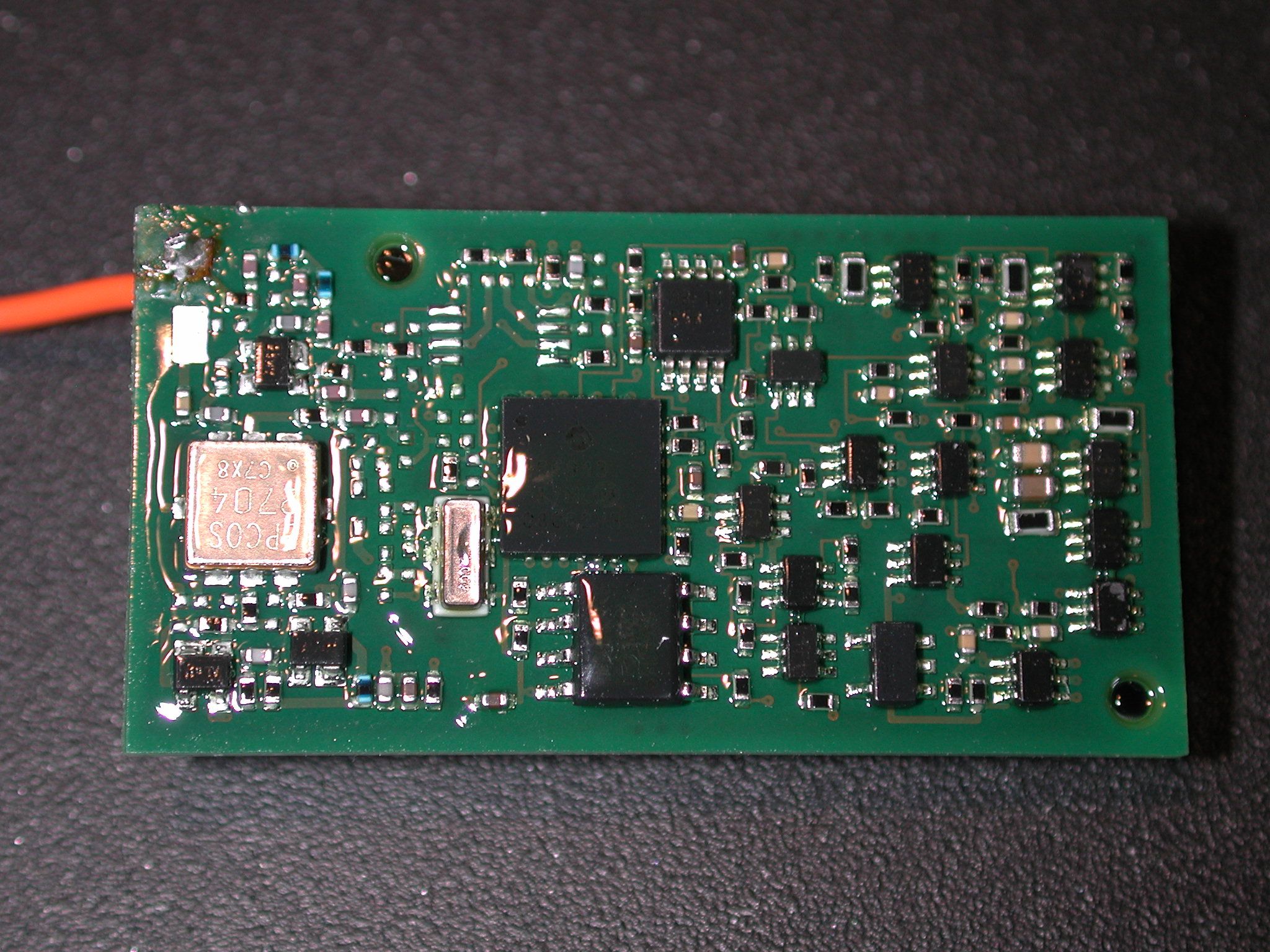
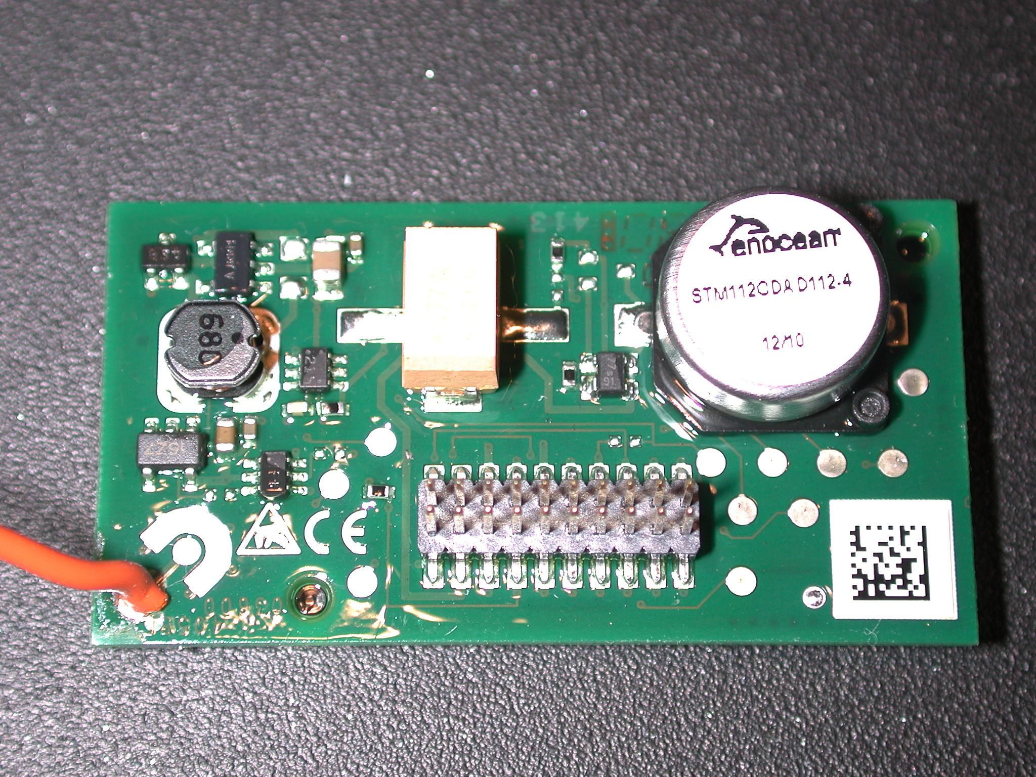
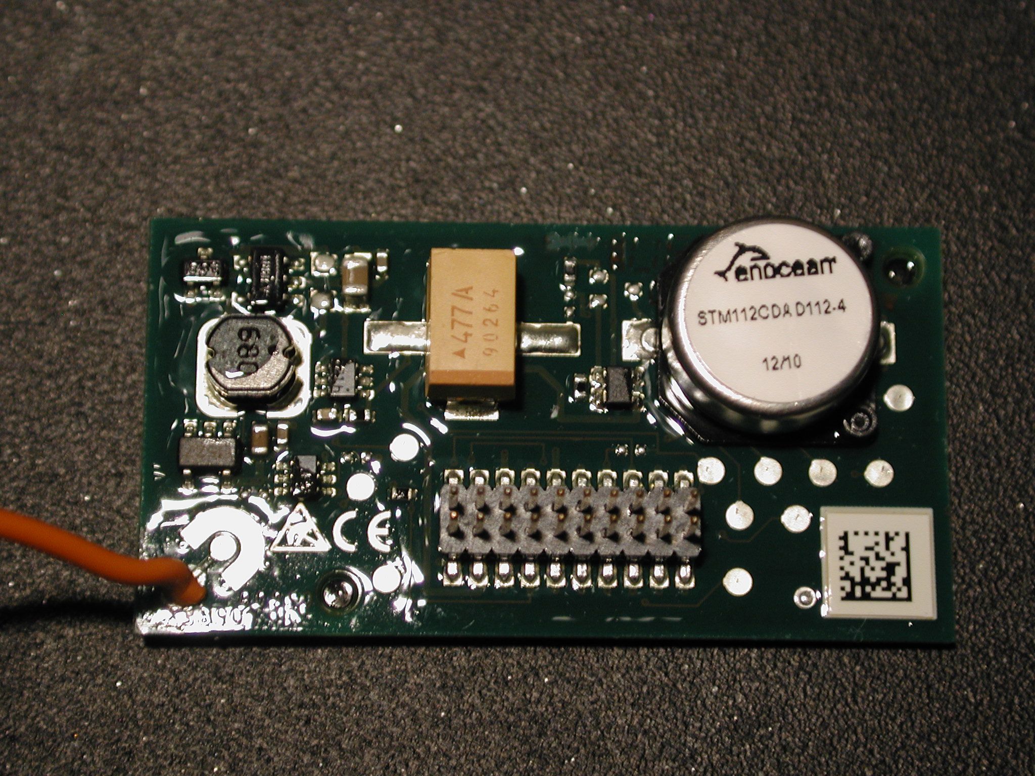
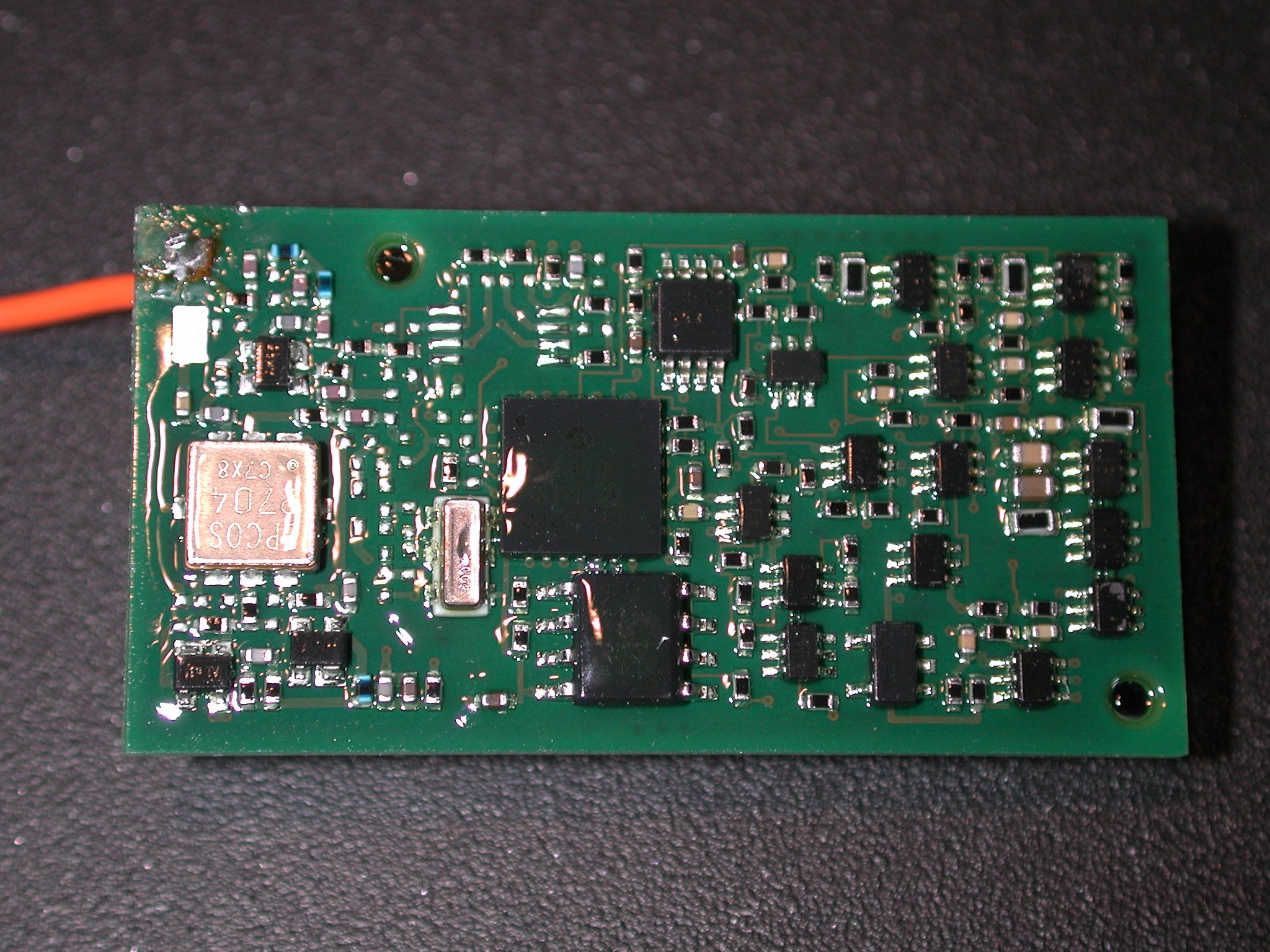
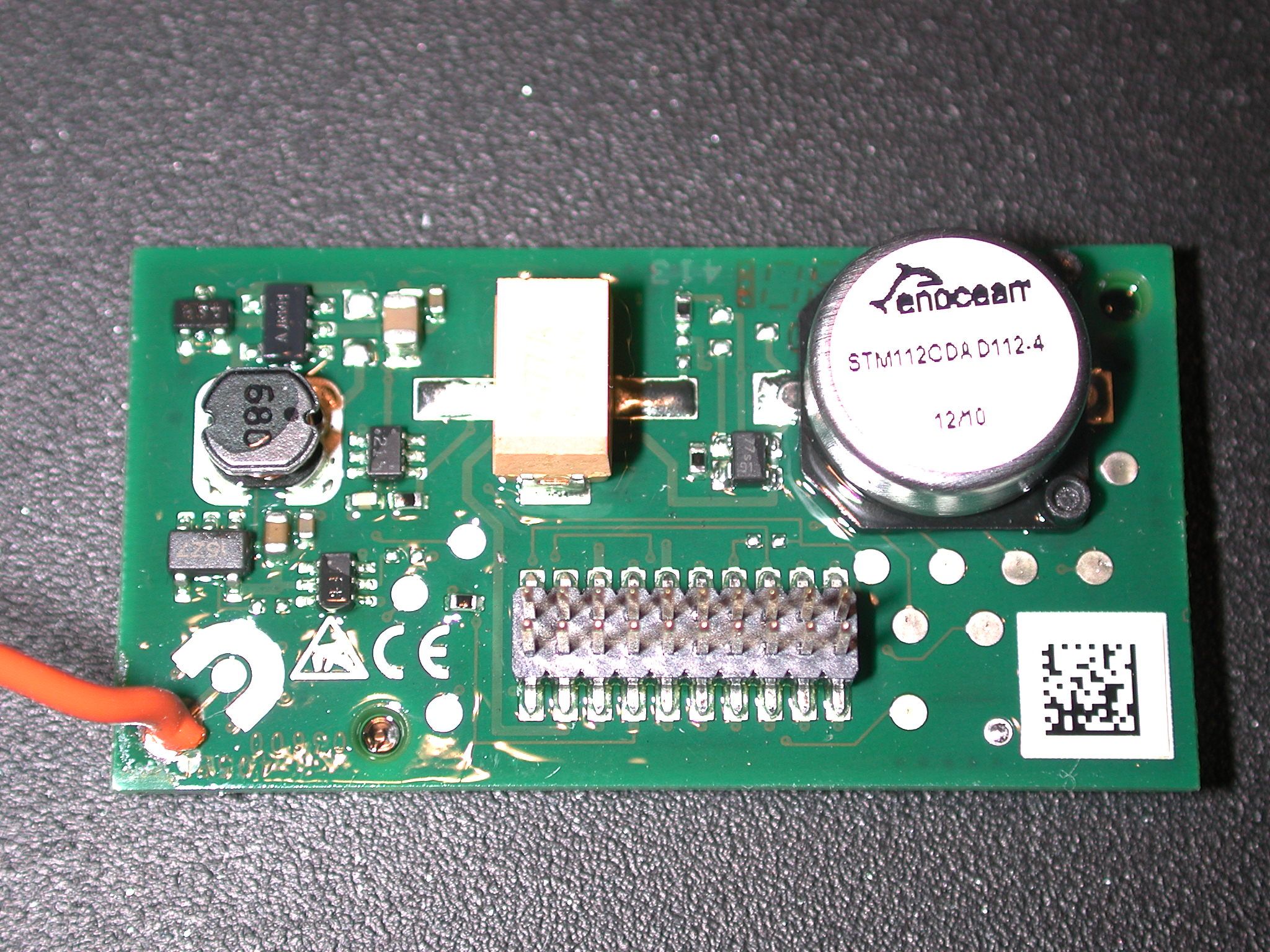
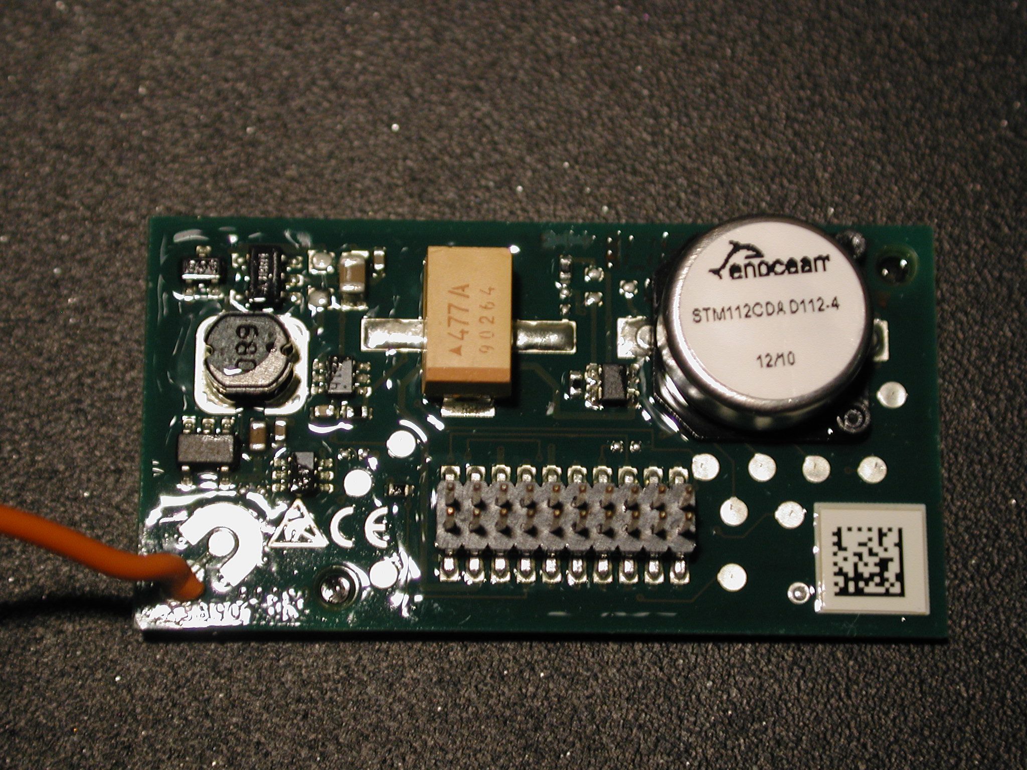
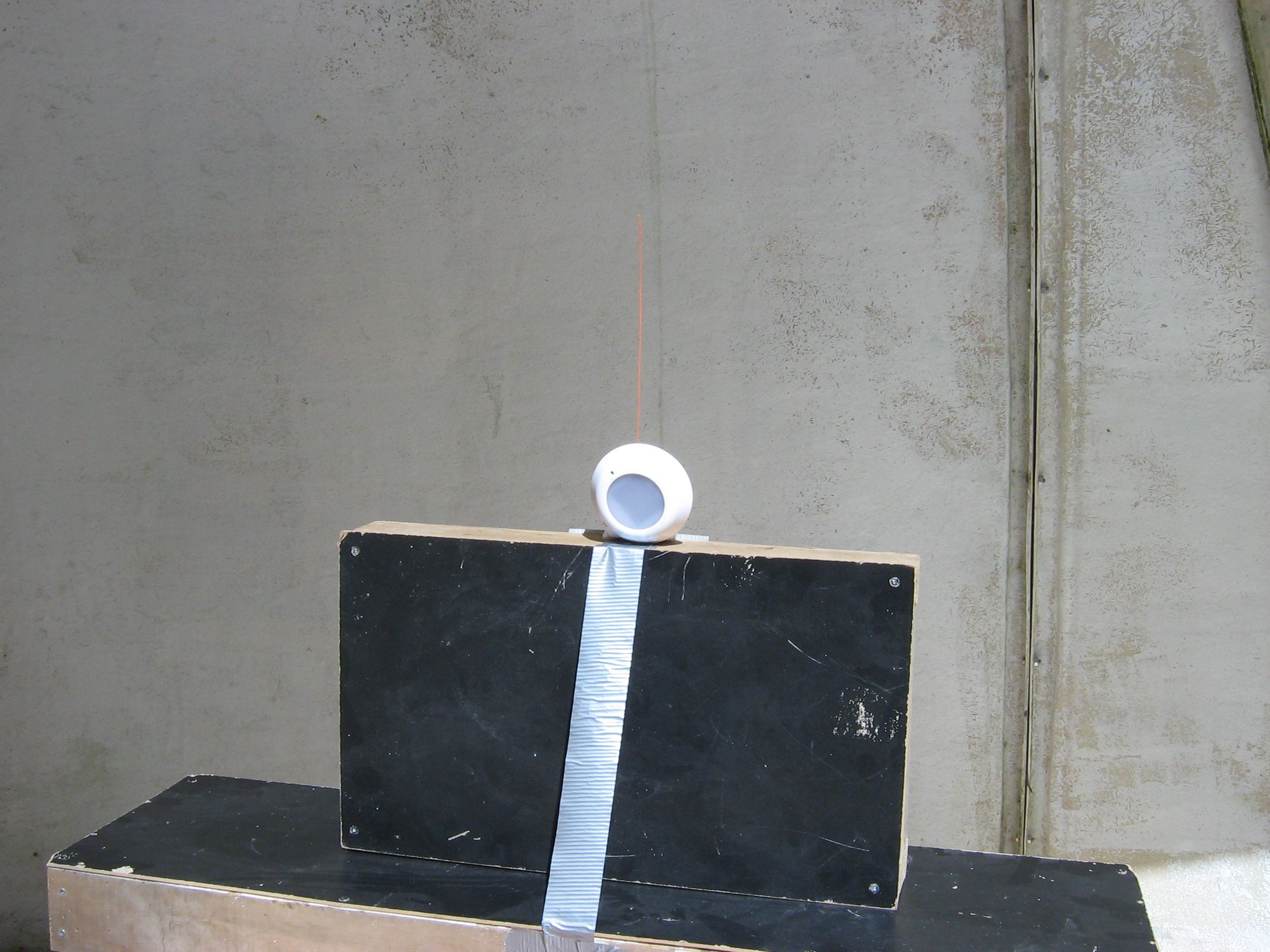

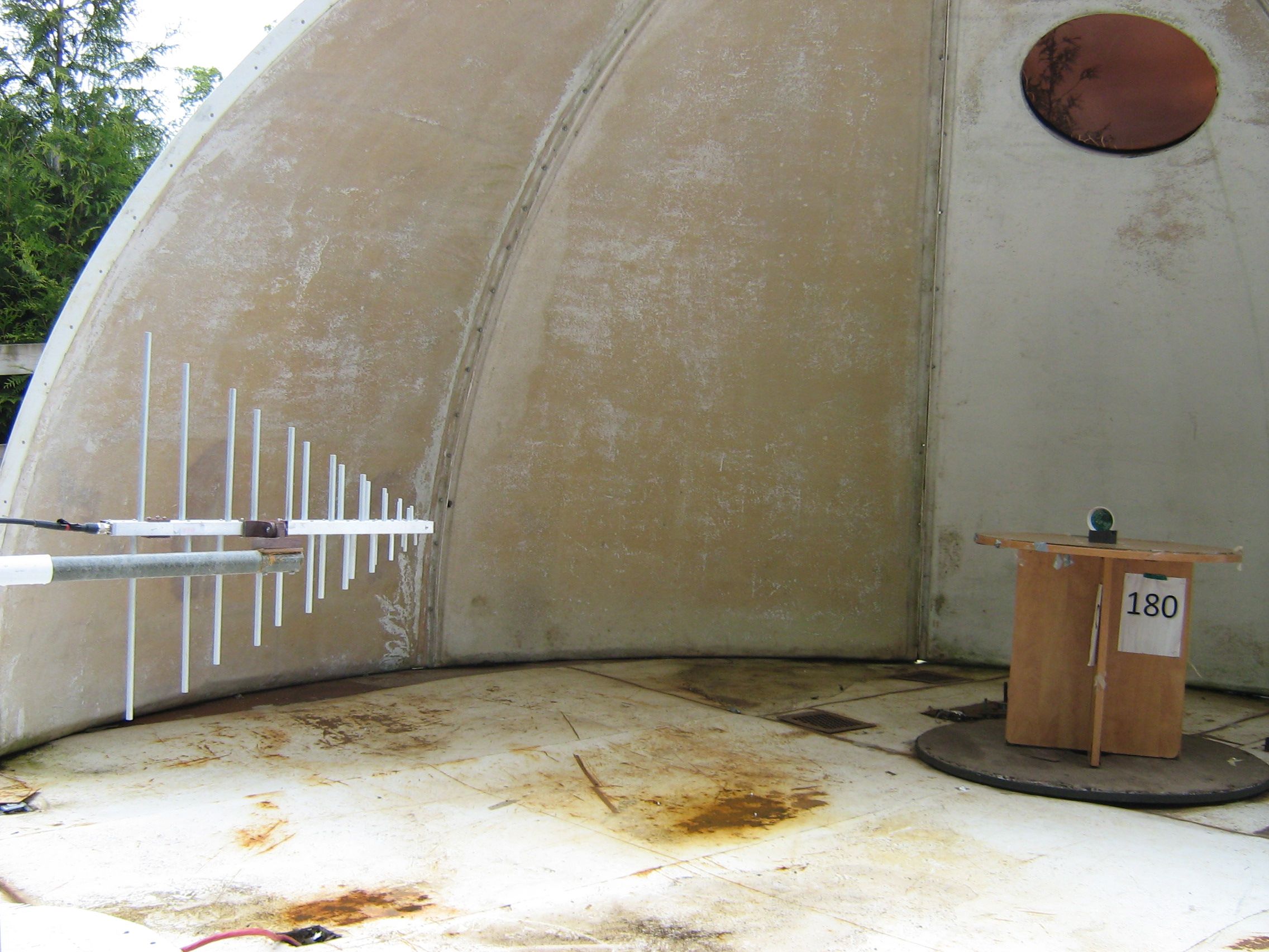
Document Text
Text extracted from the exhibit documents filed with the FCC. Open a document above to read the original.
Users Manual
USER MANUAL V1.02 EnOcean GmbH Kolpingring 18a 82041 Oberhaching Germany Phone +49.89.67 34 689-0 Fax +49.89.67 34 689-50 [email protected] www.enocean.com Subject to modifications STM110C User Manual V1.02 December 15, 2008 3:19 PM Page 1/43 Patent protected: WO98/36395 DE 100 25 561 DE 101 50 128 WO 2004/051591 DE 103 01 678 A1 RF Sensor Transmitter Module STM11xC December 15, 2008 USER MANUAL V1.02 EnOcean GmbH Kolpingring 18a 82041 Oberhaching Germany Phone +49.89.67 34 689-0 Fax +49.89.67 34 689-50 [email protected] www.enocean.com Subject to modifications STM110C User Manual V1.02 December 15, 2008 3:19 PM Page 2/43 STM11XC REVISION HISTORY The following major modifications and improvements have been made to the first version of this document: No Major Changes 0.97 Section 3.8 added “Main differences between STM110 and STM110C” 1.0 Product variant STM112C added 1.01 IC number corrected in section 4.2 Published by EnOcean GmbH, Kolpingring 18a, 82041 Oberhaching, Germany www.enocean.com, [email protected], phone ++49 (89) 6734 6890 © EnOcean GmbH All Rights Reserved Important! This information describes the type of component and shall not be considered as assured characteristics. No responsibility is assumed for possible omissions or inaccuracies. Circuitry and specifications are subject to change without notice. For the latest product specifica- tions, refer to the EnOcean website: http://www.enocean.com. As far as patents or other rights of third parties are concerned, liability is only assumed for modules, not for the described applications, processes and circuits. EnOcean does not assume responsibility for use of modules described and limits its liability to the replacement of modules determined to be defective due to workmanship. Devices or systems containing RF components must meet the essential requirements of the local legal authorities. The modules must not be used in any relation with equipment that supports, directly or indirectly, human health or life or with applications that can result in danger for people, animals or real value. Components of the modules are considered and should be disposed of as hazardous waste. Local government regulations are to be observed. Packing: Please use the recycling operators known to you. By agreement we will take pack- ing material back if it is sorted. You must bear the costs of transport. For packing material that is returned to us unsorted or that we are not obliged to accept, we shall have to in- voice you for any costs incurred. USER MANUAL V1.02 EnOcean GmbH Kolpingring 18a 82041 Oberhaching Germany Phone +49.89.67 34 689-0 Fax +49.89.67 34 689-50 [email protected] www.enocean.com Subject to modifications STM110C User Manual V1.02 December 15, 2008 3:19 PM Page 3/43 STM11XC TABLE OF CONTENT 1 GENERAL DESCRIPTION...................................................................................... 5 1.1 Basic Functionality......................................................................................... 5 1.2 Typical Applications ....................................................................................... 5 1.3 Technical Data .............................................................................................. 6 1.4 Physical Dimensions ...................................................................................... 7 1.5 Environmental Conditions ............................................................................... 7 1.6 Ordering Information ..................................................................................... 7 2 FUNCTIONAL DESCRIPTION................................................................................. 8 2.1 Block Diagram .............................................................................................. 8 Module power supply ........................................................................................... 8 Power control ..................................................................................................... 9 Power supply outputs .......................................................................................... 9 Wake-up timer.................................................................................................... 9 Processor ..........................................................................................................10 RF transmitter ...................................................................................................10 2.2 Pin Description and operational characteristics..................................................11 2.3 Absolute maximum ratings ............................................................................13 2.4 Equivalent schematics of Inputs and Outputs ...................................................14 Equivalent schematic of WAKE and /WAKE inputs ...................................................14 Equivalent schematic of wake-up cycle time inputs CW_0 to CW_1............................14 Equivalent schematic of LED output ......................................................................15 Equivalent schematic of V_SC1 input ....................................................................15 Equivalent schematic of V_SC2 input ....................................................................16 Equivalent schematic of analog inputs AD_0 to AD_2 ..............................................16 Equivalent schematic of voltage outputs V_0UT and V_REF ......................................16 2.5 Encoding Scheme of CW and CP Input Pins ......................................................17 Wake-up cycle time ............................................................................................17 Redundant retransmission ...................................................................................17 2.6 Solar Energy Balance Calculation ....................................................................18 2.7 Radio Telegram of STM11xC ..…
Text truncated - open the document above for the full version.
Cover Letter(s)
energy conservation – home and office www.echoflexsolutions.com #1 – 38924 Queens Way, Squamish, BC, Canada, V8B 0K8 Tel 604-815-0091 / Fax 604-815-0078 FEDERAL COMMUNICATIONS COMMISSION 7435 Oakland Mills Road Columbia, MD 21046 USA To Whom It May Concern: Pursuant to paragraphs 0.457(d) and 0.459 of the Commission’s rules (47 C.F.R.) and section 552(b)(4) of the Freedom of Information Act, Echoflex Solutions Inc. requests confidentiality for the following product(s): Applicant: Echoflex Solutions Inc. Product: EnOcean STM112C radio transmitter Model: STM112C FCC ID: XMG-STM112C For the product stated above, we request that the following information be held confidential. 1. Circuit schematics submitted as Equipment Authorization electronic Filing attachment: "STM112C Schematic.pdf”. 2. BOM submitted as Equipment Authorization electronic Filing attachment: “STM112C BOM.pdf”. 3. Block diagram submitted as Equipment Authorization Electronic Filing attachment: “STM112C Block Diagram.pdf”. 4. OEM Operational Legal Agreement, an operational description exhibit. The above exhibits contain Echoflex Solutions Inc.’s and EnOcean, GmbH’s trade secrets and proprietary information that could be of benefit to our competitors regarding the design of our product. This material is not customarily available to the general public and we request that it be withheld from public inspection. If you have any questions, please feel free to contact me at the address shown below. Sincerely, Kin Leong Production Manager
Cover Letter(s)
energy conservation – home and office www.echoflexsolutions.com #1 – 38924 Queens Way, Squamish, BC, Canada, V8B 0K8 Tel 604-815-0091 / Fax 604-815-0078 Timco Engineering, Inc. 849 NW State Road 45 P.O. Box 370 Newberry, FL 32669 USA Re.: Cover Letter for FCC limited modular approval submission of STM112C Job: 1429UC10 FCC: XMG-STM112C To Whom It May Concern: Echoflex Solutions Inc. wishes to apply for FCC Part 15.231 limited modular approval of the EnOcean STM112C transmitter module. Echoflex Solution is a recognized distributor of EnOcean GmbH products for North America. Echoflex Solutions also designs and manufactures products that employ various EnOcean radio modules. The STM112C transmitter is a 315MHz low-power radio transmitter used in various sensors (photocell, temperature, humidity, motion detection, etc.) for remote control of electrical appliances (light fixtures, HVAC systems, electrical machines, etc.). This STM112C is manufactured by EnOcean GmbH and is based on the same circuitry design as their STM110C which is recognized under FCC ID SZV-STM110C. The STM112C submitted here differs only in the antenna length (24cm on the STM112C versus 15cm on the STM110C). The STM112C consists only of a printed circuit board assembly with a monopole whip antenna. The module does not function on its own and is normally used as an integral part of a product. The module is typically inserted or soldered into a main board. Echoflex Solutions seeks FCC limited modular approval of this EnOcean STM112C under Part 15.231. Sincerely, Kin Leong Production Manager
Cover Letter(s)
energy conservation – home and office www.echoflexsolutions.com #1 – 38924 Queens Way, Squamish, BC, Canada, V8B 0K8 Tel 604-815-0091 / Fax 604-815-0078 FEDERAL COMMUNICATIONS COMMISSION 7435 Oakland Mills Road Columbia, MD 21046 USA To Whom It May Concern: For the product stated below: Applicant: Echoflex Solutions Inc. Product: EnOcean STM112C radio transmitter Model: STM112C FCC ID: XMG-STM112C and pursuant to Public Notice DA 00-1407 , Echoflex seeks Limited Modular Approval for the STM112C radio transmitter. 1. The modular transmitter must have its own RF shielding. This is intended to ensure that the module does not have to rely upon the shielding provided by the device into which it is installed in order for all modular transmitter emissions to comply with Part 15 limits. It is also intended to prevent coupling between the RF circuitry of the module and any wires or circuits in the device into which the module is installed. Such coupling may result in non-compliant operation. The modular transmitter has a ground plane and other grounding elements that are designed to provide adequate shielding; it was tested in an unshielded configuration and the measurements confirmed the effectiveness of the ground plane shield. The modular transmitter complies with Part 15 emissions limits. 2. The modular transmitter must have buffered modulation/data inputs (if such inputs are provided) to ensure that the module will comply with Part 15 requirements under conditions of excessive data rates or over-modulation. The modular transmitter has buffered modulation / data inputs. 3. The modular transmitter must have its own power supply regulation. This is intended to ensure that the module will comply with Part 15 requirements regardless of the design of the power supplying circuitry in the device into which the module is installed. The modular transmitter has its own power supply regulation. 4. The modular transmitter must comply with the antenna requirements of Section 15.203 and 15.204(c). The antenna must either be permanently attached or employ a "unique" antenna coupler (at all connections between the module and the antenna, including the energy conservation – home and office www.echoflexsolutions.com #1 – 38924 Queens Way, Squamish, BC, Canada, V8B 0K8 Tel 604-815-0091 / Fax 604-815-0078 cable). Any antenna used with the module must be approved with the module, either at the time of initial authorization or through a Class II permissive change. The "professional installation" provision of Section 15.203 may not be applied to modules. The modular transmitter has a permanently attached monopole whip antenna. 5. The modular transmitter must be tested in a stand-alone configuration, i.e., the module must not be inside another device during testing. This is intended to demonstrate that the module is capable of complying with Part 15 emission limits regardless of the device into which it is eventually installed. Unless the transmitter module will be battery powered, it must comply with the AC line conducted requirements found in Section 15.207. AC or DC power lines and data input/output lines connected to the module must not contain ferrites, unless they will be marketed with the module (see Section 15.27(a)). The length of these lines shall be length typical of actual use or, if that length is unknown, at least 10 centimeters to insure that there is no coupling between the case of the module and supporting equipment. Any accessories, peripherals, or support equipment connected to the module during testing shall be unmodified or commercially available (see Section 15.31(i)). The modular transmitter was tested in a solar panel powered configuration and complies with Part 15 emission limits. The modular transmitter is marketed for battery or energy harvesting (i.e. solar, thermo harvesting) power source applications, not AC line powered. 6. The modular transmitter must be labeled with its own FCC ID number, and, if the FCC ID is not visible when the module is installed inside another device, then the outside of the device into which the module is installed must also display a label referring to the enclosed module. This exterior label can use wording such as the following: "Contains Transmitter Module FCC ID: XYZMODEL1" or "Contains FCC ID: XYZMODEL1." Any similar wording that expresses the same meaning may be used. The Grantee may either provide such a label, an example of which must be included in the application for equipment authorization, or, must provide adequate instructions along with the module which explain this requirement. In the latter case, a copy of these instructions must be included in the application for equipment authorization. The modular transmitter is labeled with its own FCC ID number. Because the modular transmitter may be installed inside another device, rendering its own label invisible, the user manual instructs users of the modular transmitter that they must visibly display the necessary text (Contains FCC ID: XMG-STM112C) on the outside of the finished product. 7. The modular transmitter must comply with any specific rule or operating requirements applicable to the transmitter and the manufacturer must provide adequate instructions along with the module to explain any such requirements. A copy of these instructions must be included in the application for equipment authorization. For example, there are very strict operational and timing requirements that must be met before a transmitter is authorized for operation under Section 15.231. For instance, data transmission is energy conservation – home and office www.echoflexsolutions.com #1 – 38924 Queens Way, Squamish, BC, Canada, V8B 0K8 Tel 604-815-0091 / Fax 604-815-0078 prohibited, except for operation under Section 15.231(e), in which case there are separate field strength level and timing requirements. Compliance with these requirements must be assured. The modular transmitter complies with all applicable operating require…
Text truncated - open the document above for the full version.
Operational Description
DATA SHEET EnOcean GmbH Kolpingring 18a 82041 Oberhaching Germany Phone +49.89.67 34 689-77 Fax +49.89.67 34 689-50 [email protected] www.enocean.com Product Marketing Subject to modifications September 2008 Page 1/ 1 Features overview Power Supply solar cell or external (2.2-5.0 V) Antenna pre-inst. 9 cm (STM110) / 15 cm (STM110C) whip antenna; 50Ω output pin (STM112C) Frequency / Transmission power 868.3 MHz (STM 110) or 315.0 MHz (STM 11xC) / max. 10mW Data rate / Modulation type 125 kbps / ASK Start up time with empty energy storage <10 min @ 100 lx Operation time in total darkness >60h 1) 1) storage filled @ 1000lx, transmission every 17 min (average), 100s wake-up, temperature 25°C, Goldcap formatted Transmission range ~300m free field Input channels 4 x digital inputs, 3 x analog inputs (8 bit resolution) Ext. power supply output 3.0 V ±3%, 1mA max., ~2.6ms (during wake-up time) Ext. voltage reference output 2.05V ±3%, 1mA max., ~2.6ms (during wake-up time) Transmitting indication output (LED) 3.0V ±3%, 2mA max., 3 x 1.2 ms within 40ms Dimensions of discrete solar cell 13 x 35 mm Dimensions of PCB 21 x 40 x 9 mm (incl. energy store and wiring pins) Operating temperature - 25 up to + 65 °C Sensor Transmitter Module STM 110 and STM 11xC The extremely power saving RF transmitter module STM 110 of EnOcean enables the realization of wireless and maintenance free sensors. Power supply is provided by a small solar cell. An integrated energy store allows unrestricted functionality for several days in total darkness. Three 8 bit A/D converter inputs and 4 digital inputs facilitate multifunctional detector systems, based on application specific passive sensing components. This allows easy and comfortable monitoring of position, temperature, illumination, pressure, etc. - or simply supervising voltages or currents. The module provides a user configurable cyclic wake up (every 1, 10 or 100 sec.). After wake up a radio telegram (input data, unique 32 bit sen- sor ID, checksum) will be transmitted in case of a change of any digital input value compared to the last sending or in case of a significant change of measured analogue values (different input sensi- tivities can be selected). In case of no relevant input change a redundant retransmission signal is sent after a user configurable number of wake- ups to announce all current values. In addition a wake up via switch over of two wake pins is pro- vided. The STM 110 module serves the 868 MHz air interface protocol of EnOcean. Together with the receiver modules RCM120 and RCM 130 this module can be easily implemented into operation and control units for realization of various appli- cation specific system solutions. A 315 MHz variant – STM 11x C – is also avail- able. STM 110 is CE certified and conforms to the R&TTE EU-Directive on radio equipment. STM 11xC is conform to FCC part 15.231 and RSS-210 for use in USA and in Canada. Type STM110 STM110C STM112C Ordering Code S3001-D110 S3031-D110 S3031-D112
Test Report
EMC Compliance Test Report Rev 1.0 Echoflex Solutions STM 112C - 15.231 Echoflex So/ utions I nc. sTM 112C EMC Directive Gompliance Test Report per FCC Part 15,231 & IC RSS-210 FCC lD: XMGSTMIl2C lC lD: 7256A-STM112C Revision '1.0 June 3, 2010 Protocol Data Systems lnc, EMC Lab, Abbotsford BC, Canada. SCC ISO/17025 (CAN-PaE) Accredited Laboratory No. 612 FCC O.A.T.S. Registration Number 96437 Industry Canada O.A.T.S. Registration Number IC3384 This repoft is for the exclusive use of Protocol Data Systems Customer and is provided pursuant to the agreenent between Protocol and its Customer. Protocol's responsibi|ityandliabilityare|imitedtotheternsandconditionsoftheagreenent'ProtocoIassumesnoliabi|itytoanypafy,otherthantotheCustome|inaccordancewh the agrcement, for any loss, expense or damage occasioned by the use of this repoft. Only the Custoner is authorized to copy or distribute this report and then only in its entirety. Any use of the Protocol Data Systems nane for the sale or adveftisenent of the tested material, product or seruice nust first be approved in writing by Protocol Data Sysfems. The obsewations and lest resu/ts ln fh is report are relevant only to the sample/s fesfed. Approval Checked Byr Juno 3,2010 DAtF. Reoort Number: 03486 Page 1 of 14 EMC Compliance Test Report Rev 1.0 Echoflex Solutions STM 112C - 15.231 Report Number: 03486 Page 2 of 14 Index Section I: Report of Measurements Testing Information.................................................................... 3 Section II: Report of Measurements Test Procedure.......................................................................... 5 Section III: Report of Measurements to Radiation Interference............................................................ 6 Section IV: Report of Maximum Permissible Exposure......................................................................... 7 Section V: Report of Measurements to Periodic Operation................................................................. 8 Section VIII: Report of Measurements to Power Line Conducted Interference.................................... 12 EMC Compliance Test Report Rev 1.0 Echoflex Solutions STM 112C - 15.231 Report Number: 03486 Page 3 of 14 Section I: Report of Measurements Testing Information General Information Applicant Company Name Echoflex Solutions Inc. Address #1-38924 Queens Way Squamish,BC V5T 1G7 Phone: 604-815-0091 Ext 669 Fax 604-815-0078 Contact Person: Kin Leong Email: [email protected] Product Name STM 112C – with wire Antenna Applicable Standard FCC Part 15.231, ANSI C63.4:2003; Part 15.207, 15.209 Test Results Pass Statement of Compliance This equipment has been tested in accordance with the standards indentified in the referenced test report. To the best of our knowledge and belief, these tests were performed using the measurement procedures described in this report and demonstrate that the equipment complies with the appropriate standards. – Signature on Front Cover Page. Equipment Under Test Specification Manufacturer Echoflex Solutions Inc. Product Description STM 112C – with wire Antenna FCC ID XMGSTM112C IC ID 7256A-STM112C Model Number STM 112C – with wire Antenna Name Environment Sensor (light, temprature, motion, etc. Operating Frequency 314.954 MHz Emission Designator 547KA1D EUT Power Source 3Vdc Solar Cell Battery Test Item Production Unit Type of Equipment Fixed Antennas Wire Antenna Antenna Connector permanently attached Test Voltage 3Vdc Solar Cell Test Environment Test Facility Protocol Data Systems Inc. 28945 McTavish Road Abbotsford, BC V4X 2E7 Phone: 604-607-0012 Fax: 604-607-0019 Email: [email protected] Website: www.protocol-emc.com Test Facility ID’s SCC ISO/17025 (CAN-P-4E) Accredited Laboratory No. 612 FCC O.A.T.S. Registration Number 96437 Industry Canada O.A.T.S. Registration Number IC3384 Date Tested May 26 TH , 2010 to May 30 TH ,2010 Tested By Amandeep Singh EMC Compliance Test Report Rev 1.0 Echoflex Solutions STM 112C - 15.231 Report Number: 03486 Page 4 of 14 Test Setup Test Supporting Equipment None required Test Conditions Temperature and Humidity: 15°C, 54% Test Exercise e.g. software description, test signal, etc. The EUT was set for continuous transmit mode of operation. It only has 1 frequency. The options were for a CW and modulated frequency. Deviation from Standard/s No deviation from Standard Modification to the EUT No modifications was made. Test Equipment List Manufacturer Model Equipment Description Serial No. Next Cal HP 85650A CDN Quasi-Peak Adapter 2811A01080 12/08/10 HP 85662A Spectrum Analyzer Display 2152A03569 11/08/10 HP 8566B Spectrum Analyzer RF Section 2241A02102 11/08/10 HP 85685A RF-Preselector 3107A01222 11/08/10 EMCO 3146 Ant Log Periodic 200- 1000MHZ 9611-4699 08/08/10 EMCO 3110B Ant Biconical 20-300MHz 9401-1850 08/08/10 EMCO 3115 Horn Antenna 1-18GHz 9403-4251 20/08/10 EMCO 3825/2 LISN 2470 20/07/10 Rhientech Custom Antenna Mast N/A N/A Protocol EMC Custom Turntable N/A N/A Measurement Uncertainty Parameter Uncertainty Radio Frequency ±1 x 10⁻⁵ Total RF power, conducted ±1,5 dB RF power density, conducted ±3 dB Spurious emissions, conducted ±3 dB All emissions, radiated ±3 dB Temperature ±1 C Humidity ±5 % DC and low frequency voltages ±3 % EMC Compliance Test Report Rev 1.0 Echoflex Solutions STM 112C - 15.231 Report Number: 03486 Page 5 of 14 Section II: Report of Measurements Test Procedure Radiation Interference: The measurement was made per FCC Part 15 and IC RSS-210 Issue 6 using an Agilent model 8566B spectrum analyzer, a model 85685A Preselector, a model 85650A quasi-peak adapter, and the appropriate antenna. The analyzer was calibrated in dB above a microvolt at the output of the antenna. The resolution bandwidth was 100kHz with an appropriate sweep speed and the video bandwidth was 300kHz up to 1GHz and 1MHz with a VBW greater than or equal to the RBW above 1GHz. When an emission was found, the table was rotated to produce the maximum, si…
Text truncated - open the document above for the full version.
Contact Information
Applicant
Kin Leong(Production Manager)
Test Firm
Protocol LabsRobert Stirling
Technical Specifications
| # | Rule Parts | Frequency Range | Power Output |
|---|---|---|---|
| 1 | 15.231 | 315 MHz - 315 MHz | - |