XO8-3000TX1IC 3000 Wireless Pendant
Instant Care, Inc.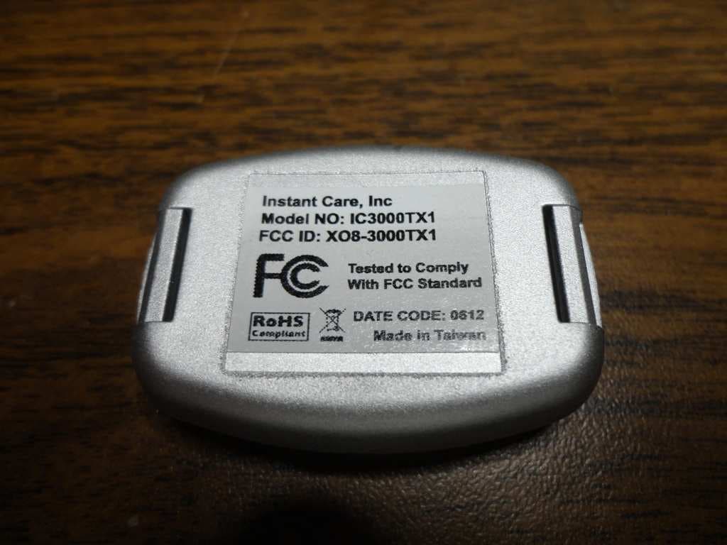
Click to zoom
Application Details
- Equipment Class
- DSC - Part 15 Security/Remote Control Transmitter
- Date of Grant
- Nov 04, 2012
- Application Purpose
- Original Equipment
- Date of Application
- Nov 04, 2012
- Equipment Note
- IC 3000 Wireless Pendant
- Frequency Range
- 433.92000000 - 433.92000000
- Company
- Instant Care, Inc.
- Country
- United States
Documents & Files
Document Text
Text extracted from the exhibit documents filed with the FCC. Open a document above to read the original.
Users Manual
Table of Contents IC 3000 MANUAL - Installation - Programming - Operation 10-24-2012 Ver. 1.9 1 Table of Contents 1. Overview ............................................................ 2 1.1 Description of Console .................................................... 2 1.2 Power and Battery Information .................................. 2 1.3 Description of Pendant ................................................... 2 1.4 LED Reporting Chart ........................................................ 4 1.5 Check-‐off List ....................................................................... 4 2. System Operations & Reporting .......................... 5 2.1 Answer/Hang-‐up Incoming Phone Calls ................. 5 2.2 AC Power Fault/Restore & Reporting ...................... 5 2.3 Console Battery .................................................................. 5 2.4 Pendant/Smoke Detector/Other Devices Low Battery ........................................................................................... 5 2.5 No Pendant Present .......................................................... 6 2.6 Automatic Check-‐in Report (Periodic Test Call) .. 6 2.7 Learning Remotes 1 & 2 ................................................. 6 2.8 Communication Formats ................................................ 6 2.9 Telephone Line Seizure ................................................... 6 2.10 Phone Line Detection .................................................... 6 2.11 Nurse Call ........................................................................... 7 2.12 Range Test .......................................................................... 7 2.13 Backup Battery Switch ................................................. 7 3. Programming Instructions ................................... 8 3.1 Local Programming .......................................................... 8 3.2 Remote Programming ..................................................... 8 3.3 Programming The IC 3000 ............................................ 9 4. Appendix .......................................................... 16 5. IC 3000 Programming Command Table .............. 18 2 1. Overview 1.1 Description of Console (P/N: IC3000V01) TOP VIEW 1. EMERGENCY button 2. NURSE button 3. CANCEL button 4. Volume Control 5. Microphone 6. POWER LED 7. STATUS LED 8. Speaker REAR VIEW 9. Line in jack (plug into tel. wall jack) 10. Phone jack (plug into user’s tel.) 11. USB Port (for programming only) BOTTOM VIEW 12. Backup battery switch Locating a suitable position for the Console. • The console should be placed on a flat surface such as a countertop or table, and located in an area that is easily accessible. • The console requires main power and a constant telephone connection. • The console should be located in the same room as the telephone jack it is connected to. • The console should not be placed in a damp location such as a bathroom. • The console should not be placed close to any heat source, such as direct sunlight, microwave oven, which can reduce signal strength. • The console should not be located alongside other radio transmitting devices such as a mobile phone, cordless phone, or wireless computer network (Wi-Fi) devices. 1.2 Power and Battery Information • Primary Voltage Input: 100-240VAC 50/60 Hz 0.2A; and Output 12VDC: 500mA. • Rechargeable battery (Ni-MH, 7.2V, 700mAh) is located inside the console, which serves as a backup in case of a power failure. • When the battery is fully charged, it serves as a backup power source for a period of at least 24hrs. It can take up to 48hrs to fully charge the battery. 24hr test performed in the toggle mode (1 way voice). • Battery switch (located at the bottom of console) is set to ON by default. If switched to OFF, the battery will be disconnected and will not be charged, nor will it serve as a backup power source when AC power is missing. 3 1.3 Description of Pendant (P/N: IC3000TX1) 1. EMERGENCY button (hold the RED button for 15 sec. to enable pendant supervisory, hold the WHITE button for 15 sec. to disable pendant supervisory) 2. NURSE button Pendant Electrical Specifications Frequency: 433.92 Mhz • Battery: CR2032, 3V 230mAh • Battery life: Typical life expectancy of 5 yrs at an average use rate of one activation per day. • Open Field Range: Approximately 600 Ft. IMPORTANT: It is recommended that the user(s) run a pendant test each week to ensure that the console is properly functioning. 4 1.4 LED Reporting Chart 1.5 Check-off List System Condition Status LED Power LED AC power fault (No AC power) Flashes Green Console power ON Solid Green Emergency call Solid Red Nurse call Solid Blue Console battery low/failure Flashes Amber Pendant low battery Solid Amber Learning mode Solid Purple Programming mode Flashes Purple Battery switch is OFF Flashes Red Account # empty / No Line1 / No pendant Flashes Red then Purple Other devices low battery Flashes Red then Amber Phone line failure Flashes Red then Blue Verified Items ☐ AC adaptor is plugged in securely ☐ Telephone line is plugged into the GREEN “Line-In port” ☐ User's telephone is plugged in the RED “telephone port” ☐ Battery switch is in the ON position ☐ Turn ON pendant check-in feature ☐ Perform test call to Monitoring Station by pressing the Red Button on the pendant ☐ Remind user to perform weekly pendant test ☐ Perform Nurse Call ☐ Ensure that the Power LED is ON and the Status LED is OFF NOTE: This equipment has been tested and found to comply with the limits for a Class B digital device, pursuant to part 15 of the FCC Rules. These limits are designed to provide reasonable protection against harmful interference in a residential installation. This equipment generates, uses and can radiate radio frequency energy and, if not installed and used in accordance with the instructions, may cause harmful interference to radio communications. However, there is no guarantee that interference will not occur in a particular i…
Text truncated - open the document above for the full version.
Users Manual
IC 3000 Wireless Pendant Part# IC3000TX1 This Pendant is designed to operate with the IC 3000 Emergency Response / Medical Triage Console. The Pendant is designed with two unique buttons. The large RED button allows a user to wirelessly trigger a telephone call for help in cases of medical emergencies, accidents, etc. that happen at home. The second smaller WHITE button with the blue medical symbol is used to place a call to a medical Triage center to ask medical questions and receive personalized professional assessment. IMPORTANT: The pendant is shipped with Emergency button disabled (shipping mode). To enable the Emergency button see Section E. A. Description of Pendant 1. Emergency Help Button • Pressing the RED button will activate the console to dial the emergency line and send an Emergency Alarm report. • Red light flashing: Signal is transmitted. 2. Nurse Call Button • Pressing the WHITE button will activate the console to dial the Nurse line • Blue light flashing: Signal is transmitted. 3. Adjustable Lanyard. B. Learning In Pendants Follow the steps below for learning in pendant Step 1. Press and hold the NURSE & CANCEL buttons on the console (approx. 5 sec.) until the console emits a beep and STATUS LED illuminates PURPLE. Now the console is in LEARNING MODE. Step 2. Learn Pendant 1: press and hold the EMERGENCY button on the console. Learn Pendant 2: press and hold the NURSE Button on the console. Step 3. The status LED will indicate either Green (Zone available) or Red (Zone Occupied). a. If the Status LED is GREEN this means that the Zone is available, press RED pendant button to learn-in. The Status LED on the console will illuminate RED and an audible beep will be heard. b. If the Status LED is RED this means that the Zone is occupied, you may clear the Zone by pressing the CANCEL button on the console until system emits a short beep and the Status LED turns green. Go to Step 3a to learn in pendant. 9-‐19-‐2012 Ver. 1.2 Step 4. To exit LEARNING MODE, press the CANCEL button. • If no signal is received within 2 minutes after entering QUICK LEARNING MODE, the console will exit and return to idle mode. • To add more than 2 pendants please reference Command 63 through 70 in the IC 3000 system manual. C. Operation • Press the RED emergency help button to activate the console to dial the emergency line and send an Emergency Alarm report. • Press the WHITE nurse call button to activate to dial the Nurse Line. D. Low Battery Detection The IC 3000 Pendant provides Low Battery Detection and Supervision features. • The IC 3000 Pendant has a battery pre-installed. The Pendants housing has been factory sealed to protect against water intrusion. • When the battery voltage becomes low, a Low Battery signal will be sent to the console. The “Status LED” on the main console will illuminate Solid YELLOW to notify the user of the condition. Additionally when a low battery condition is present a CID alert E380 will be sent. • The console will transmit a new report every 24 hours as long as the condition exists. • The low battery pendant must be replaced with new a pendant. Discard the low battery pendant. E. Enable/Disable Emergency Button (shipping mode) • To enable the Emergency button, press & hold the RED button on the pendant for 15 seconds. The pendant will flash RED to indicate the feature is enabled. • To disable the Emergency button (or put pendent into shipping mode), press & hold the WHITE button on the pendant for 15 seconds. The pendant will flash BLUE to indicate the feature is disabled. F. Electrical Specifications • Frequency: 433.92 Mhz • Battery: CR2032, 3V 230mAh • Battery life: Typical life expectancy of 5 yrs at an average use rate of one activation per day. • Open Field Range: Approximately 600 Ft. FCC Statement This device complies with Part 15 of the FCC Rules. Operation is subject to the following two conditions: (1) This device may not cause harmful interference, and (2) This device must accept any interference received, including interference that may cause undesired operation. FCC Caution Changes or modifications made to this IC 3000 Pendant that are not expressly approved by Instant Care could void the user’s authority to operate this equipment.
ID Label/Location Info
FCC Label Placement
ID Label/Location Info
Label Artwork
Test Report
EMC Report for Instant Care, Inc. on the Pendant Wireless Remote FCC Part 15.231 File: 100731916LAX-004 Page 1 of 18 TEST REPORT Report Number: 100731916LAX-004 Project Number: G100731916 July 31, 2012 Testing performed on the Pendant Wireless Remote Model Number: IC 3000TX1 FCC ID: XO8-3000TX1 to FCC Part 15.231 RSS 210 for Instant Care, Inc. Test Performed by: Test Authorized by: Intertek 25791 Commercentre Drive Lake Forest, CA 92630 USA Instant Care, Inc. 2310 Cousteau Ct. Vista, CA 92081 USA Prepared by: Date: July 31, 2012 David O’Reilly Engineering Team Leader Reviewed by: Date: July 31, 2012 Ollie Moyrong Engineering Manager This report is for the exclusive use of Intertek's Client and is provided pursuant to the agreement between Intertek and its Client. Intertek's responsibility and liability are limited to the terms and conditions of the agreement. Intertek assumes no liability to any party, other than to the Client in accordance with the agreement, for any loss, expense or damage occasioned by the use of this report. Only the Client is authorized to copy or distribute this report and then only in its entirety. Any use of the Intertek name or one of its marks for the sale or advertisement of the tested material, product or service must first be approved in writing by Intertek. The observations and test results in this report are relevant only to the sample tested. This report by itself does not imply that the material, product, or service is or has ever been under an Intertek certification program. This report must not be used to claim product endorsement by A2LA, NIST nor any other agency of the U.S. Government. EMC Report for Instant Care, Inc. on the Pendant Wireless Remote FCC Part 15.231 File: 100731916LAX-004 Page 2 of 18 TABLE OF CONTENTS 1.0 Summary of Tests ......................................................................................................................... 3 2.0 General Description ...................................................................................................................... 4 2.1 Product Description............................................................................................................ 4 2.2 Related Submittal(s) Grants ............................................................................................... 4 2.3 Test Methodology .............................................................................................................. 4 2.4 Test Facility........................................................................................................................ 4 3.0 System Test Configuration ........................................................................................................... 5 3.1 Support Equipment and Description .................................................................................. 5 3.2 Block Diagram of Test Setup ............................................................................................. 5 3.3 Justification ........................................................................................................................ 6 3.4 Software Exercise Program ................................................................................................ 6 3.5 Mode of Operation During Test ......................................................................................... 6 3.6 Modifications Required for Compliance ............................................................................ 6 3.7 Additions, Deviations and Exclusions from Standards...................................................... 6 4.0 Measurement Results.................................................................................................................... 7 4.1 Radiated Emission.............................................................................................................. 7 4.1.1 Procedure .............................................................................................................. 7 4.1.3 Test Results ........................................................................................................... 9 4.2 AC Line Conducted Emission ............................................................................................ 10 4.3 Occupied Bandwidth.......................................................................................................... 11 4.4 Transmitter Deactivation Time........................................................................................... 13 4.5 Duty Cycle Graphs ............................................................................................................. 14 5.0 List of Test Equipment ................................................................................................................. 17 6.0 Document History ......................................................................................................................... 18 EMC Report for Instant Care, Inc. on the Pendant Wireless Remote FCC Part 15.231 File: 100731916LAX-004 Page 3 of 18 1.0 Summary of Tests MODEL: IC 3000TX1 FCC ID: XO8-3000TX1 TEST FCC REFERENCE IC REFERENCE RESULTS Radiated Emission 15.231(b) RSS-210 A1.1.2 Complies Out of Band Radiated Emission 15.231(b) RSS-210 A1.1.2 Complies AC Conducted Emission 15.207 ICES-003 Not Applicable* 20 dB Bandwidth 15.231(c) RSS-210 A1.1.3 Complies Transmitter Deactivation Time 15.231(a) RSS-210 A1.1.1(a) Complies Frequency Tolerance 15.231(d) - Not Applicable Antenna Requirement 15.203 - Complies** *EUT is Battery Powered. ** EUT has internal antenna permanently attached. Tests performed by: Date: July 31, 2012 David O’Reilly Engineering Team Leader Reviewed by: Date: July 31, 2012 Ollie Moyrong Engineering Manager EMC Report for Instant Care, Inc. on the Pendant Wireless Remote FCC Part 15.231 File: 100731916LAX-004 Page 4 of 18 2.0 General Description 2.1 Product Description Overview of the EUT Applicant Instant Care,…
Text truncated - open the document above for the full version.
Test Setup Photos
During assessment, the transmitter laying flat on t he table was found to be the position where the gre atest RF levels were measured, and is pictured in the photos on the following page s. See the report for full details.
Contact Information
Applicant
Richard Darling(CEO)
Technical Contact
Instant CareGeorge Seelman
[email protected]951-816-9228
2310 Cousteau Ct. · Vista, California · United States
Non-Technical Contact
Instant CareRich Darling
[email protected]760-598-2273
Test Firm
Intertek Testing Services NA, Inc.Charles Parker
Technical Specifications
| # | Rule Parts | Frequency Range | Power Output |
|---|---|---|---|
| 1 | 15.231 | 433.92 MHz - 433.92 MHz | - |
Other Applications from Instant Care, Inc.

XO8-FS319V2
Jul 15, 2026Fall Sensor
Equipment Class
DSC - Part 15 Security/Remote Control Transmitter
XO8-HALO319V2
Jul 14, 2026Halo Transmitter
Equipment Class
DSC - Part 15 Security/Remote Control Transmitter
XO8-FS917V2
Dec 04, 2025Fall Sensor
Equipment Class
DXX - Part 15 Low Power Communication Device Transmitter
XO8-HALO917V2
Dec 04, 2025Halo Transmitter
Equipment Class
DXX - Part 15 Low Power Communication Device Transmitter
XO8-FS900Z
Sep 29, 2024Fall Sensor
Equipment Class
DXX - Part 15 Low Power Communication Device Transmitter