XOH-ZLINK2AMobile Patient Management System
Medtronic Monitoring, Inc.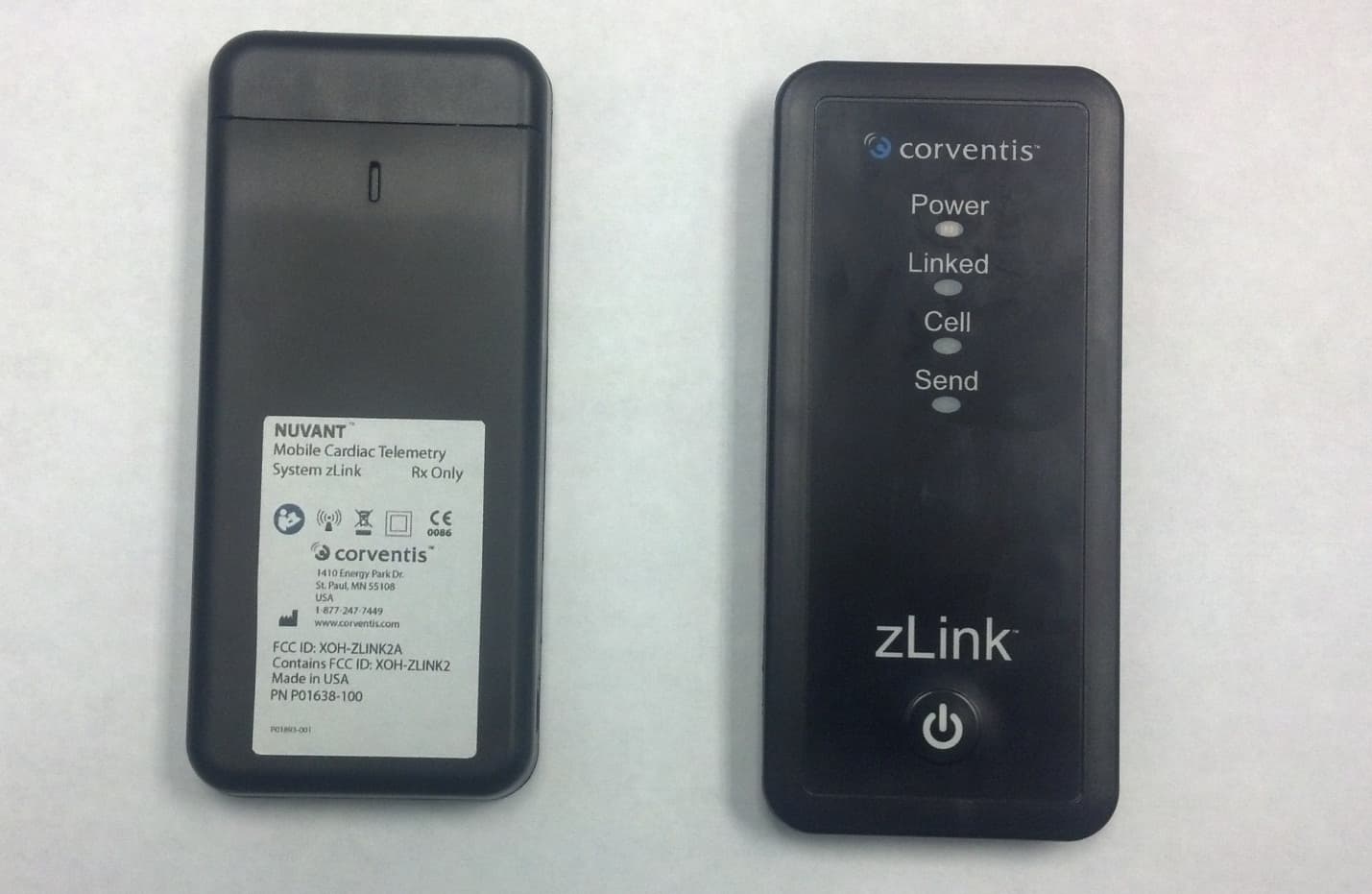
Click to zoom
Application Details
- Equipment Class
- DSS - Part 15 Spread Spectrum Transmitter
- Date of Grant
- May 15, 2014
- Application Purpose
- Original Equipment
- Date of Application
- May 15, 2014
- Equipment Note
- Mobile Patient Management System
- Frequency Range
- 2402.00000000 - 2480.00000000
- Company
- Medtronic Monitoring, Inc.
- Country
- United States
Documents & Files
Document Text
Text extracted from the exhibit documents filed with the FCC. Open a document above to read the original.
Users Manual
NUVANT ™ Mobile Cardiac Telemetry (MCT) System 1 ENGLISH NUVANT ™ MCT Instructions for Use Instructions for Use Rx Only FOLLOW THESE INSTRUCTIONS CAREFULLY AND WATCH YOUR INSTRUCTIONAL VIDEO BEFORE USING NUVANT MCT Customer Service: USA: 1-877-247-PIIX(7449) The NUVANT Mobile Cardiac Telemetry (MCT) System is a wearable, wire- less arrhythmia detection system that is used to aid clinicians in diagnosing suspected cardiac arrhythmias. It consists primarily of the PiiX ® wearable monitoring device, the zLink ® portable data transmission device and a Patient Trigger Magnet to enable on-demand collection of ECGs (recordings of heart rhythm). In combination with interpretation services provided by the Corventis Monitoring Center, as well as secure online review of data (for prescribing phy- sicians only), NUVANT MCT enables patient- and physician-friendly arrhythmia detection for up to 30 days at a time. How NUVANT MCT Works Once activated, the wearable PiiX sensor continuously monitors the heart and automatically collects ECGs when rhythm abnormalities are detected. Patients can also drive collection of ECGs when they experience cardiac symptoms by using the Patient Trigger Magnet. Data are automatically transmitted from the PiiX to the zLink, which then automatically transmits the data to the Corventis Monitoring Center. Certified cardiographic technicians at the Corventis Monitoring Center review received data and document symptoms reported by patients. Clinical reports, prepared by the Corventis Monitoring Center, are delivered and made available at www.corventis.com to provide data to prescribing physicians for the diagnosis and identification of various clinical conditions, events and/or trends. Prescribing physicians may also be contacted by the Corventis Monitoring Center directly when arrhythmias that meet pre- defined criteria are detected. IMPORTANT: • The NUVANT MCT System is not intended to be an alarm or to alert patients or physicians, and will not summon emergency response in the event help is needed. • The NUVANT MCT System is not intended to replace direct com- munication with healthcare providers. • Data provided by the system should be used by physicians along with all other clinical findings and exams to come to a diagnosis. • Patients should talk to their healthcare provider immediately if there are any concerns or if their condition changes. P01281-005 (05/13) NUVANT ™ MCT Instructions for Use 2 ENGLISH Table of Contents Getting Started ..........................................................................................2 Using NUVANT MCT During the Monitoring Period ..............................6 What to do at the End of Monitoring .....................................................8 Indications for Use, Contraindications, Warnings ..................................9 Physician Services ......................................................................................10 Specifications, Compliance and Symbols ................................................11 Frequently Asked Questions ....................................................................15 Contact Information ..................................................................................16 Getting Started Step 1: Locate the components of the NUVANT MCT System PiiX is a wearable device that collects and transmits physiological data. One or more PiiX devices may be included in the package, depending on the length of the prescription power linked cell send zLink is a device that receives data from the PiiX and transmits it to Corventis Patient Trigger Magnet is used to collect a record of your heart rhythm (ie, ECG) when symptoms are felt Link Holster is a wearable holder for the zLink zLink Charger is used to charge the zLink Prep Wipes are used for cleaning skin before applying the PiiX Product Literature including these instructions, an instructional DVD, the Notice of Privacy Practices and a NUVANT MCT patient travel card NUVANT ™ MCT Instructions for Use 3 ENGLISH Step 2: Charge the zLink • Connect the zLink Charger connector to the zLink and plug it into a standard electrical outlet • If the lights on the zLink do not turn on, push the round Power button for at least 2 seconds • Allow the zLink to charge for at least 6 hours Step 3: Prepare for PiiX Application • Trim as much hair as possible from the intended location [for men] on the upper left chest, as seen in the diagram (for example, using an electric razor or hair trim- mer). Trim an area slightly larger than the PiiX • Using the Prep Wipe provided, clean the skin where the PiiX will be applied and allow time to dry (clean an area slightly larger than the PiiX) • Do not use any creams or lotions on your skin before application as this will impact monitoring IMPORTANT: Monitoring will be affected if hair is not trimmed or if skin is not cleaned with the Prep Wipe. If this happens, you may be required to use another PiiX. • Remove the PiiX from the foil pouch by tearing at the notch. If you see any lights on the PiiX before application, contact Corventis Customer Service at 1-877-247-PIIX (7449) • Grasp the top side of the PiiX as seen in the diagram and turn it over to view the underside • Carefully pull each tab from the underside of the PiiX to expose the adhesive area IMPORTANT: Take care not to touch the gel areas and not to fold the fabric on to itself while you handle the PiiX. 4 NUVANT ™ MCT Instructions for Use ENGLISH Step 4: Apply the PiiX to your Chest • Bring the PiiX close to your upper left chest, taking care to hold it only as described in Step 3 • As seen in the diagrams below, position the end of the PiiX with “Corventis” just below the collarbone and angle the device towards the nipple. To minimize skin irritation, do not place the PiiX over broken or damaged skin Sternum Collarbone MALE Sternum Collarbone MALE Sternum Collarbone FEMALE • Petite patients can angle the PiiX slightly away from the nipple and towards…
Text truncated - open the document above for the full version.
RF Exposure Info
This report is for the exclusive use of Intertek's Client and is provided pursuant to the agreement between Intertek and its Client. Intertek's responsibility and liability are limited to the terms and conditions of the agreement. Intertek assumes no liability to any party, other than to the Client in accordance with the agreement, for any loss, expense or damage occasioned by the use of this report. Only the Client is authorized to permit copying or distribution of this report and then only in its entirety. Any use of the Intertek name or one of its marks for the sale or advertisement of the tested material, product or service must first be approved in writing by Intertek. The observations and test results in this report are relevant only to the sample tested. This report by itself does not imply that the material, product, or service is or has ever been under an Intertek certification program. 731 Enterprise Drive Lexington, KY 40510 Telephone: 859-226-1000 Facsimile: 859-226-1040 www.intertek-etlsemko.com TEST REPORT Report Number: 101275145LEX-001 Project Number: G101275145 Evaluation of Model Number: zLink FCCID: XOH-ZLINK2 Tested to the SAR Criteria in FCC Part 2.1093 For Corventis Test Performed by: Test Authorized by: Intertek 731 Enterprise Drive Lexington, KY 40510 Corventis 1410 Energy Park Drive, Suite 1 St. Paul, MN 55108 Prepared By:_______________________________Date:_______________ Bryan Taylor, Team Leader Approved By:______________________________Date:________________ Jason Centers, Senior Project Engineer 4/16/2014 4/16/2014 731 Enterprise Drive, Lexington KY 40510 Evaluation For:Corventis Model Number: zLink Report Number: 101275145LEX-001 Page 2 of 68 TABLE OF CONTENTS 1.0 DOCUMENT HISTORY ................................................................................................................ 3 2.0 INTRODUCTION ............................................................................................................................ 4 M ODIFICATIONS MADE TO TEST SAMPLE .................................................................................................. 4 3.0 TEST SITE DESCRIPTION ........................................................................................................... 5 MEASUREMENT EQUIPMENT ..................................................................................................................... 6 MEASUREMENT UNCERTAINTY ................................................................................................................ 7 4.0 JOB DESCRIPTION ....................................................................................................................... 9 5.0 SYSTEM VERIFICATION .......................................................................................................... 13 S YSTEM VALIDATION.............................................................................................................................. 13 TISSUE SIMULATING LIQUID DESCRIPTION AND VALIDATION ............................................................... 14 6.0 EVALUATION PROCEDURES .................................................................................................. 16 TEST POSITIONS: ..................................................................................................................................... 16 REFERENCE POWER MEASUREMENT: ..................................................................................................... 16 AREA SCAN: ............................................................................................................................................ 16 Z OOM SCAN: ........................................................................................................................................... 16 I NTERPOLATION, EXTRAPOLATION AND DETECTION OF MAXIMA: ........................................................ 18 P OWER DRIFT MEASUREMENT: .............................................................................................................. 19 RF AMBIENT ACTIVITY:.......................................................................................................................... 19 7.0 CRITERIA ...................................................................................................................................... 20 8.0 TEST CONFIGURATION ............................................................................................................ 20 9.0 TEST RESULTS ............................................................................................................................ 22 C ONDUCTED OUTPUT POWER MEASUREMENTS: .................................................................................... 22 SIMULTANEOUS TRANSMISSION CALCULATIONS (BLUETOOTH AND CELLULAR RADIO): ..................... 25 SAR TEST EXCLUSIONS: ......................................................................................................................... 25 10.0 REFERENCES ........................................................................................................................... 27 11.0 APPENDIX – SAR PLOTS ....................................................................................................... 28 12.0 APPENDIX – DIPOLE VALIDATION PLOTS ..................................................................... 60 731 Enterprise Drive, Lexington KY 40510 Evaluation For:Corventis Model Number: zLink Report Number: 101275145LEX-001 Page 3 of 68 1.0 DOCUMENT HISTORY Revision/ Project Number Writer Initials Date Change 1.0 /G101275145 BT 4/14/2014 Original document 731 Enterprise Drive, Lexington KY 40510 Evaluation For:Corventis Model Number: zLink Report Number: 101275145LEX-001 Page 4 of 68 2.0 INTRODUCTION At the request of Corventis, the zLink Gatewy was evaluated for SAR in accordance with the requirements for FCC Part 2.1093 and RSS-102. Testing was performed in accordance with IEEE Std 1528…
Text truncated - open the document above for the full version.
Test Report
Non-Specific EMC Report Shell Rev. July 2013 Page 1 of 92 Client: Corventis, Model: zLink EMISSIONS TEST REPORT Report Number: 101275145BOX-009 Project Number: G101275145 Report Issue Date: 03/30/2014 Product Designation: zLink (Bluetooth) Standards: FCC Part 15:2014 Subpart C Section 15.247, FCC Part 15:2014 Subpart B Class B, RSS-210 Issue 8 December 2010, ICES-003 Issue 5 August 2012 RSS-Gen Issue 3 December 2010 Tested by: Client: Intertek Testing Services NA, Inc. 70 Codman Hill Road Boxborough, MA 01719 USA Corventis 1410 Energy Park Drive Suite #1 St. Paul, MN 55108 USA Report prepared by Reviewer Report reviewed by Vathana Ven / Sr. Project Engineer, EMC Kouma Sinn / Sr. Project Engineer, EMC Intertek Report Number: 101275145BOX-009 Issued: 03/30/2014 Non-Specific EMC Report Shell Rev. July 2013 Page 2 of 92 Client: Corventis, Model: zLink 1 Introduction and Conclusion The tests indicated in section 2.0 were performed on the product constructed as described in section 4.0. The remaining test sections are the verbatim text from the actual data sheets used during the investigation. These test sections include the test name, the specified test Method, a list of the actual Test Equipment Used, documentation Photos, Results and raw Data. No additions, deviations, or exclusions have been made from the standard(s) unless specifically noted. Based on the results of our investigation, we have concluded the product tested complies with the requirements of the standard(s) indicated. The results obtained in this test report pertain only to the item(s) tested. 2 Test Summary Section Test full name Result 3 Client Information -- 4 Description of Equipment Under Test -- 5 System Setup and Method -- 6 Maximum Peak Output Power, Human RF Exposure and Duty Cycle FCC 15:2011 Subpart C, Section 15.247 (b) (1), (4) RSS-210 Issue 8 December 2010, A8.4 (2), IC RSS-102 Issue 4 March 2010, CFR47 Part 2.1093 Pass 7 Transmitter Radiated Spurious Emissions FCC 15:2013 Subpart C Section 15.247 (d) RSS-210 Issue 8 December 2010, A8.5 Pass 8 Hopping Channel Separation FCC 15:2013 Subpart C Section 15.247 (a)(1) RSS-210 Issue 8 December 2010, A8.1 (b) Pass 9 Number of Hopping Frequency FCC 15:2013 Subpart C Section 15.247 (a)(1) (iii) RSS-210 Issue 8 December 2010, A8.1 (d) Pass 10 Hopping Channel Bandwidth FCC 15:2013 Subpart C Section 15.247 (a)(1) RSS-210 Issue 8 December 2010, A8.1 (b) Pass 11 Hopping Dwell time FCC 15:2011 Subpart C Section 15.247 (a)(1) (iii) RSS-210 Issue 8 December 2010, A8.1 (d) Pass 12 Band-edge Compliance FCC 15:2013 Subpart C Section 15.247 (d) RSS-210 Issue 8 December 2010, A8.5 Pass 13 Receiver Radiated Spurious FCC Part 15:2013 Subpart B Section 15.109 (a) RSS-Gen Issue 3 December 2010, Section 6.1 (Table 2) Pass 14 AC Line Conducted Emissions (CFR47 FCC Part 15 Subpart B 15.207, IC RSS-Gen Section 7.2.4) Pass 15 Revision History -- Intertek Report Number: 101275145BOX-009 Issued: 03/30/2014 Non-Specific EMC Report Shell Rev. July 2013 Page 3 of 92 Client: Corventis, Model: zLink 3 Client Information This EUT was tested at the request of: Client: Corventis 1410 Energy Park Drive Suite #1 St. Paul, MN 55108 USA Contact: Mr. Brett Landrum Telephone: 651-925-3778 Fax: None Email: [email protected] 4 Description of Equipment Under Test Manufacturer: Corventis 1410 Energy Park Drive Suite #1 St. Paul, MN 55108 USA Equipment Under Test Description Manufacturer Model Number Serial Number Wireless Transmitter (Bluetooth) Corventis zLink 015821 Receive Date: 02/24/2014 Test Date:03/12/2014 – 03/24/2014 Received Condition: Good Type: Production FCC IC ID:Not available Description of Equipment Under Test (provided by client) Bluetooth utilizes 79 channels starting at 2402 MHz and extending to 2480 MHz. Channels 0 (2402 MHz), 38 (2440 MHz) and 79 (2480 MHz) were selected for testing. The device has an integral antenna. Equipment Under Test Power Configuration Rated Voltage Rated Current Rated Frequency Number of Phases 100-240VAC 1.1 50/60Hz N/A 3.7VDC 1.8Ah N/A N/A Operating modes of the EUT: No. Descriptions of EUT Exercising 1 Transmit mode – hopping enabled (DH1, DH3, and DH5) or hopping disabled, modulated on a single channel 2 Receive mode Software used by the EUT: No. Descriptions of EUT Exercising 1 Pre-programmed using Tera Term 4.61 Intertek Report Number: 101275145BOX-009 Issued: 03/30/2014 Non-Specific EMC Report Shell Rev. July 2013 Page 4 of 92 Client: Corventis, Model: zLink 5 System Setup and Method Cables ID Description Length (m) Shielding Ferrites Termination None Support Equipment Description Manufacturer Model Number Serial Number Laptop Dell Latitude D630 JX7XX61 43367588497 5.1 Method: Configuration as required by ANSI C 63.10:2013, FCC Part 15:2013 Subpart C Section 15.247, RSS-210 Issue 8 December 2010, RSS-Gen Issue 3 December 2010, IC RSS-102 Issue 4 March 2010, CFR47 Part 2.1093. 5.2 EUT Block Diagram: Intertek Report Number: 101275145BOX-009 Issued: 03/30/2014 Non-Specific EMC Report Shell Rev. July 2013 Page 5 of 92 Client: Corventis, Model: zLink 6 Maximum Peak Output Power, Human RF Exposure and Duty Cycle 6.1 Method Tests are performed in accordance with FCC Part 15 Subpart C Section 15.247, CFR47 Part 2.1093, ANSI C63.10, RSS-Gen, RSS-210 Annex 8, and IC RSS-102 Issue 4. TEST SITE: 10m ALSE The 10m ALSE is 13m (Length) x 21m (Depth) x 10m (Height) with the effective size in terms of space from the tips of the absorber is 12m (Length) x 20m (Depth) x 8.5m (Height). This chamber achieves broadband performance using a unique arrangement of hybrid and ferrite tile absorber. This chamber has a built in 3m diameter turntable (Embedded type). The metal structure of the table makes electrical connection around the entire circumference of the turntable to the ground plane with a metal brush type connection. The turntable is located on one end of the chamber and the antennas are mounted 3 and 10 meters away at the other end of the chamber on the adjustable a…
Text truncated - open the document above for the full version.
Test Setup Photos
Intertek Report Number: 101275145BOX-009 Issued: 03/30/2014 Non-Specific EMC Report Shell Rev. July 2013 Page 8 of 92 Client: Corventis, Model: zLink 6.4 Setup Photographs: EUT on its back Intertek Report Number: 101275145BOX-009 Issued: 03/30/2014 Non-Specific EMC Report Shell Rev. July 2013 Page 9 of 92 Client: Corventis, Model: zLink EUT on its long side Intertek Report Number: 101275145BOX-009 Issued: 03/30/2014 Non-Specific EMC Report Shell Rev. July 2013 Page 10 of 92 Client: Corventis, Model: zLink EUT on its short side
Contact Information
Applicant
Charles S Farlow(Program Director, Regulatory Affairs)
Technical Contact
CorventisBrett Alan Landrum
[email protected]651.925.3778
1410 Energy Park Drive · St. Paul · United States
Non-Technical Contact
CorventisBrett Alan Landrum
[email protected]651.925.3778
Test Firm
Intertek Testing Services NA Inc.Yaqing Liu
[email protected]978 635 8662
Technical Specifications
| # | Rule Parts | Frequency Range | Power Output |
|---|---|---|---|
| 1 | 15C | 2.40 GHz - 2.48 GHz | 1.00 mW |
Other Applications from Medtronic Monitoring, Inc.
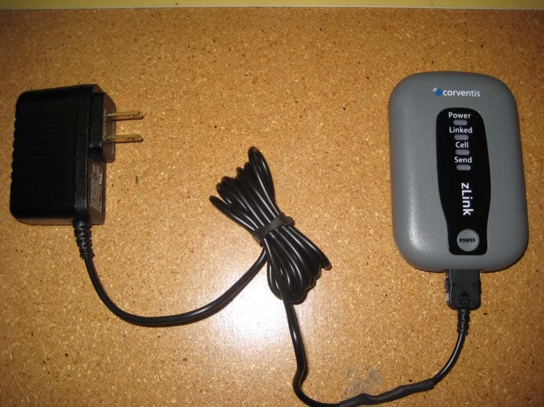
XOH-ZLINK001
Nov 29, 2010Cardiac Telemetry Device
Equipment Class
DSS - Part 15 Spread Spectrum Transmitter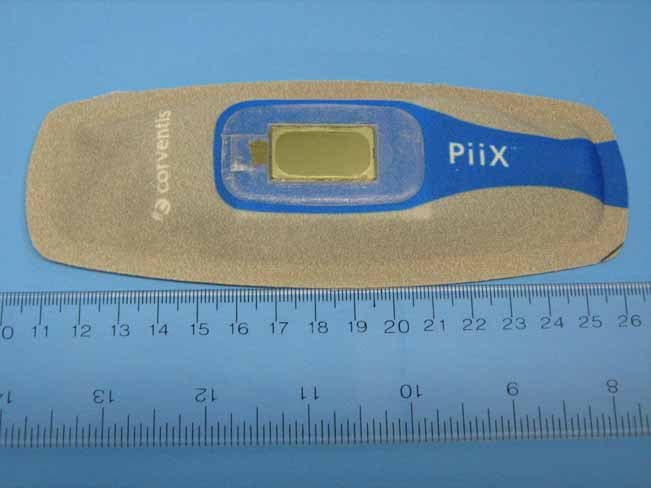
XOH-PIIX
Feb 17, 2010Mobile Patient Management System
Equipment Class
DTS - Digital Transmission System