XOYPOSITRONGSM/GPRS POS Terminal
Golden Port Technology Limited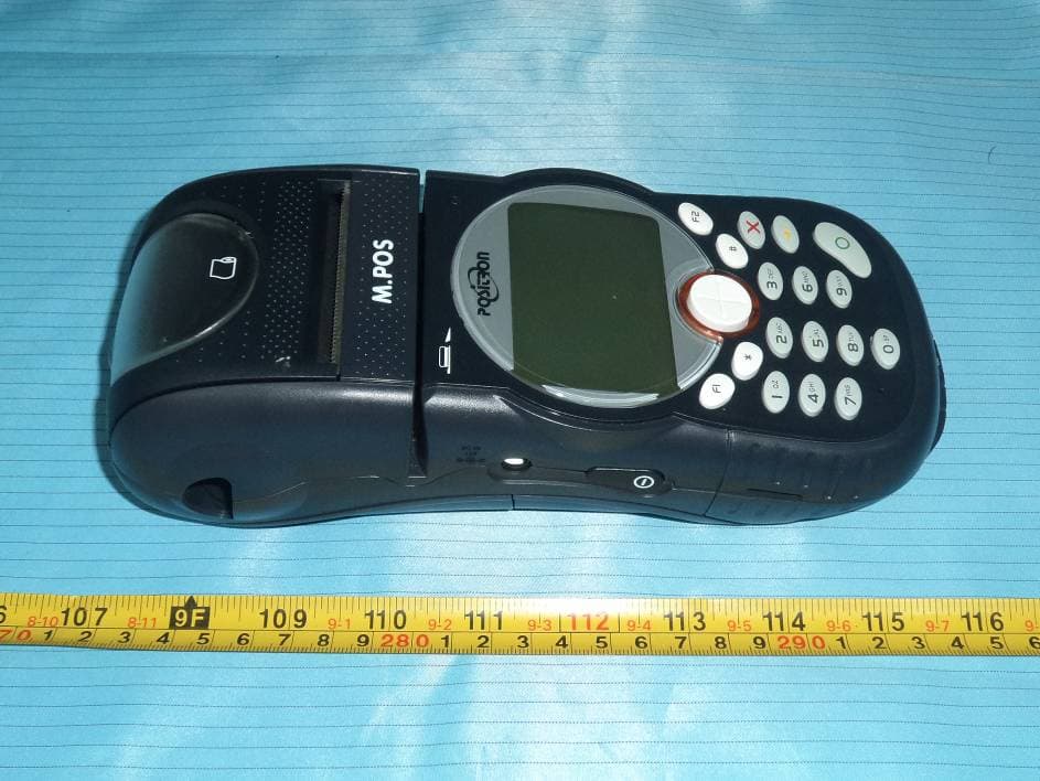
Click to zoom
Application Details
- Equipment Class
- PCB - PCS Licensed Transmitter
- Date of Grant
- Apr 06, 2012
- Application Purpose
- Original Equipment
- Date of Application
- Apr 06, 2012
- Equipment Note
- GSM/GPRS POS Terminal
- Frequency Range
- 1850.20000000 - 1909.80000000
- Country
- China
Documents & Files
Document Text
Text extracted from the exhibit documents filed with the FCC. Open a document above to read the original.
Users Manual
User Guide www.mpos.net Contents 1. Contents of Positron Package .............................................................................1 2. Layout and Description .........................................................................................2 2.1 Overview of Positron 2.2 Terminal Front 2.3 Terminal Sides 2.4 Terminal Back 3. Procedure of Loading of Thermal Paper .........................................................7 4. Battery .........................................................................................................................8 4.1 Installation 4.2 Charging the Battery 4.3 Important Battery Information 5. Accessories ..............................................................................................................10 6. Troubleshooting ....................................................................................................12 7. Care and maintenance ........................................................................................13 8. FCC Compliance Statement...............................................................................13 Disclaimer M.POS assumes no liability for loss or damages arising directly or indirect from any misuse of Terminal and accessories or non-compliance with the instructions set out in this user guide. Specifications and external appearance are subject to change with out prior notice. 1 Contents of Positron Package 1. Contents of Positron Package P ositron is a highly secure all-in-one Point of Sale terminal equipped with both magnetic strip and Smart Card readers. It is a rugged, robust and durable handheld terminal offering optimal performance suitable for heavy duty merchants indoor and outdoor. The Positron package contains: u 1 P ositron terminal u 1 U ser Guide u 1 Li-ion Ba ttery u 1 P ower Adapter u 1 P ower Cable u 1 Thermal Paper Option al Accessories: u P rivacy Shield u Handsfr ee kit u Handset k it u D urable leather case u I n-vehicle cigarette lighter charger u RS -232 cable u USB cable u Landline t elephone cable u S eparated Charger u W all mount u Bar code scanner u Optical mar k reader u Ex ternal impact printer u C ommunication Module: l GSM/GPRS: 850 / 1900 MH z l l LAN PSTN: V.21, V.22 bis, V.22, V.32, Bell 212A 1 2 3 4 5 1 2 5 3 4 (This is only used when the firmware need be updated) 2. Layout and Description 2.1 Overview of Positron 2 Layout and Description Easy-Loading Thermal Printer Printing Paper Indicator LCD Screen Paper Cutter Backlit Keypad Magnetic Card Reader Smart Card Reader Navigation Key Function Keys Alpha-numeric Keys Indicator LED Terminal Front Transaction Approved Printing...... 3 Printing Paper Indicator Li-ion Battery Power Key Li-ion Battery Layout and Description Terminal Sides (Left) (Right) RS232 Serial Port USB Port Earphone Inlet Communication Module Communication Module Power Supply Connector 4 Layout and Description Terminal Back Li-ion Battery Communication Module SIM Card Socket SAM Card Sockets 2.2 Terminal Front Thermal Printer l A fast, quiet, easy-loading thermal printer is built in to the Positron. See section 3 for procedure for loading thermal paper. Printing Paper Indicator l inspect the remaining printer paper through the window. LCD Screen l 240 x 160 pixel large graphical LCD l White LED backlit Backlit Keypad Magnetic Card Reader l Swipe the magnetic card from left to right or from right to left, with the strip facing you. Smart Card Reader l Indicates the position to insert the Smart Card. l Insert the smart card horizontally with the chip facing upwards and leave in position during the transaction. Navigation Key l Easy-to-use 4-way navigation key. Scroll Up and Down, Left and Right. Red Key X l Cancels the procedure in progress Yellow Key y l Cancels the last character Green Key l Validates the input selections and information Function Keys l Programmable Function keys above the keypad, labeled F1, *, #, F2. Alpha-numeric Keys l High security Pin Pad 5 Layout and Description 6 Layout and Description Indicator LED l Green (slow flashing): Power on. l Green (fast flashing): Connecting to network. l Green (steady): Battery is fully charged. l Orange (fast flashing): Out of paper. l Orange (steady): Battery charging. l Red (slow flashing): Low battery level. l Red (fast flashing): Hacker attack. l Red (steady): Operating system disorder. 2.3 Terminal Side Power Key l Press Power Key to turn the terminal on or off. USB Port l Indicates the position to plug in the USB cable for connecting to different peripheral. RS232 Serial Port l Indicates the position to plug in the RS232 cable for connecting to different peripheral. Power Supply Connector l Indicates the socket position to plug in the Power Cable. Use Power Supply Cable and Adapter supplied by M.POS which specifically designed for the terminal and has complied with applicable standards. Earphone Inlet l Indicates the position to plug in the earphone. 2.4 Terminal Back Communication Module l Swap for different communication module for different communication option. Caution 7 Procedure for loading of thermal paper 3. Procedure for Loading of Thermal Paper 1. Place your thumb and index finger as shown in Figure3.1. Ensure your thumb is positioned on the “”. 2. Lift up the printer cover lever with your index finger. 3. Open the printer cover. (Remove the empty roll of thermal paper from tray, if any.) Do not touch the printer mechanism. 4. Insert a new roll of thermal paper into the empty tray. Ensure the paper end facing upward at your direction. 6. Thermal paper loading is completed Do not put your finger on the paper cutter. 5. Place the paper end on the cutter. Then, close the printer cover. Figure 3.1 Figure 3.2 Figure 3.3 Figure 3.4 Figure 3.6 Figure 3.5 NOTE warning warning NOTE 8 Battery 4. Battery 4.1 Installation 4.2 Charging a New Battery A new rechargeable battery is supplied in a totally uncharged state. To ensure the optimum performance, a new battery (or a …
Text truncated - open the document above for the full version.
External Photos
EXHIBIT B - EUT EXTERNAL PHOTOGRAPHS EUT – Front View EUT – Rear View EUT – Adapter View EUT – Adapter Label View
ID Label/Location Info
EXHIBIT A - FCC ID LABELING AND LOCATION FCC ID Label FCC ID Label Location The label shown shall be permanently affixed at a conspicuous location on the device and be readily visible to the user at the time purchase (Labeling requirements per 2.925)
Internal Photos
EXHIBIT C - EUT INTERNAL PHOTOGRAPHS EUT – Battery off View EUT – Cover off View 1 EUT – Cover off View 2 EUT – Cover off View 3 EUT – Cover off View 4 EUT – P_P1_v.0.12 Board Top View EUT – P P1_v.0.12 Board Bottom View EUT – P_P1_v.0.12 Board Cover off Bottom View EUT – P_P2_v.0.10 Board Top View EUT – P P2_v.0.10 Board Bottom View EUT – P P3_v.0.10 Board Top View EUT – P_P3_v.0.10 Board Bottom View EUT – RF Module Cover off View EUT – RF Module Board Top View Antenna EUT – RF Module Board Shielding off Top View EUT – RF Module Board Bottom View EUT – Battery Label View EUT – Printer Top View EUT – Printer Rear View
RF Exposure Info
Note: This test report is prepared for the customer shown above and for the device described herein. It may not be duplicated or used in part without prior written consent from Bay Area Compliance Laboratories Corp. This report must not be used by the customer to claim product certification, approval, or endorsement by NVLAP or any agency of the Federal Government. * This report contain data that are not covered by the NVLAP accreditation and are marked with an asterisk “★" (Rev.2) SAR EVALUATION REPORT For Golden Port Technology Limited 4705, Central Plaza, 18 Harbour Road, Wanchai, Hong Kong FCC ID: XOYPOSITRON Report Type: Original Report Product Type: GSM/GPRS POS Terminal Test Engineer: Sandy Wang Report Number: RSZ09080709-20 Report Date: 2012-04-06 Reviewed By: Merry Zhao EMC Engineer Test Laboratory: Bay Area Compliance Laboratories Corp. (Shenzhen) 6/F, the 3rd Phase of WanLi Industrial Building, ShiHua Road, FuTian Free Trade Zone Shenzhen, Guangdong, China Tel: +86-755-33320018 Fax: +86-755-33320008 www.baclcorp.com.cn Bay Area Compliance Laboratories Corp. (Shenzhen) Report No: RSZ09080709-20 SAR Evaluation Report 2 of 73 Attestation of Test Results Company Name Golden Port Technology Limited EUT Description GSM/GPRS POS Terminal FCC ID XOYPOSITRON Model Number POSITRON EUT Information Test Date 2012.04.05--2012.04.06 Frequency Band Max. SAR Level(s) Measured Limit (W/Kg) Cellular Band 0.972 W/kg, 1g Body Tissue PCS Band 1.076 W/kg, 1g Body Tissue 1. 6 ANSI / IEEE C95.1: 2005 IEEE Standard for Safety Levels with Respect to Human Exposure to Radio Frequency Electromagnetic Fileds,3 kHz to 300 GHz. ANSI / IEEE C95.3: 2002 IEEE Recommended Practice for Measurements and Computations of Radio Frequency Electromagnetic Fields With Respect to Human Exposure to SuchFields,100 kHz—300 GHz. OET BULLETIN 65 SUPPLEMENT C Evaluating Compliance with FCC Guidelines for Human Exposure To Radiofrequency Electromagnetic Fields Applicable Standards IEEE1528: 2003 IEEE Recommended Practice for Determining the Peak Spatial-Average Specific Absorption Rate (SAR) in the Human Head from Wireless Communications Devices: Measurement Techniques Note: This wireless device has been shown to be capable of compliance for localized specific absorption rate (SAR) for General Population/Uncontrolled Exposure limits specified in ANSI/IEEE Standards and has been tested in accordance with the measurement procedures specified in FCC OET 65 Supplement C and IEEE 1528-2003. The results and statements contained in this report pertain only to the device(s) evaluated. Bay Area Compliance Laboratories Corp. (Shenzhen) Report No: RSZ09080709-20 SAR Evaluation Report 3 of 73 TABLE OF CONTENTS DOCUMENT REVISION HISTORY .........................................................................................................................4 EUT DESCRIPTION ....................................................................................................................................................5 TECHNICAL SPECIFICATION.........................................................................................................................................5 REFERENCE, STANDARDS AND GUILDELINES ................................................................................................6 SAR LIMITS.................................................................................................................................................................7 FACILITIES AND ACCREDITATION .....................................................................................................................8 DESCRIPTION OF TEST SYSTEM ..........................................................................................................................9 EQUIPMENT LIST AND CALIBRATION .............................................................................................................16 EQUIPMENTS LIST & CALIBRATION INFORMATION....................................................................................................16 SAR MEASUREMENT SYSTEM VERIFICATION ..............................................................................................17 LIQUID VERIFICATION...............................................................................................................................................17 SYSTEM ACCURACY VERIFICATION...........................................................................................................................18 SAR SYSTEM VALIDATION DATA .....................................................................................................................19 EUT TEST STRATEGY AND METHODOLOGY .................................................................................................23 TEST POSITIONS FOR DEVICE OPERATING NEXT TO A PERSON’S EAR........................................................................23 CHEEK/TOUCH POSITION...........................................................................................................................................24 EAR/TILT POSITION...................................................................................................................................................24 TEST POSITIONS FOR BODY-WORN AND OTHER CONFIGURATIONS..............................................................................25 SAR EVALUATION PROCEDURE.................................................................................................................................26 CONDUCTED OUTPUT POWER MEASUREMENT ...........................................................................................27 TEST BLOCK DIAGRAM & PROCEDURE......................................................................................................................27 TEST RESULTS................................................................................................................................................…
Text truncated - open the document above for the full version.
Test Report
Note: This test report is prepared for the customer shown above and for the device described herein. It may not be duplicated or used in part without prior written consent from Bay Area Compliance Laboratories Corp. This report must not be used by the customer to claim product certification, approval, or endorsement by NVLAP*, or any agency of the Federal Government. * This report contains data that are not covered by the NVLAP accreditation and are marked with an asterisk “★” (Rev.2) FCC PART 22H, PART 24E TEST REPORT For Golden Port Technology Limited 4705, Central Plaza, 18 Harbour Road, Wanchai, Hong Kong FCC ID: XOYPOSITRON Report Type: Original Report Product Type: GSM/GPRS POS Terminal Test Engineer: Sula Huang Report Number: RSZ09080709-00 Report Date: 2012-04-01 Reviewed By: Alvin Huang EMC Engineer Test Laboratory: Bay Area Compliance Laboratories Corp. (Shenzhen) 6/F, the 3rd Phase of WanLi Industrial Building, ShiHua Road, FuTian Free Trade Zone Shenzhen, Guangdong, China Tel: +86-755-33320018 Fax: +86-755-33320008 www.baclcorp.com.cn Bay Area Compliance Laboratories Corp. (Shenzhen) Report No.: RSZ09080709-00 FCC Part 22H/24E Page 2 of 27 TABLE OF CONTENTS GENERAL INFORMATION.......................................................................................................................................3 PRODUCT DESCRIPTION FOR EQUIPMENT UNDER TEST (EUT) .....................................................................................3 OBJECTIVE...................................................................................................................................................................3 RELATED SUBMITTAL(S)/GRANT(S).............................................................................................................................3 TEST METHODOLOGY..................................................................................................................................................3 TEST FACILITY.............................................................................................................................................................4 SYSTEM TEST CONFIGURATION ..........................................................................................................................5 DESCRIPTION OF TEST CONFIGURATION......................................................................................................................5 EQUIPMENT MODIFICATIONS.......................................................................................................................................5 CONFIGURATION OF TEST SETUP.................................................................................................................................5 BLOCK DIAGRAM OF TEST SETUP................................................................................................................................6 SUMMARY OF TEST RESULTS ...............................................................................................................................7 FCC §1.1307 & §2.1093 - RF EXPOSURE..................................................................................................................8 APPLICABLE STANDARD..............................................................................................................................................8 TEST RESULT...............................................................................................................................................................8 FCC §2.1047 - MODULATION CHARACTERISTIC ..............................................................................................9 FCC §2.1046, §22.913 (A) & §24.232 (C) - RF OUTPUT POWER.........................................................................10 APPLICABLE STANDARD............................................................................................................................................10 TEST PROCEDURE......................................................................................................................................................10 TEST EQUIPMENT LIST AND DETAILS.........................................................................................................................10 TEST DATA................................................................................................................................................................11 FCC §2.1049, §22.917, §22.905 & §24.238 - OCCUPIED BANDWIDTH ..............................................................13 APPLICABLE STANDARD............................................................................................................................................13 TEST PROCEDURE......................................................................................................................................................13 TEST EQUIPMENT LIST AND DETAILS.........................................................................................................................13 TEST DATA................................................................................................................................................................13 FCC §2.1051, §22.917(A) & §24.238(A) - SPURIOUS EMISSIONS AT ANTENNA TERMINALS ..................17 APPLICABLE STANDARD............................................................................................................................................17 TEST PROCEDURE......................................................................................................................................................17 TEST EQUIPMENT LIST AND DETAILS.........................................................................................................................17 TEST DATA........................................................................................................................................…
Text truncated - open the document above for the full version.
Test Setup Photos
EXHIBIT D - TEST SETUP PHOTOGRAPHS Spurious Radiated Emission (30 MHz-1000 MHz) Spurious Radiated Emission (Above 1 GHz)
Contact Information
Applicant
Andrew Cheung(manager)
Test Firm
Bay Area Compliance Laboratory Corp. (Shenzhen)John Chan
Technical Specifications
| # | Rule Parts | Frequency Range | Power Output | Emission | Tolerance |
|---|---|---|---|---|---|
| 2 | 24E | 1.85 GHz - 1.91 GHz | 933.00 mW | 312KGXW | 2.5 ppm |