XP4GLGX9Maritime User Terminal
GLOCOM, INC.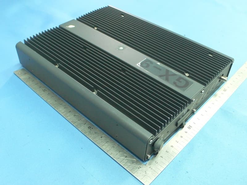
Click to zoom
Application Details
- Equipment Class
- TNB - Licensed Non-Broadcast Station Transmitter
- Date of Grant
- Feb 17, 2011
- Application Purpose
- Original Equipment
- Date of Application
- Feb 17, 2011
- Equipment Note
- Maritime User Terminal
- Frequency Range
- 1626.59500000 - 1660.20000000
- Company
- GLOCOM, INC.
- Country
- United States
Documents & Files
Document Text
Text extracted from the exhibit documents filed with the FCC. Open a document above to read the original.
Users Manual
Glocom GX-9 Operating Manual GLOCOM GX-9 Inmarsat Fleet Broadband Marine User Terminal Operating Manual Version 1.0 ii Glocom GX-9 Operating Manual SAFETY INFORMATION For your safety and protection, read this entire user manual before you attempt to use the Fleet Broadband Marine Satellite Terminal. In particular, read this safety section carefully. Keep this safety information where you can refer to it if necessary. WARNING SYMBOLS USED IN THIS MANUAL WARNING Potential radio Frequency (RF) hazard. Where you see this alert symbol and WARNING heading, strictly follow the warning instructions to avoid injury to eyes or other personal injury. WARNING Where you see this alert symbol and WARNING heading, strictly follow the warning instructions to avoid personal injury. DANGER Electric shock hazard: Where you see this alert symbol and DANGER heading, strictly follow the warning instructions to avoid electric shock injury or death. WARNINGS FOR SATELLITE TERMINAL DO NOT STAND IN FRONT OF THE ANTENNA This device emits radio frequency energy. To avoid injury, do not place head or other body parts in front of the satellite antenna when system is operational. Maintain a distance of two meters or more from the front of the Satellite Terminal antenna. PROPERLY GROUND THE EXTERNAL ANTENNA Failure to properly ground the optional external antenna may result in severe personal injury or death. Do not attempt to ground the optional external antenna unless you have the skills to do so in accordance with local electrical codes. DO NOT OPERATE DURING ELECTRICAL STORMS Operation of the Satellite Terminal during electrical storms may result in severe personal injury or death. Disconnect the Terminal from the computer and store the unit indoors if lightning is anticipated in the area of operation. Glocom GX-9 Operating Manual GENERAL Handle your Satellite Terminal with care. The enclosure is weather resistant per IEC 60529 IP54; however, do not submerge the unit or expose it to severe rain storms. Avoid exposing your Satellite Terminal to extreme hot or cold temperatures outside the range -25ºC to +60ºC. Avoid placing the Terminal close to cigarettes, open flames or any source of heat. Changes or modifications to the Terminal not expressly approved by Glocom Inc., could void your authority to operate this equipment. Only use a soft damp cloth to clean the Terminal. To avoid impaired Terminal performance, please ensure the unit’s antenna is not damaged or covered with foreign material like paint or labeling. When inserting the USIM/SIM, do not bend it or damage the contacts in any way. When connecting the interface cables, do not use excessive force. IN THE VICINITY OF BLASTING WORK AND IN EXPLOSIVE ENVIRONMENTS Never use the Satellite Terminal where blasting work is in progress. Observe all restrictions and follow any regulations or rules. Areas with a potentially explosive environment are often, but not always, clearly marked. Do not use the Terminal while at a petrol filling station. Do not use near fuel or chemicals. QUALIFIED SERVICE Do not attempt to disassemble your Satellite Terminal. The unit does not contain consumer-serviceable components. Only qualified service personnel may install or repair equipment. ACCESSORIES Use Glocom approved accessories only. Use of non-approved accessories may result in loss of performance, damage to the Satellite Terminal, fire, electric shock or injury. CONNECTING DEVICES Never connect incompatible devices to the Satellite Terminal. When connecting the Satellite Terminal to any other device, read the device’s User Manual for detailed safety instructions. iv Glocom GX-9 Operating Manual PACEMAKERS The various brands and models of cardiac pacemakers available exhibit a wide range of immunity levels to radio signals. Therefore, people who wear a cardiac pacemaker and who want to use a Satellite Terminal should seek the advice of their cardiologist. If, as a pacemaker user, you are still concerned about interaction with the Satellite Terminal, we suggest you follow these guidelines: Maintain a distance of 30 cm between the Terminal and your pacemaker; Maintain a distance of two meters from the front of the unit’s antenna; Refer to your pacemaker product literature for information on your particular device. If you have any reason to suspect that interference is taking place, turn off your Satellite Terminal immediately! HEARING AIDS Most new models of hearing aids are immune to radio frequency interference from Satellite Terminals that are more than 2 meters away. Many types of older hearing aids may be susceptible to interference, making it very difficult to use them near a Terminal. Should interference be experienced, maintain additional separation between you and the Satellite Terminal. Glocom GX-9 Operating Manual CONTENTS S AFETY INFORMATION ____________________________________________________ II Warning Symbols Used in this Manual ...................................................................... ii Warnings for Satellite Terminal .................................................................................... ii CONTENTS _______________________________________________________________ V INTRODUCTION ___________________________________________________________ 1 About This Product ........................................................................................................... 1 About This Operating Manual ...................................................................................... 1 Package Contents .............................................................................................................. 1 Minimum System Requirements for Laptop/PC ................................................... 2 GETTING STARTED ________________________________________________________ 3 Introduction to Getting Started ................................................................................... 3 Setting Up Your Terminal ........................…
Text truncated - open the document above for the full version.
External Photos
External photo
Internal Photos
Internal photo
RF Exposure Info
Calculation and sample for Confirmation Dear Reviewer, As specified in Table 1B of 47 CFR 1.1310 – Limits for Maximum Permissible Exposure(MPE), Limits for General Population/Uncontrolled Exposure: Frequency range (MHz)Power density (mW/cm²) 300 – 1,500 f/1500 1,500 – 100,000 1.0 The RF Exposure level is calculated using the general equation: S = PG/ 4πR 2 R=[PG/(4πS)] 0.5 where: S = power density (in appropriate units, e.g. mW/ cm2) P = power input to the antenna (in appropriate units, e.g., mW) G = power gain of the antenna in the direction of interest relative to an isotropic radiator R = distance to the center of radiation of the antenna (appropriate units, e.g., cm) Calculated Results: a) Calculated For WLAN: G=3.0dBi R=20cm Frequency(MHz) dBmmWG(dBi) NumericR(cm) S(mW/cm2) 241211.25 13.33521 3.02.0200.005293 243710.96 12.47384 3.02.0200.004951 246211.04 12.70574 3.02.0200.005043 So, the power density is kept. b) Calculated For BGAN: G=10.5dBi Frequency(MHz) dBmmW G(dBi) NumericLimit(mW/cm2) R(cm) 1626.59535.44 3499.45 10.5 11.2154.074089 1643.535.81 3810.66 10.5 11.2156.427292 1660.235.7 3715.35 10.5 11.2155.717191 So the antenna(s) used for this transmitter must be installed to provide a separation distance of at least 56.42 cm from all persons. c) Calculated For BGAN(for 2M distance): G=10.5dBi R=200cm Frequency(MHz) dBmmW G(dBi) NumericR(cm) S(mW/cm2) 1626.59535.44 3499.45 10.5 11.22000.078114 1643.535.81 3810.66 10.5 11.22000.0850607 1660.235.7 3715.35 10.5 11.22000.0829312 So, the power density is kept. Please contact us if you have any additional questions. Best Regards Morlab ZhangWenjie
Test Report
Report No.: SH10030058R01 Page 2 of 101 Table of Contents 1. TEST REPORT CERTIFICATION ......................................................................................... 4 2. GENERAL INFORMATION .................................................................................................... 5 2.1. Description Of EUT .................................................................................................................... 5 2.2. Test Standards and Results ........................................................................................................ 5 2.3. List of Equipments Used ............................................................................................................ 6 2.4. Test Facility ................................................................................................................................. 6 2.5. Environmental conditions .......................................................................................................... 6 2.6. Setup of Equipment Under Test ................................................................................................ 6 2.6.1. Description Of Support Units .................................................................................................... 6 2.6.2. EUT Operating Condition ......................................................................................................... 7 3. RF POWER OUTPUT TEST .................................................................................................... 8 1.1. Limits of RF Power Output ....................................................................................................... 8 1.2. Test Procedure ............................................................................................................................. 8 1.3. Test Setup .................................................................................................................................... 8 1.4. EUT Setup and Operating Conditions ...................................................................................... 8 1.5. Test Results .................................................................................................................................. 9 4. OCCUPIED BANDWIDTH TEST ......................................................................................... 32 2.1. Limit of Occupied Bandwidth Test ......................................................................................... 32 2.2. Test Procedure ........................................................................................................................... 32 2.3. Test Setup .................................................................................................................................. 32 2.4. Setup and Operating Conditions ............................................................................................. 32 2.5. Test Results ................................................................................................................................ 33 5. EMISSION LIMITATIONS PER FCC PART 25.202(F) ...................................................... 45 3.1. Limit ........................................................................................................................................... 45 3.2. Test Procedure ........................................................................................................................... 45 3.3. Setup of the RBW and Limit ................................................................................................... 45 3.4. Test Setup .................................................................................................................................. 47 3.5. EUT Setup and Operating Conditions .................................................................................... 47 3.6. Test Results ................................................................................................................................ 47 6. EMISSION LIMITATIONS PER FCC PART 25.216(H) ..................................................... 81 Report No.: SH10030058R01 Page 3 of 101 4.1. Limit ........................................................................................................................................... 81 4.2. Test Procedure ........................................................................................................................... 81 4.3. Test Setup .................................................................................................................................. 81 4.4. EUT Setup and Operating Conditions .................................................................................... 81 4.5. Test Results ................................................................................................................................ 82 7. FREQUENCY STABILITY MEASUREMENT .................................................................... 94 5.1. Limit ........................................................................................................................................... 94 5.2. Test Procedure ........................................................................................................................... 94 5.3. Test Setup .................................................................................................................................. 94 5.4. EUT Setup and Operating Conditions .................................................................................... 94 5.5. Test Results ................................................................................................................................ 95 APPENDIX I:PHOTOGRAPHS OF THE EUT ........................................................................... 98 APPENDIX II:PHOTOGRAPHS OF TEST CONFIGURATION ............................................ 101 Report No.:…
Text truncated - open the document above for the full version.
Test Setup Photos
Test Setup Photo
Contact Information
Applicant
Pan "JD" Chung-chun(Managing Director)
Test Firm
CCIC-SETQi Zhu
Technical Specifications
| # | Rule Parts | Frequency Range | Power Output | Emission | Tolerance |
|---|---|---|---|---|---|
| 2 | 25 | 1.63 GHz - 1.66 GHz | 3.811 W | 190KG1D | 10 ppm |