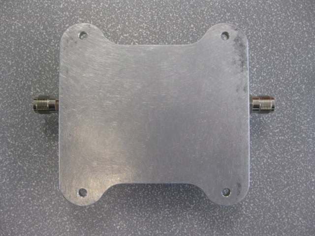
XS7WRE2710Dual-Band Bi-Directional Direct Connect Cellular Amplifier
Clear RF, LLC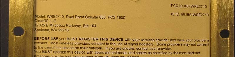
Click to zoom
Application Details
- Equipment Class
- B2W - Part 20 Wideband Consumer Booster (CMRS)
- Date of Grant
- May 19, 2014
- Application Purpose
- Original Equipment
- Date of Application
- Jan 07, 2014
- Equipment Note
- Dual-Band Bi-Directional Direct Connect Cellular Amplifier
- Frequency Range
- 1930.00000000 - 1990.00000000
- Company
- Clear RF, LLC
- Country
- United States
Documents & Files
Document Text
Text extracted from the exhibit documents filed with the FCC. Open a document above to read the original.
Users Manual
MAN-5446-001 Rev 6 WRE2710-S Operator’s Manual and Installation Guide: M2M –Machine to Machine Overview The WRE2710 Wireless Network Range Extender is a high performance, microprocessor controlled, bidirectional RF amplifier for the entire North American 850 MHz cellular and 1900 MHz PCS frequency bands. The amplifier has an automatic gain and oscillation control syst the gain and the output power if a signal anomaly occurs. This amplifier is designed to operate as a tethered (direct connect) unit within a cellular system, for maximum performance in weak signal coverage areas. The input power requirements for the amplifier are positive 8.0 to 36.0 volts DC (negative ground). This M2M kit includes an AC power adapter for use with typical household 120 volt AC power. Passive Bypass Technology The WRE2710 amplifier is equipped with ClearRF’s Passive Bypass technology. This feature allows the amplifier to passively bypass itself and become merely a pass through cable when amplification is not needed, during loss of power or when a faul Passive Bypass technology is useful in applications where the amplifier is mobile poor signal areas. The amplifier will bypass itself when close to cell towers, completely eliminating any potential for network disrupting noise power caused by too much amplific technology is also extremely useful in fire and security system installations where a connection with the antenna must always be maintained, even with loss of power. S Operator’s Manual and Installation Guide: Machine to Machine 0 Wireless Network Range Extender is a high performance, microprocessor controlled, bidirectional RF amplifier for the entire North American 850 MHz cellular and 1900 MHz PCS frequency bands. The amplifier has an automatic gain and oscillation control system that will automatically adjust the gain and the output power if a signal anomaly occurs. This amplifier is designed to operate as a tethered (direct connect) unit within a cellular system, for maximum performance in weak signal power requirements for the amplifier are positive 8.0 to 36.0 volts DC it includes an AC power adapter for use with typical household 120 volt Passive Bypass Technology – Patent Pending ped with ClearRF’s Passive Bypass technology. This feature allows the amplifier to passively bypass itself and become merely a pass through cable when amplification is not needed, during loss of power or when a fault is detected. is useful in applications where the amplifier is mobile, . The amplifier will bypass itself when close to cell towers, completely eliminating any potential for network disrupting noise power caused by too much amplification near a cell tower. The technology is also extremely useful in fire and security system installations where a connection with the antenna must always be maintained, even with loss of power. 1 ™ S Operator’s Manual and Installation Guide: 0 Wireless Network Range Extender is a high performance, microprocessor controlled, bidirectional RF amplifier for the entire North American 850 MHz cellular and 1900 MHz PCS frequency em that will automatically adjust the gain and the output power if a signal anomaly occurs. This amplifier is designed to operate as a tethered (direct connect) unit within a cellular system, for maximum performance in weak signal power requirements for the amplifier are positive 8.0 to 36.0 volts DC it includes an AC power adapter for use with typical household 120 volt ped with ClearRF’s Passive Bypass technology. This feature allows the amplifier to passively bypass itself and become merely a pass through cable when amplification is not , moving in and out of . The amplifier will bypass itself when close to cell towers, completely eliminating any ation near a cell tower. The technology is also extremely useful in fire and security system installations where a connection with the MAN-5446-001 Rev 6 Contents Overview ................................................................ Passive Bypass Technology – Patent Pending Parts List ................................................................ Installation Guide ................................ Installation with an SMA Device Installation with an MMCX Device Installation with an SMA Device LED Diagnostics ................................ Diagnostic LED definitions ................................ Optional Accessories ................................ WRE-2710 Specifications ................................ Safeguard Features................................ Antennas ................................................................ Warranty Information ................................ ................................................................................................ Patent Pending ................................................................ ................................................................................................ ................................................................................................................................ Installation with an SMA Device- Fixed Location ................................................................ Installation with an MMCX Device- Fixed Location ................................................................ Installation with an SMA Device- Mobile Location ................................................................ ................................................................................................................................ ................................................................................................ ................................................................................................ ................................................................................................ ................................................................................................ ..........................................................................................…
Text truncated - open the document above for the full version.
Attestation Statements
CKC Certification Services, LLC CB: US0103; NB: 0976 4933 Sierra Pines Drive Mariposa, CA 95338 Domestic Phone: 1 800-500-4EMC (4362) Domestic FAX: 1 866-779-9776 International Phone: +1 209-966-5240 International Fax: +1 858-300-5341 APP-FCC Page 1 of 8 Rev 1 APP-FCC CKC CS Application for Radio Equipment Certification in United States (FCC OET Form 731) Applicant/Grantee Information Company Name & Address: ClearRF, LLC 12825 E. Mirabeau Pkwy, Suite 104 Spokane Valley, WA 99216 Full Name: Pete Wilhite Title: Principal Engineer Email Address: [email protected] Telephone No: 509-321-9533 Facsimile No: 509-321-9510 Check here if this is a change in name and/or address not previously reported (See 47 CFR §2.929) Product Identification (FCC ID): FCC ID: XS7WRE2710 Application Details: Application Purpose Original Equipment CORES Information CKC CS FRN: 0005044755 Applicant FRN: 0020041091 For Change in FCC ID Only: Original FCC ID: FCC ID. Grant Date: Click to enter date. Product Description: (Description of product as marketed) Note: this text will appear on the Grant of Equipment Authorization Dual-Band Bi-Directional Direct Connect Cellular Amplifier Note: Max 50 characters. CKC Certification Services, LLC CB: US0103; NB: 0976 4933 Sierra Pines Drive Mariposa, CA 95338 Domestic Phone: 1 800-500-4EMC (4362) Domestic FAX: 1 866-779-9776 International Phone: +1 209-966-5240 International Fax: +1 858-300-5341 APP-FCC Page 2 of 8 Rev 1 Technical Contact Information Company Name & Address: ClearRF, LLC 12825 E. Mirabeau Pkwy, Ste 104 Spokane Valley, WA 99216 Full Name: Pete Wilhite Title: Principal Engineer Email Address: [email protected] Telephone No: 509-321-9533 Facsimile No: 509-321-9510 Non Technical Contact Information *If non-technical contact is the same as the technical contact, leave these items blank. Company Name & Address: CKC Certification Services, LLC 5046 Sierra Pines Dr Mariposa, CA 95338 Full Name: Randal Clark Title: TCB Manager Email Address: [email protected] Telephone No: 209-966-5240 Facsimile No: 866-779-9776 Test Firm Information Yes Is the test firm accredited? A2LA If yes, enter Accreditation Body 0803.02 If yes, enter Certificate Number Company Name & Address: CKC Laboratories, Inc. 110 North Olinda Place Brea, CA 92823 Full Name: Steve Behm Title: Director of Engineering Email Address: [email protected] Telephone No: 800-500-4362 Facsimile No: 866-779-9780 CKC Certification Services, LLC CB: US0103; NB: 0976 4933 Sierra Pines Drive Mariposa, CA 95338 Domestic Phone: 1 800-500-4EMC (4362) Domestic FAX: 1 866-779-9776 International Phone: +1 209-966-5240 International Fax: +1 858-300-5341 APP-FCC Page 3 of 8 Rev 1 Equipment Details / Specifications Yes / No Question Yes Does this application include a request for confidentiality for any portion(s) of the data contained in this application pursuant to 47 CFR §0.459 of the Commission Rules? No Does short-term confidentiality apply to this application? If Yes, specify the short-term confidentiality release date: Click here to enter a date. No Is there an equipment authorization waiver associated with this application? No If there is an equipment authorization waiver associated with this application, has the associated waiver been approved and all information uploaded? No Is this application for modular approval? If yes, enter the type of module: Choose an item. No Does this application include a Specific Absorption Rate (SAR) report for RF exposure compliance? No Is this application for software defined / cognitive radio authorization? No Is there a KDB (Knowledge Data Base) inquiry associated with this application? If yes, enter the inquiry tracking number: Click here to enter text. No Do you wish to defer the grant? (If product is approved, certification will not be made public until this date): Click here to enter a date. No Is the equipment in this application a composite device subject to an additional equipment authorization? No Is the equipment in this application part of a system that operates with, or is marketed with, another device that requires an equipment authorization? If either of the above questions is answered “yes”, complete the following statement: The related application: Choose an item. i. FCC ID: Click here to enter text. iii. FCC ID: Click here to enter text. ii. FCC ID: Click here to enter text. iv. FCC ID: Click here to enter text. CKC Certification Services, LLC CB: US0103; NB: 0976 4933 Sierra Pines Drive Mariposa, CA 95338 Domestic Phone: 1 800-500-4EMC (4362) Domestic FAX: 1 866-779-9776 International Phone: +1 209-966-5240 International Fax: +1 858-300-5341 APP-FCC Page 4 of 8 Rev 1 Equipment Specifications: Equipment Scope FCC Rule Part & Equipment Class* Frequency Range (MHz) Output Power (Watts) Frequency Tolerance Emissions Designator Microprocessor (Optional) Part 22H – B2W 824-849 0.48 AMP F9W CDMA Part 22H – B2W 869-894 0.0000085 AMP F9W CDMA Part 24E – B2W 1850-1910 0.39 AMP F9W CDMA Part 24E – B2W 1930-1990 0.0000051 AMP F9W CDMA Part 22H – B2W 824-849 0.48 AMP G7W EDGE Part 22H – B2W 869-894 0.0000085 AMP G7W EDGE Part 24E – B2W 1850-1910 0.39 AMP G7W EDGE Part 24E – B2W 1930-1990 0.0000051 AMP G7W EDGE Part 22H – B2W 824-849 0.45 AMP GXW GSM Part 22H – B2W 869-894 0.0000093 AMP GXW GSM Part 24E – B2W 1850-1910 0.30 AMP GXW GSM Part 24E – B2W 1930-1990 0.0000081 AMP GXW GSM Notes: For parts 11, 15 or 18 leave blank the Frequency Tolerance and Emissions Designator columns For parts 11, 15 or 18 except 15.247 and 15.407, leave blank the Output Power column * Rule Parts and Equipment classes drop-down is only a partial list. For other options, please contact CKC CS. Scope List (General): A1 - Low power transmitters on frequencies below 1 GHz (with the exception of spread spectrum devices), emergency alert systems, unintentional radiators (e.g., personal computers and associated peripherals and TV interface devices) and consumer ISM devices subject to certification (e.g.…
Text truncated - open the document above for the full version.
ID Label/Location Info
Proudly Manufactured in the USA FCC ID: XS7WRE2710 IC ID: 8918A-WRE2710 This device complies with Part 15 of the FCC rules. Operation is subject to the following two conditions: (1) this device may not cause harmful interference, and (2) this device must accept any interference received, including interference that may cause undesired operation. Model: WRE2710 Dual Band Cellular 850, PCS 1900 w/ Passive Bypass ClearRF 12825 E Mirabeau Parkway Spokane Valley, WA 99216 BEFORE USE you MUST REGISTER THIS DEVICE with your wireless provider and have your provider’s consent. Most wireless providers consent to teh use of signal boosters. Some providers may not consent to the use of this device on their network. If you are unsure, contact your provider. You MUST operate this device with approved antennas and cables as specified by the manufacturer. Antennas must be installed at least 20cm (8”) from any person. You MUST cease operating this device immediately if requested by the FCC or a licensed wireless service provider. WARNING. E911 location may not be provided or may be inaccuarate for calls serviced by using this device.
ID Label/Location Info
Proudly Manufactured in the USA FCC ID: XS7WRE2710 IC: 8918A-WRE2710 This device complies with Part 15 of the FCC rules. Operation is subject to the following two conditions: (1) this device may not cause harmful interference, and (2) this device must accept any interference received, including interference that may cause undesired operation. Model: WRE2710 Dual Band Cellular 850, PCS 1900 w/ Passive Bypass ClearRF 12825 E Mirabeau Parkway Spokane Valley, WA 99216 BEFORE USE you MUST REGISTER THIS DEVICE with your wireless provider and have your provider’s consent. Most wireless providers consent to teh use of signal boosters. Some providers may not consent to the use of this device on their network. If you are unsure, contact your provider. You MUST operate this device with approved antennas and cables as specified by the manufacturer. Antennas must be installed at least 20cm (8”) from any person. You MUST cease operating this device immediately if requested by the FCC or a licensed wireless service provider. WARNING. E911 location may not be provided or may be inaccuarate for calls serviced by using this device.
ID Label/Location Info
Proudly Manufactured in the USA FCC ID: XS7WRE2710 IC: 8918A-WRE2710 Model: WRE2710 Dual Band Cellular 850, PCS 1900 w/ Passive Bypass ClearRF 12825 E Mirabeau Parkway, Ste. 104 Spokane Valley, WA 99216 BEFORE USE you MUST REGISTER THIS DEVICE with your wireless provider and have your provider’s consent. Most wireless providers consent to the use of signal boosters. Some providers may not consent to the use of this device on their network. If you are unsure, contact your provider. You MUST operate this device with approved antennas and cables as specified by the manufacturer. Antennas must be installed at least 20cm (8”) from any person. You MUST cease operating this device immediately if requested by the FCC or a licensed wireless service provider. WARNING. E911 location may not be provided or may be inaccuarate for calls serviced by using this device. This is a consumer device This device complies with Part 15 of the FCC rules. Operation is subject to the following two conditions: (1) this device may not cause harmful interference, and (2) this device must accept any interference received, including interference that may cause undesired operation.
RF Exposure Info
Page 1 of 7 Report No: 94772-31 ADDENDUM TO RADIO FREQUENCY EXPOSURE TEST REPORT 94772-31 FOR THE Device: Dual-band Direct Connect Cellular Amplifier Model: WRE2710 Report No.: 94772-31A Date of issue: May 12, 2014 PREPARED FOR: Pete Wilhite 12825 E. Mirabeau Pkwy, Ste. 104 Spokane Valley, WA 99216 PREPARED BY: Randy Clark CKC Laboratories, Inc. 5046 Sierra Pines Drive Mariposa, CA 95338 The test data contained in this report documents the observed testing parameters pertaining to and are relevant for only the sample equipment tested in the agreed upon operational mode(s) and configuration(s) as identified herein. Compliance assessment remains the client’s responsibility. This report may not be used to claim product endorsement by A2LA or any government agencies. This test report has been authorized for release under quality control from CKC Laboratories, Inc. Steve Behm Director of Quality Assurance & Engineering Services CKC Laboratories, Inc. Page 2 of 7 Report No: 94772-31A Purpose: To demonstrate compliance with United States, Canada and/or European Union RF Exposure requirements for Portable equipment (devices used ≤20cm from the body) or Mobile equipment (devices used >20cm from the body) with power output below exemption levels and Mobile equipment, where Maximum Permissible Exposure (MPE) Calculations apply. Revision History Addendum A: To correct measured power level. United States Compliance Requirements (1.1310): RF Exposure Evaluation Limits Occupational / Controlled Exposure Frequency Range (MHz) Electric Field Strength (V/m) Magnetic Field Strength (A/m) Power Density (mW/cm 2 ) Averaging Time (minutes) 0.3-3.0 614 1.63 *(100) 6 3.0-30 1842/f 4.89/f *(900/f 2 ) 6 30-300 61.4 0.163 1 6 300-1500 --- --- f/300 6 1500-100,000 --- --- 5.0 6 RF Exposure Evaluation Limits General Population / Uncontrolled Exposure Frequency Range (MHz) Electric Field Strength (V/m) Magnetic Field Strength (A/m) Power Density (mW/cm 2 ) Averaging Time (minutes) 0.3-1.34 614 1.63 *(100) 30 1.34-30 824/f 2.19/f *(180/f 2 ) 30 30-300 27.5 0.073 0.2 30 300-1500 --- --- f/1500 30 1500-100,000 --- --- 1.0 30 * Plane wave equivalent power density Limit is calculated based on the mid-band frequency used in the operating frequency range. Exemption Level: Power output <60/f GHz (mW) Page 3 of 7 Report No: 94772-31 Canadian Compliance Requirements (RSS-102): RF Exposure Evaluation Limits Occupational / Controlled Exposure: Frequency Range (MHz) Electric Field Strength (V/m) Magnetic Field Strength (A/m) Power Density (W/m 2 ) Averaging Time (minutes) 0.003-1.0 600 4.9 --- 6 1.0-10 600/f 4.9/f --- 6 10-30 60 4.9/f --- 6 30-300 60 0.163 10 6 300-1500 3.54 f 0.5 0.0094*f 0.5 f/3 6 1500-15,000 137 0.364 50 6 15,000-150,000 137 0.364 50 616000/f 1.2 RF Exposure Evaluation Limits General Population / Uncontrolled Exposure Frequency Range (MHz) Electric Field Strength (V/m) Magnetic Field Strength (A/m) Power Density (W/m 2 ) Averaging Time (minutes) 0.003-1.0 280 2.19 --- 6 1.0-10 280/f 2.19/f --- 6 10-30 28 2.19/f --- 6 30-300 28 0.073 2 6 300-1500 1.585 * f 0.5 0.0042 * f 0.5 f/150 6 1500-15,000 61.4 0.163 10 6 15,000-150,000 61.4 0.163 10 616000/f 1.2 *Power density limit applicable >100MHz Exemption Level: Frequency Range (MHz) Maximum Output Power (Conducted or EIRP) 0.003-1000 ≤ 200 mW 1000-2200 ≤ 100 mW 2200-3000 ≤ 20 mW 3000-6000 ≤ 10 mW Page 4 of 7 Report No: 94772-31 European Union Compliance Requirements (ICNIRP): RF Exposure Evaluation Limits Occupational / Controlled Exposure: Frequency Range (MHz) Electric Field Strength (V/m) Magnetic Field Strength (A/m) Power Density (W/m 2 ) Averaging Time (minutes) 0.00082-0.065 610 24.4 --- 6 0.065-1.0 610 1.6/f --- 1.0-10 610/f 1.6/f --- 6 10-400 61 0.16 10 6 400-2000 3.0 * f 0.5 0.008 * f 0.5 f/40 6 2000-300,000 137 0.36 50 6 RF Exposure Evaluation Limits General Population / Uncontrolled Exposure Frequency Range (MHz) Electric Field Strength (V/m) Magnetic Field Strength (A/m) Power Density (W/m 2 ) Averaging Time (minutes) 0.003-0.150 87 5.0 --- 6 0.150-1.0 87 0.73/f -- 6 1.0-10 87/f 0.5 0.73/f --- 6 10-400 28 0.073 2 6 400-2000 1.375 f 0.5 0.0037*f 0.5 f/200 6 2000-300,000 61 0.16 10 6 *Power density limit applicable >100MHz Exemption Level: Power output < 20mW 1 Device and Antenna Operating Configuration: Device operating at maximum output power with continuous transmission of modulated data. Test Procedure: This equipment is evaluated in accordance with the guidelines set forth in OET Guide 65 & ANSI C95.1 for the US and Health Canada Safety Code 6 & RSS 102 for Canada. Other Considerations: Maximum antenna gain of 2.1dBi and including typical cable loss as described in the FCC Part 20 report. Calculations represent worst case. This report only addresses FCC 2.1091 RF exposure evaluation. Page 5 of 7 Report No: 94772-31 MPE Calculations Applicability: Limit Used X General Population / Uncontrolled Exposure Occupational / Controlled Exposure RF Exposure Exemption No United States NA Canada NA Europe Equipment operational details: Antenna Type / Configuration: Mag Whip Config # Operating Frequency (MHz) Measured Output Power (dBm) Antenna Gain (dBi) Cable Loss EIRP (dBm) 1 824-849 26.80 2.1 1.47 27.43 2 1850-1910 25.90 2.1 2.44 25.56 3 869-894 -20.30 2.1 1.47 -19.67 4 1930-1990 -20.90 2.1 2.44 -21.24 Measurements based from EMC Test Report(s): 94772-7 MPE Calculation: 2 4d EIRP DensityPower Given: EIRP in mW or W and d in cm or m Config # Distance (cm) US (1.1310) Canada (RSS-102) EU (ICNIRP) Power Density (mW/cm 2 ) Limit (mW/cm 2 ) Power Density (W/m 2 ) Limit (W/m 2 ) Power Density (W/m 2 ) Limit (W/m 2 ) 1 20 0.11 0.56 NA -- NA -- 2 20 0.07 1.00 NA -- NA -- 3 20 0.00 0.56 NA -- NA -- 4 20 0.00 1.00 NA -- NA -- Page 6 of 7 Report No: 94772-31 Summary: Exemptions: In the case the equipment meets compliance requirements by exemption the product is approved for use under mobile or portable conditions without further testing under the condition that any…
Text truncated - open the document above for the full version.
Test Report
This report contains a total of 27 pages and may be reproduced in full only. Partial reproduction may only be done with the written consent of CKC Laboratories, Inc. Clear RF, LLC TEST REPORT FOR ClearRF 25db Dual-Band Direct Connect Cellular Amplifier Model: WRE2710 Tested To The Following Standards: FCC Part 22H Report No.: 94772-8 Date of issue: December 19, 2013 This test report bears the accreditation symbol indicating that the testing performed herein meets the test and reporting requirements of ISO/IEC 17025 under the applicable scope of EMC testing for CKC Laboratories, Inc. We strive to create long-term, trust based relationships by providing sound, adaptive, customer first testing services. We embrace each of our customers’ unique EMC challenges, not as an interruption to set processes, but rather as the reason we are in business. Page 2 of 27 Report No.:94772-8 TABLE OF CONTENTS Administrative Information .......................................................................................................................... 3 Test Report Information ............................................................................................................................................ 3 Report Authorization ................................................................................................................................................. 3 Test Facility Information ............................................................................................................................................ 4 Software Versions ...................................................................................................................................................... 4 Site Registration & Accreditation Information .......................................................................................................... 4 Summary of Results ................................................................................................................................................... 5 Conditions During Testing.......................................................................................................................................... 5 Equipment Under Test ............................................................................................................................................... 6 Peripheral Devices ..................................................................................................................................................... 6 FCC Part 22H ................................................................................................................................................. 7 2.1049(I) Bandwidth Limitations ............................................................................................................................... 7 2.1051 / 22.917(a) - Spurious Emissions at Antenna Terminal ................................................................................ 16 2.1053 / 22.917(a) - Field Strength of Spurious Radiation ...................................................................................... 21 Supplemental Information .......................................................................................................................... 26 Measurement Uncertainty ...................................................................................................................................... 26 Emissions Test Details .............................................................................................................................................. 26 Page 3 of 27 Report No.:94772-8 ADMINISTRATIVE INFORMATION Test Report Information REPORT PREPARED FOR: REPORT PREPARED BY: Clear RF, LLC 12825 E Mirabeau Pkwy Ste 104 Spokane Valley, WA 99216 Morgan Tramontin CKC Laboratories, Inc. 5046 Sierra Pines Drive Mariposa, CA 95338 REPRESENTATIVE: Pete Wilhite Project Number: 94772 DATE OF EQUIPMENT RECEIPT: September 30, 2013 DATE(S) OF TESTING: September 30 - December 9, 2013 Report Authorization The test data contained in this report documents the observed testing parameters pertaining to and are relevant for only the sample equipment tested in the agreed upon operational mode(s) and configuration(s) as identified herein. Compliance assessment remains the client’s responsibility. This report may not be used to claim product endorsement by A2LA or any government agencies. This test report has been authorized for release under quality control from CKC Laboratories, Inc. Steve Behm Director of Quality Assurance & Engineering Services CKC Laboratories, Inc. Page 4 of 27 Report No.:94772-8 Test Facility Information Our laboratories are configured to effectively test a wide variety of product types. CKC utilizes first class test equipment, anechoic chambers, data acquisition and information services to create accurate, repeatable and affordable test results. TEST LOCATION(S): CKC Laboratories, Inc. 110 Olinda Place Brea, CA 92823 Software Versions CKC Laboratories Proprietary Software Version EMITest Emissions 5.00.14 Immunity 5.00.07 Site Registration & Accreditation Information Location CB # TAIWAN CANADA FCC JAPAN Brea A US0060 SL2-IN-E-1146R 3082D-1 90473 A-0147 Brea D US0060 SL2-IN-E-1146R 3082D-2 100638 A-0147 Page 5 of 27 Report No.:94772-8 SUMMARY OF RESULTS Standard / Specification: FCC Part 22H Description Test Procedure/Method Results Occupied Bandwidth FCC Part 2.1049(I) Pass Spurious Emissions at Antenna Terminal FCC Part 2.1051 / 22.917(a) Pass Field Strength of Spurious Radiation FCC Part 2.1053 / 22.917(a) Pass Conditions During Testing This list is a summary of the conditions noted for or modifications made to the equipment during testing. Summary of Conditions None Page 6 of 27 Report No.:94772-8 EQUIPMENT UNDER TEST (EUT) EQUIPMENT UNDER TEST ClearRF 25db dual-band direct connect cellular amplifier Manuf: Clear RF, LLC Model: WRE2710 Serial: 00…
Text truncated - open the document above for the full version.
Test Report
This report contains a total of 27 pages and may be reproduced in full only. Partial reproduction may only be done with the written consent of CKC Laboratories, Inc. Clear RF, LLC TEST REPORT FOR ClearRF 25db Dual-Band Direct Connect Cellular Amplifier Model: WRE2710 Tested To The Following Standards: FCC Part 24E Report No.: 94772-9 Date of issue: December 23, 2013 This test report bears the accreditation symbol indicating that the testing performed herein meets the test and reporting requirements of ISO/IEC 17025 under the applicable scope of EMC testing for CKC Laboratories, Inc. We strive to create long-term, trust based relationships by providing sound, adaptive, customer first testing services. We embrace each of our customers’ unique EMC challenges, not as an interruption to set processes, but rather as the reason we are in business. Page 2 of 27 Report No.:94772-9 TABLE OF CONTENTS Administrative Information .......................................................................................................................... 3 Test Report Information ............................................................................................................................................ 3 Report Authorization ................................................................................................................................................. 3 Test Facility Information ............................................................................................................................................ 4 Software Versions ...................................................................................................................................................... 4 Site Registration & Accreditation Information .......................................................................................................... 4 Summary of Results ................................................................................................................................................... 5 Conditions During Testing.......................................................................................................................................... 5 Equipment Under Test ............................................................................................................................................... 6 Peripheral Devices ..................................................................................................................................................... 6 FCC Part …
Text truncated - open the document above for the full version.
Contact Information
Applicant
SHAWN TAYLOR(Chief Operating Officer)
Technical Contact
Clear RF, LLCPete Wilhite
[email protected]509-321-9533
12825 E. Marabeau Pkwy · Spokane Valley, Washington · United States
Non-Technical Contact
CKC Certification Services, LLCRandy Clark
[email protected]209-966-5240
Test Firm
CKC Laboratories, Inc.Steve Behm
Technical Specifications
| # | Rule Parts | Frequency Range | Power Output | Emission | Tolerance |
|---|---|---|---|---|---|
| 16 | 24E | 1.93 GHz - 1.99 GHz | 8.10 µW | F9W | Amp |
Other Applications from Clear RF, LLC
XS7WRE2700
Nov 20, 2010RF Amplifier
Equipment Class
AMP - Amplifier