XTQ-SC200SC200 Wireless Scale
Medtronic Care Management Services, LLC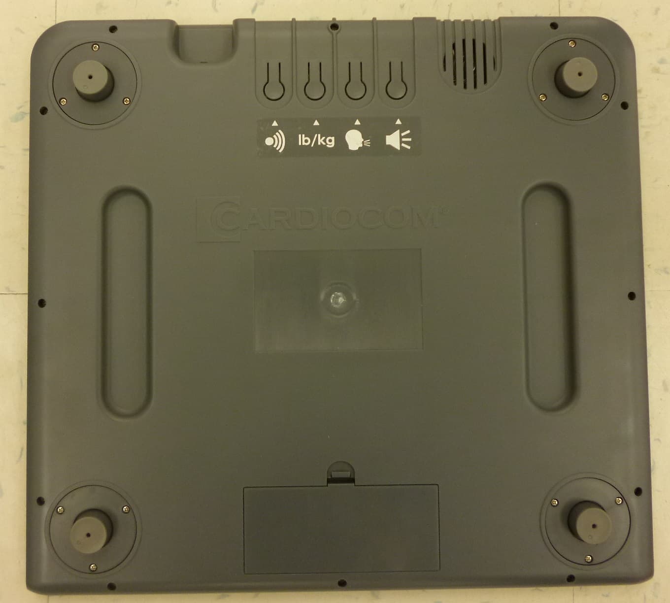
Click to zoom
Application Details
- Equipment Class
- DXX - Part 15 Low Power Communication Device Transmitter
- Date of Grant
- Aug 24, 2015
- Application Purpose
- Original Equipment
- Date of Application
- Aug 24, 2015
- Equipment Note
- SC200 Wireless Scale
- Frequency Range
- 2473.40000000 - 2478.70000000
- Country
- United States
Documents & Files
Document Text
Text extracted from the exhibit documents filed with the FCC. Open a document above to read the original.
Users Manual
(952)-361-6467 (USA) 1-888-243-8881 (USA and Canada) 00-800-1188-0000 (EU) Customer Care SC200 Scale User Manual Page 2 BEFORE USING THE SCALE WIRELESS EDITION™ (SCALE WE), READ THE ENTIRE USER MANUAL. The Scale Wireless Edition™ has been designed, manufactured and tested according to the highest quality standards. It is being provided to you by your health care team. You are required to return the Scale Wireless Edition™ upon request. The “crossed-out wheelie bin” symbol (shown on Page 24) on the device indicates it must not be disposed of with your normal household waste. Instead, return the products to Cardiocom for the recycling of waste electrical and electronic equipment. CARDIOCOM MAKES NO WARRANTY OF ANY KIND WITH REGARD TO THIS MATERIAL, INCLUDING, BUT NOT LIMITED TO, THE IMPLIED WARRANTIES OF MERCHANTABILITY AND FITNESS FOR A PARTICULAR PURPOSE. Cardiocom shall not be liable for errors contained herein or for incidental consequential damages in connection with the furnishings, performance or use of this material. This document contains proprietary information, which is protected by copyright. All rights are reserved. No part of this document may be photocopied, reproduced or translated without prior written consent of Cardiocom. WARNING: IF YOU FEEL UNSTEADY OR UNABLE TO STAND WITHOUT ASSISTANCE, DO NOT USE THE SCALE AND CONTACT YOUR HEALTH CARE TEAM FOR FURTHER DIRECTION. Page 3 To ensure the correct and safe use of the Scale Wireless Edition™ device (including all of its parts and peripherals), the following safety measures should be followed, along with the other warnings and cautions listed in this manual and on the device. Safety Terms Used DANGER Will cause serious injury or death. WARNING Could cause serious injury or death. CAUTION Will or could cause moderate or minor injury and/or property damage. IMPORTANT SCALE WIRELESS EDITION™ SAFETY PRECAUTIONS CARDIOCOM WILL NOT BE LIABLE FOR ANY HAZARDS INTRODUCED OR DAMAGE SUFFERED AS A RESULT OF UNAUTHORIZED MODIFICATION OF THE DEVICE OR FAILURE TO FOLLOW THE SAFETY PRECAUTIONS IN THIS MANUAL. Page 4 WARNING: Read all of the information in this manual before operating the Scale Wireless Edition™. Operate the Scale Wireless Edition™ as intended and do not use the device for any other purpose. The Scale Wireless Edition™ is intended for use by an adult. Children should not use the device or be left unattended with the Scale WE. Do not use the device if you are unable to operate it by yourself. The device is not to be used by persons who cannot express their intentions. Do not insert foreign objects into any openings of the Scale Wireless Edition™ or attempt to modify the device. If the product does not operate properly, exhibits an error or malfunctions in any way, stop use immediately, and request inspection and service. Failure to do so could result in the risk of an accident. If your device needs servicing, please call Customer Care number listed on the front page. The Scale Wireless Edition™ is designed to be maintained and serviced (with the exception of cleaning) only by qualified personnel. Do not disassemble or attempt to repair the device. The device is for indoor use only. Do not operate the Scale Wireless Edition™ in extreme temperature or humidity conditions. Do not expose the Scale Wireless Edition™ to water or other liquids. Doing so may cause short-circuiting, and other damage to the product. Do not modify or attempt to repair the Scale Wireless Edition™. Doing so could result in the risk of injury. Do not attempt to repair or open batteries. Remove the batteries from the device when there is a long delay between uses. Batteries that are not used for a long time have the potential to leak and cause an injury. Do not mix old and new batteries, batteries of different types, or batteries from different manufacturers. If battery fluid should get in your eyes, immediately flush your eyes with water and seek medical attention. Batteries are choking hazards for children under 3 years old. Do not allow children to play with the device. Page 5 CAUTION: Make sure to use the Scale Wireless Edition™ on a stable surface. Do not use the scale on carpet without the platform. If the Scale Wireless Edition™ becomes dirty, clean with a soft cloth that is slightly moistened with warm water. CaviCide® wipes can be used on the external surface if available. Do not use alcohol, paint thinner, or anything other than warm water or CaviCide® wipes. Use care in handling the Device. Do not drop the Device or any parts. Protect the Device from impact or sudden shocks. Store the Scale Wireless Edition™ in a clean, safe location. Do not store it in direct sunlight, high humidity, freezing temperatures or other extreme temperatures or dust. If you have questions about your Scale Wireless Edition™, call Customer Care for help. The number is listed on the front. Page 6 Table of Contents Scale Wireless Edition™ Overview .................................. 7 Setting Up the Scale Wireless Edition™ .......................... 9 Scale Wireless Edition™ Features ................................ 11 Taking a Weight ............................................................. 13 Changing the Volume .................................................... 15 Changing the Language ................................................. 16 Changing the Weight Measurement .............................. 17 Changing the Batteries .................................................. 18 Care and Cleaning Information ...................................... 20 Frequently Asked Questions .......................................... 21 Additional Information .................................................... 22 A B C D E F G H I J K Page 7 A Scale Wireless Edition™ Overview What is the Scale Wireless Edition™? The Scale Wireless Edition™ is a stand-alone digital weight scale that you can use in your home. It can partner with a Cardiocom product. How do you participate? Your healt…
Text truncated - open the document above for the full version.
External Photos
FCCID: XTQ-SC200
ID Label/Location Info
SC200 WIRELESS SCALE LABEL 3.69 IN. 2.2 IN.
Operational Description
SC200 Wireless Scale January 12, 2015 Compliant with FCC 15.203 rules The antenna used in the SC200 Wireless Scale is an off‐the‐shelf Antenova chip antenna model A5839. It is a chip antenna that gets soldered onto the board permanently. The SC200 Wireless Scale PCB is designed to only be used with Antenonva chip antenna A5839. Antenna: MFR: Antenova MPN: A5839 Description: Antenova RUFA chip antenna is intended for use with all 2.4 GHz applications.
Operational Description
Antennas for Wireless M2M Applications 1 Product Specification AE020157-O Rufa 2.4 GHz SMD Antenna Part No. A5839 / A5887 Product Specification 1 Features • Designed for 2.4 GHz applications: Bluetooth ® , Wi-Fi ® (802.11b/g), ZigBee ® , etc. • Easy to integrate • Low profile design for use with no ground beneath the antenna • High efficiency • Light weight • Intended for SMD mounting • Supplied in tape on reel 2 Description Rufa is intended for use with all 2.4 GHz applications. The antenna uses a ground plane in order to radiate efficiently, but this ground plane must not extend underneath the antenna itself. The antenna is available in two versions with the feed locations on the right or left hand side of the antenna. 3 Applications • Mobile phones • PDAs • PNDs • Headsets • PMPs / MP3s • Laptops • PC-Cards • Sensors Rufa 2.4 GHz SMD Antenna Part No. A5839 / A5887 Antennas for Wireless M2M Applications 2 Product Specification AE020157-O 4 Part numbers Rufa Left: A5839 Rufa Right: A5887 150 5 General data 6 Electrical characteristics Typical performance Conditions Peak gain 2.1 dBi All data measured on Antenova’s reference boards, part numbers A5839-U1 and A5887-U1 Data given for the 2.4 – 2.5 GHz frequency range Average gain -1.2 dBi Average efficiency 75% Maximum Return Loss -11 dB Maximum VSWR 1.8:1 Product name Rufa 2.4 GHz Part Number A5839 (Left) A5887 (Right) Frequency 2.4 – 2.5 GHz Polarization Linear Operating temperature -40 ºC to +85 ºC Impedance with matching 50 Ω Weight 0.1 g Antenna type SMD Dimensions 12.8 x 3.9 x 1.1 [mm] Rufa 2.4 GHz SMD Antenna Part No. A5839 / A5887 Antennas for Wireless M2M Applications 3 Product Specification AE020157-O 7 Electrical performance 7- 1 Return Loss 2200 2300 2400 2500 2600 2700 -40 -30 -20 -10 0 ∇ ∇ [MHz] [dB] 7- 2 VSWR 2200 2300 2400 2500 2600 2700 1 2 3 4 5 ∇ ∇ [MHz] Rufa 2.4 GHz SMD Antenna Part No. A5839 / A5887 Antennas for Wireless M2M Applications 4 Product Specification AE020157-O 7- 3 Antenna patterns Z X Y XY plane ZY plane XZ plane Patterns show combined polarisations measured on reference board A5839-U1 Rufa 2.4 GHz SMD Antenna Part No. A5839 / A5887 Antennas for Wireless M2M Applications 5 Product Specification AE020157-O 8 Antenna dimensions Rufa Left Rufa Right L W H Length Width Height 12.8 ± 0.2 3.9 ± 0.2 1.1 ± 0.2 Dimensions in mm 9 Antenna footprint Rufa Left (Part No: A5839) Rufa Right (Part No: A5887) * CAD files of the antenna footprint are available from Antenova M2M on request. Please contact [email protected] for further details. I S K J N L O 1.0 ± 0.1 2.0 ± 0.1 8.1 ± 0.1 3.7 ± 0.1 1.3 ± 0.1 2.4 ± 0.1 0.5 ± 0.1 Dimensions in mm Rufa 2.4 GHz SMD Antenna Part No. A5839 / A5887 Antennas for Wireless M2M Applications 6 Product Specification AE020157-O 10 Electrical interface 10-1 Transmission lines • All transmission lines should be designed to have a characteristic impedance of 50 Ω • The length of the transmission lines should be kept to a minimum • Any other parts of the RF system like transceivers, power amplifiers, etc, should also be designed to have an impedance of 50 Ω Once the material for the PCB has been chosen (PCB thickness and dielectric constant), a coplanar transmission line can easily be designed using any of the commercial software packages for transmission line design. For the chosen PCB thickness, copper thickness and substrate dielectric constant, the program will calculate the appropriate transmission line width and gaps on either side of the track so the characteristic impedance of the coplanar transmission line is 50 Ω. 10-2 Matching circuit The antenna requires a matching circuit that must be optimized for each customer’s product. The matching circuit will require up to three components and the following pad layout should be designed into the device so the correct circuit can be installed: The antenna feed pad and the antenna ground pad are indicated in the drawing above. Additional pads are for mechanical attachment only and should not be grounded. Rufa 2.4 GHz SMD Antenna Part No. A5839 / A5887 Antennas for Wireless M2M Applications 7 Product Specification AE020157-O In addition to the matching circuit, a separate DC blocking capacitor will also be required between the radio and the antenna matching circuit. Note: The component values for the matching circuit will vary depending on the size of the PCB and surrounding components. The impedance of the antenna should be measured before selecting suitable matching components. Antenova M2M offers this service on request. Contact [email protected] for further information. 10-3 Antenna placement Antenova M2M strongly recommends placing the antenna near the edge of the board. Maximum antenna performance is achieved by placing the antenna towards one of the corners of the PCB and with the feed point of the antenna as close to same corner of the PCB as possible. Additional ground and components near the antenna should be at a distance of at least 2 mm. Where possible the antenna should be clear of ground from both sides, although the antenna can work well with a minimum clearance of D ≥ 2 mm as shown in the drawing above. Rufa 2.4 GHz SMD Antenna Part No. A5839 / A5887 Antennas for Wireless M2M Applications 8 Product Specification AE020157-O 10-4 Reference boards The reference boards have been designed for evaluation purposes of Rufa 2.4 GHz and they include a SMA female connector Rufa Left Rufa Right Dimensions in mm To order a reference board contact [email protected] . Rufa 2.4 GHz SMD Antenna Part No. A5839 / A5887 Antennas for Wireless M2M Applications 9 Product Specification AE020157-O 11 Soldering This antenna is suitable for lead free soldering. The reflow profile should be adjusted to suit the device, oven and solder paste, while observing the following conditions: - The maximum temperature should not exceed 240 ºC - However for lead free soldering, a maximum temperature of 255 ºC for no more than 20 seconds is permitted. -…
Text truncated - open the document above for the full version.
Test Report
This report must not be used to claim product certification, approval, or endorsement by NVLAP, NIST, or any agency of the federal government of the United States of America. This Report may only be duplicated in its entirety Cardiocom SC200 Wireless Scale FCC 15.249:2015 Report # CCOM0008 Rev. 1 NVLAP Lab Code: 200881-0 CERTIFICATE OF TEST 2014-12-10 Product compliance is the responsibility of the client; therefore, the tests and equipment modes of operation represented in this report were agreed upon by the client, prior to testing. The results of this test pertain only to the sample(s) tested. The specific description is noted in each of the individual sections of the test report supporting this certificate of test. Last Date of Test: January 02, 2015 Cardiocom Model: SC200 Wireless Scale Radio Equipment Testing Standards Specification Method FCC 15.249:2015 ANSI C63.10:2009 Results Method Clause Test Description Applied Results Comments 6.2 AC Powerline Conducted Emissions No N/A Battery powered, not applicable. 6.5, 6.6 Field Strength of Fundamental Yes Pass 6.5, 6.6 Field Strength of Harmonics and Spurious Radiated Emissions Yes Pass Deviations From Test Standards None Approved By: Tim O'Shea, Operations Manager Report No. CCOM0008 Rev. 12/14 REVISION HISTORY REV 2014.10.14 Revision Number Description Date Page Number 00 None 01 Changed the EUT Name 2/20/2015 1, 2, 7, 11, 13, 14 Report No. CCOM0008 Rev. 13/14 ACCREDITATIONS AND AUTHORIZATIONS REV 2014.10.08 United States FCC - Designated by the FCC as a Telecommunications Certification Body (TCB). Certification chambers, Open Area Test Sites, and conducted measurement facilities are listed with the FCC. A2LA - Accredited by A2LA to ISO / IEC Guide 65 as a product certifier. This allows Northwest EMC to certify transmitters to FCC and IC specifications. NVLAP - Each laboratory is accredited by NVLAP to ISO 17025 Canada IC - Recognized by Industry Canada as a Certification Body (CB). Certification chambers and Open Area Test Sites are filed with IC. European Union European Commission – Validated by the European Commission as a Conformity Assessment Body (CAB) under the EMC directive and as a Notified Body under the R&TTE Directive. Australia/New Zealand ACMA - Recognized by ACMA as a CAB for the acceptance of test data. Korea MSIP / RRA - Recognized by KCC’s RRA as a CAB for the acceptance of test data. Japan VCCI - Associate Member of the VCCI. Conducted and radiated measurement facilities are registered. Taiwan BSMI – Recognized by BSMI as a CAB for the acceptance of test data. NCC - Recognized by NCC as a CAB for the acceptance of test data. Singapore IDA – Recognized by IDA as a CAB for the acceptance of test data. Israel MOC – Recognized by MOC as a CAB for the acceptance of test data. Hong Kong OFTA – Recognized by OFTA as a CAB for the acceptance of test data. Vietnam MIC – Recognized by MIC as a CAB for the acceptance of test data. SCOPE For details on the Scopes of our Accreditations, please visit: http://www.nwemc.com/accreditations/ Report No. CCOM0008 Rev. 14/14 MEASUREMENT UNCERTAINTY TMU.2014.12.03 Measurement Uncertainty When a measurement is made, the result will be different from the true or theoretically correct value. The difference is the result of tolerances in the measurement system that cannot be completely eliminated. To the extent that technology allows us, it has been our aim to minimize this error. Measurement uncertainty is a statistical expression of measurement error qualified by a probability distribution. A measurement uncertainty estimation has been performed for each test per our internal quality document WP 342. The estimation is used to compare the measured result with its "true" or theoretically correct value. The expanded measurement uncertainty (K=2) for each test is on each data sheet. Our measurement data meets or exceeds the measurement uncertainty requirements of the applicable specification; therefore, the test data can be compared directly to the specification limit to determine compliance. The calculations for estimating measurement uncertainty are based upon ETSI TR 100 028 (or CISPR 16-4-2 as applicable), and are available upon request. The following table represents the Measurement Uncertainty (MU) budgets for each of the tests that may be contained in this report. Test + MU - MU Frequency Accuracy (Hz) 0.0007% -0.0007% Amplitude Accuracy (dB) 1.2 dB -1.2 dB Conducted Power (dB) 0.3 dB -0.3 dB Radiated Power via Substitution (dB) 0.7 dB -0.7 dB Temperature (degrees C) 0.7°C -0.7°C Humidity (% RH) 2.5% RH -2.5% RH Voltage (AC) 1.0% -1.0% Voltage (DC) 0.7% -0.7% Field Strength (dB) 4.7 dB -4.7 dB AC Powerline Conducted Emissions (dB) 2.9 dB -2.9 dB Report No. CCOM0008 Rev. 15/14 FACILITIES REV 2015.1.05 California Labs OC01-13 41 Tesla Irvine, CA 92618 (949) 861-8918 Minnesota Labs MN01-08, MN10 9349 W Broadway Ave. Brooklyn Park, MN 55445 (612)-638-5136 New York Labs NY01-04 4939 Jordan Rd. Elbridge, NY 13060 (315) 685-0796 Oregon Labs EV01-12 22975 NW Evergreen Pkwy Hillsboro, OR 97124 (503) 844-4066 Texas Labs TX01-09 3801 E Plano Pkwy Plano, TX 75074 (469) 304-5255 Washington Labs NC01-05 19201 120 th Ave NE Bothell, WA 9801 (425)984-6600 NVLAP NVLAP Lab Code: 200676-0 NVLAP Lab Code: 200881-0 NVLAP Lab Code: 200761-0 NVLAP Lab Code: 200630-0 NVLAP Lab Code:201049-0 NVLAP Lab Code: 200629-0 Industry Canada 2834B-1, 2834B-3 2834E-1 N/A 2834D-1, 2834D-2 2834G-1 2834F-1 BSMI SL2-IN-E-1154R SL2-IN-E-1152R N/A SL2-IN-E-1017 SL2-IN-E-1158R SL2-IN-E-1153R VCCI A-0029 A-0109 N/A A-0108 A-0201 A-0110 Report No. CCOM0008 Rev. 16/14 PRODUCT DESCRIPTION 2014-12-10 Client and Equipment Under Test (EUT) Information Company Name: Cardiocom Address: 7980 Century Blvd City, State, Zip: Chanhassen, MN 55317 Test Requested By: Viet Vuong Model: SC200 Wireless Scale First Date of Test: January 02, 2015 Last Date of Test: January 02, 2015 Receipt Date of Samples: January 02, 2015 Equipment Design Stage: …
Text truncated - open the document above for the full version.
Test Setup Photos
photo SRE1.jpg SRE2.jpg FIELD STRENGTH OF FUNDAMENTAL PSA-ESCI 2014.09.10 photo SRE3.jpg FIELD STRENGTH OF FUNDAMENTAL PSA-ESCI 2014.09.10 photo SRE1.jpg SRE2.jpg FIELD STRENGTH OF HARMONICS AND SPURIOUS RADIATED EMISSIONS PSA-ESCI 2014.09.10 photo SRE3.jpg FIELD STRENGTH OF HARMONICS AND SPURIOUS RADIATED EMISSIONS PSA-ESCI 2014.09.10 photo SRE1.jpg SRE2.jpg FIELD STRENGTH OF HARMONICS AND SPURIOUS RADIATED EMISSIONS PSA-ESCI 2014.09.10 photo SRE3.jpg FIELD STRENGTH OF HARMONICS AND SPURIOUS RADIATED EMISSIONS PSA-ESCI 2014.09.10
Contact Information
Applicant
Chris Abrahamson(Director CMS R&D)
Test Firm
Northwest EMC, Inc.Greg Kiemel
Technical Specifications
| # | Rule Parts | Frequency Range | Power Output |
|---|---|---|---|
| 1 | 15C | 2.47 GHz - 2.48 GHz | - |