XUJDBSBLTHDBScar
Launch Tech Co., Ltd.Application Details
- Equipment Class
- DSS - Part 15 Spread Spectrum Transmitter
- Date of Grant
- Jun 17, 2012
- Application Purpose
- Original Equipment
- Date of Application
- Jun 17, 2012
- Equipment Note
- DBScar
- Frequency Range
- 2402.00000000 - 2480.00000000
- Company
- Launch Tech Co., Ltd.
- Country
- China
Documents & Files
Document Text
Text extracted from the exhibit documents filed with the FCC. Open a document above to read the original.
Users Manual
- 1 -- 2 -- 3 -- 4 -- 5 -- 6 -- 7 -- 8 -- 9 - LAUNCHLAUNCHLAUNCHLAUNCHLAUNCHLAUNCHLAUNCHLAUNCHLAUNCHLAUNCHLAUNCHLAUNCHLAUNCHLAUNCH DBScar User's Manual (V1.0) LAUNCH TECH. CO., LTD. Launch Industrial Park, North of Wuhe Avenue, Banxuegang, Longgang, Shenzhen, Guangdong, P.R.China, 518129 Tel: +86-755-84528767 http://www.cnlaunch.com http://www.crecorder.com http://www.dbscar.com Thanks for your purchasing our products. Before operating, please carefully read the “Disclaimer” on the last page of this user’s manual. 1. Intruduction DBScar is a new diagnostic Telematics product for automobile aftermarket. With excellent performance and powerful functions, it can diagnose all electrical control system of vehicls equipped with OBD2 16 PIN connector and is compatible with most of LAUNCH’s bluetooth diagnostic device. DBScar provides an Micro USB port and an OBD-16 diagnostic socket. Data communication and firmware upgrade can be done via bluetooth and USB. on DBScar stands for Car Cloud logo. Car Cloud is an state-of-an-art individual application product, which is developed based on our LAUNCH’s diagnostic devices and technology service platform with independent intellectual property rights, mainly providing professional, intelligent vehicle monitoring and diagnosing service for car owners. 2. Product Components 2.1. Ports & Indicators 1 2 3 4 Fig.1-1 Product illustration No.Name & Functions 1 OBD-16 diagnostic connector: t o c o n n e c t v e h i c l e ’ s O B D 2 diagnostic socket. 2 Power indicator 3 Communication indicator 4 Micro USB port: to connect to PC or LAUNCH’s diagnostic device via USB cable. 4. Connections 1) Locate vehicle’s DLC socket: it provides standard 16 pins and is generally located on driver’s side, about 12 inch away from the center of dashboard. See Fig. 4-1. If no DLC is found, please refer to automobile repair manual. 2) Plug the DBScar into DLC socket and the power indicator on DBScar will light up. on your phone via bluetooth, then use mobile internet to send diagnostic report to repair garage for fault processing and analysis. 6. Installing Software Visit http://www.dbscar.com to download DBScar software to your phone, and click it to install. (The method of installing this software is same as that of installing other phone applications. For details, please refer to user’s manual for your phone.) ! While installing, do not attempt to delete data or format SD card. Otherwise, the application may fail to run. 7. Bluetooth Setting To operate software, bluetooth must be paired and linked, or else you can not obtain any data. Meanwhile, please make sure the communication distance between your phone and DBScar is kept within 10 meters. 1. Enter bluetooth setting interface of your phone, turn bluetooth ON and scan for devices, the system will list out the search result. Highlight and 2.2. Accessories Please check the following accessories: 1) DBScar x 1 ; 2) DBScar user’s manual x 1 3. Technical Specifications Working voltage: 9~15V Working current: <600mA Working temp: -10 to 55°C (32 to 122 F°) Storage temp: -20 to 70°C (-4 to 158 F°) Storage humidity: <80% Working humidity: <60% and the communication indicator on DBScar will blink. For details, please refer to user’s manual included with diagnostic tool. Note: For devices named with DBS_ username, refer to “On Password”. 5.2 Mobile phones with diagnostic software This mode applies to individuals. 5.2.1 Diagnosing on phones To perform this function, please download and install car cloud client software on your phone. Then make bluetooth settings and communicate with DBScar via bluetooth, sending diagnostic result saved in DBScar to client software for review. (For “Installing Software” and “Bluetooth Setting”, please refer to Chapter 6 & 7.) 5.2.2 Data recording DBScar can work as a real-time monitor device for recording vehicle's working status, then send the data to PC client software via USB cable for analysis. Alternatively, users also can transmit the data to car cloud client software installed Near the center of dashboard Fig. 4-1 5. Using DBScar DBScar can be applied to: 5.1 Bluetooth diagnostic devices This mode applies to repair garages. When one car owner drives his/her car equipped with a DBScar to a garage, vehicle maintainer can use LAUCH's diagnostic tool to diagnose your car rapidly. 1. Make sure vehicle has been energized or ignition has been turned on; 2. Activate bluetooth of diagnostic tool and scan for other bluetooth devices. If DBS LAUNCH_DBScar (default bluetooth name) in the search result list is found, click it to start diagnosing click the desired one (the default name is DBS LAUNCH_DBScar, which can be revised while registering DBScar. Note: The serial No. of DBScar enclosure is used to bind to phone or other personal application software. DBScar may bind to multiple phones, but one phone is suggested to manage one DBScar only. 2. If it is the first time for you to match, a dialog box will appear. Input default password 0000 and click “OK” to finish pairing. 3. Click on your phone to run it, then enter the main menu and click the desired diagnosing icon. 4. A dialog box will appear, prompting it can be performed only when bluetooth is linked. Click “YES” . 5. Choose the paired device and link it. Note: After you set or change bluetooth pair, the system will reset automatically and enter the main menu. 8. Upgrading Update can be done via USB or bluetooth. After DBScar is energized and properly connected to supporting device, the system attention to the following: • Follow instructions to install DBScar into your vehicle before using. • While you are driving a car, do not attempt to operate this product, so as to avoid distraction and traffic hazard; The company assumes no responsibilities for any traffic accident or economic loss resulting from operating it while driving. • This product collects and sends data via bluetooth communication. Avoid using this product near a place with strong elect…
Text truncated - open the document above for the full version.
Cover Letter(s)
SCS-F19: Confidentiality Request Letter Page 1 of 1 Rev 2.0 Launch Tech Co., Ltd. June 5, 2012 To: Federal Communications Commission Authorization and Evaluation Division 7435 Oakland Mills Road Columbia, MD Confidentiality Request regarding application for certification of FCC ID: XUJDBSBLTH We hereby request confidential treatment of information accompanying this application as outlined below: - Block Diagram - Operational Description - Schematic The above materials contain trade secrets and proprietary information not customarily released to the public. The public disclosure of these materials may be harmful to the applicant and provide unjustified benefits to its competitors. The applicant understands that pursuant to Section 0.457 & 0.459 of the Rules, disclosure of this application and all accompanying documentation will not be made before the date of the Grant for this application. Client’s signature : Client’s name / title : Yibing Xue/ Manager Contact information / address : Launch Industrial Park, North of W uhe Rd., Banxuegang, Longgang, Shenzhen, China
ID Label/Location Info
FCC ID: XUJDBSBLTH This device complies with Part 15 of the FCC Rules. Operation is subject to the following two conditions: (1) this device may not cause harmful interference, and (2) this device must accept any interference received, including interference that may cause undesired operation.
ID Label/Location Info
FCC Certification Label Location Sample
Internal Photos
Antenna
RF Exposure Info
FCC ID : XUJDBSBLTH 1. RF EXPOSURE 1.1. The Requirement System operating under the provisions of this section shall be operated in a manner that ensures that the public is not exposed to radio frequency energy levels in excess of the Commission’s guidelines. See Section 15.247(b)(4) and Section 1.1307(b)(1) 1.2. Limit For Maximum Permissible Exposure (MPE) Limits for General Population/ Uncontrolled Exposure F = frequency in MHz, * Plane-wave equivalent power density 1.3. MPE Calculations E(V/m) = 30 P G d , Power Density: S( 2 mW/cm) = 2 377 E Where E = Electric Field (V/m) P = Peak Output Power (mW) G = Antenna Numeric Gain (numeric) = 10 x , x = Antenna Gain(dBi) /10 d = Separation Distance (cm) Frequency Range (MHz) Electric Field Strength (E) (V/m) Magnetic Field Strength (H) (A/m) Power Density (S) ( 2 mW/cm) Averaging Time 2 E, 2 H or S (minutes) 0.3-1.34 614 1.63 (100)* 30 1.34-30 824/f 2.19/f (180/f)* 30 30-300 27.5 0.073 0.2 30 300-1500 f/1500 30 1500-100,000 1.0 30 We can change the formula to: S = 2 30 377 PG d or, d = 30 377 PG S Because the EUT is belong to general population/uncontrolled exposure. So 1.3.1. We considering the limit of minimum separation distance (d) is 20cm, Maximum Output Power = 0.052mW Antenna Gain = 2.0(dBi) = 1.58(numeric) S = 2 30 377 PG d = 0.00002 2 mW/cm < 1.0 2 mW/cm (limit) Calculated RF Exposure power density is 0.00002 2 mW/cm , less than the limit. 1.3.2. We considering the limit of power density (S) is 1.0 2 mW/cm , Maximum Output Power = 0.052mW Antenna Gain = 2.0(dBi) = 1.58(numeric) d = 30 377 PG S = 0.081 cm < 20 cm Calculated RF Exposure separation distance is 0.081 cm, less than the minimum separation distance 1.3.3.FCC Radiation Exposure Statement This equipment complies with FCC radiation exposure limits set forth for an uncontrolled environment. In order to avoid the possibility of exceeding the FCC radio frequency exposure limits, Human proximity to the antenna shall not be less than 20cm(8 inches) during normal operation. Proposed RF exposure safety information to include in User’s Manual. This equipment shall not be used in Portable mode
Test Report
Page 1 of 82 FCC ID: XUJDBSBLTH ACCURATE TECHNOLOGY CO. LTD Report No.: ATE20120881 APPLICATION CERTIFICATION On Behalf of Launch Tech Co., Ltd. DBScar Model No.: DBScar FCC ID: XUJDBSBLTH Prepared for : Launch Tech Co., Ltd. Address : Launch Industrial Park, North of Wuhe Rd., Banxuegang, Longgang, Shenzhen, China Prepared by : ACCURATE TECHNOLOGY CO. LTD Address : F1, Bldg. A, Changyuan New Material Port, Keyuan Rd. Science & Industry Park, Nanshan, Shenzhen, Guangdong P.R. China Tel: (0755) 26503290 Fax: (0755) 26503396 Report Number : ATE20120881 Date of Test : May 17, 2012 Date of Report : June 5, 2012 Page 2 of 82 FCC ID: XUJDBSBLTH ACCURATE TECHNOLOGY CO. LTD Report No.: ATE20120881 TABLE OF CONTENTS Description Page Test Report Certification 1. GENERAL INFORMATION .......................................................................................................... 5 1.1. Description of Device (EUT)....................................................................................................................5 1.2. Special Accessory and Auxiliary Equipment ...........................................................................................5 1.3. Description of Test Facility ......................................................................................................................6 1.4. Measurement Uncertainty.........................................................................................................................6 2. MEASURING DEVICE AND TEST EQUIPMENT ..................................................................... 7 3. OPERATION OF EUT DURING TESTING ................................................................................. 8 3.1. Operating Mode ........................................................................................................................................8 3.2. Configuration and peripherals ..................................................................................................................8 4. TEST PROCEDURES AND RESULTS ......................................................................................... 9 5. 20DB BANDWIDTH TEST............................................................................................................10 5.1. Block Diagram of Test Setup..................................................................................................................10 5.2. The Requirement For Section 15.247(a)(1) ............................................................................................10 5.3. EUT Configuration on Measurement .....................................................................................................10 5.4. Operating Condition of EUT ..................................................................................................................10 5.5. Test Procedure ........................................................................................................................................11 5.6. Test Result ..............................................................................................................................................11 6. CARRIER FREQUENCY SEPARATION TEST........................................................................ 15 6.1. Block Diagram of Test Setup..................................................................................................................15 6.2. The Requirement For Section 15.247(a)(1) ............................................................................................15 6.3. EUT Configuration on Measurement .....................................................................................................15 6.4. Operating Condition of EUT ..................................................................................................................15 6.5. Test Procedure ........................................................................................................................................16 6.6. Test Result ..............................................................................................................................................16 7. NUMBER OF HOPPING FREQUENCY TEST ......................................................................... 20 7.1. Block Diagram of Test Setup..................................................................................................................20 7.2. The Requirement For Section 15.247(a)(1)(iii) ......................................................................................20 7.3. EUT Configuration on Measurement .....................................................................................................20 7.4. Operating Condition of EUT ..................................................................................................................20 7.5. Test Procedure ........................................................................................................................................21 7.6. Test Result ..............................................................................................................................................21 8. DWELL TIME TEST ..................................................................................................................... 25 8.1. Block Diagram of Test Setup..................................................................................................................25 8.2. The Requirement For Section 15.247(a)(1)(iii) ......................................................................................25 8.3. EUT Configuration on Measurement .....................................................................................................25 8.4. Operating Condition of EUT ..................................................................................................................25 8.5. Test Procedure ................................................…
Text truncated - open the document above for the full version.
Test Setup Photos
Conducted emission test Radiated emission test 9kHz-30MHz 30MHz-1GHz Above 1GHz
Contact Information
Applicant
Ivy Zhong(Manager)
Test Firm
Accurate Technology Co., Ltd.Sean Liu
Technical Specifications
| # | Rule Parts | Frequency Range | Power Output |
|---|---|---|---|
| 1 | 15C | 2.40 GHz - 2.48 GHz | 52.00 µW |
Other Applications from Launch Tech Co., Ltd.
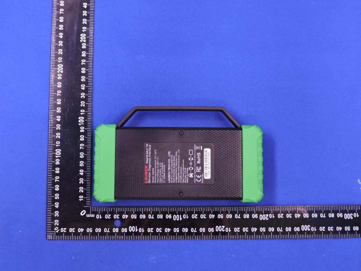
XUJS4006
Sep 04, 2026Remote Diagnosis Interface
Equipment Class
DTS - Digital Transmission SystemXUJEVT511S
Jul 09, 2026Battery Pack Airtightness Tester (High Voltage)
Equipment Class
DTS - Digital Transmission System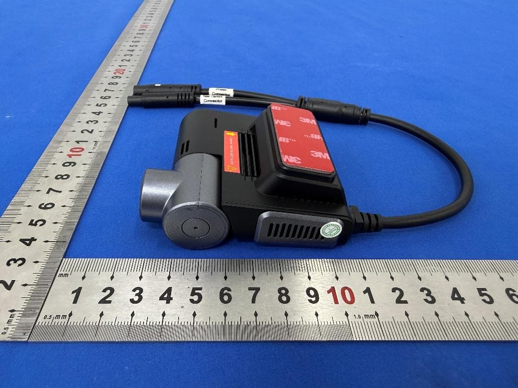
XUJG5201
Jun 26, 2026Car Sense Vision
Equipment Class
PCB - PCS Licensed Transmitter
XUJOADDPD1005A
Jun 05, 2026Automotive Diagnostic Tool
Equipment Class
NII - Unlicensed National Information Infrastructure TXXUJTSEN5S
Jan 27, 2026Programmable Universal RF Tire Pressure Sensor
Equipment Class
DSC - Part 15 Security/Remote Control Transmitter