XUJDBSCARTDBScar II
Launch Tech Co., Ltd.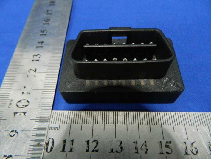
Click to zoom
Application Details
- Equipment Class
- DSS - Part 15 Spread Spectrum Transmitter
- Date of Grant
- Jul 24, 2013
- Application Purpose
- Original Equipment
- Date of Application
- Jul 24, 2013
- Equipment Note
- DBScar II
- Frequency Range
- 2402.00000000 - 2480.00000000
- Company
- Launch Tech Co., Ltd.
- Country
- China
Documents & Files
Document Text
Text extracted from the exhibit documents filed with the FCC. Open a document above to read the original.
Users Manual
- 2 -- 1 --3 -- 4 -- 5 -- 6 -- 7 -- 8 - LAUNCHLAUNCHLAUNCHLAUNCHLAUNCHLAUNCHLAUNCHLAUNCH DBScar II User's Manual LAUNCH TECH. CO., LTD. Launch Industrial Park, North of Wuhe Avenue, Banxuegang, Longgang, Shenzhen, Guangdong, P.R.China, 518129 Tel: +86-755-84528767 http://www.cnlaunch.com 1. Product Components 1.1. Ports & Indicators 1 2 Fig.1-1 Product illustration No.Name & Functions 1 O B D - 1 6 d i a g n o s t i c c o n n e c t o r : t o connect vehicle’s OBD2 diagnostic socket. 2 Power indicator(Red) and working indicator(Blue) 1.2. Accessories 3. Connected to vehicle 1) Locate vehicle’s DLC socket: it provides standard 16 pins and is generally located on driver’s side, under the dash. for the detail position, please refer to automobile repair manual. 2) Plug the DBScar II into DLC socket and the power indicator on DBScar II will light up about 3s. DBScar II x 1;• Quick start guide x 1• Upgrade tool installation CD x 1• Connector Extension Cable x 1• 2. Technical Specifications Working voltage: • 9~18V Working current(average): • 35mA Working temp: -20 to 65°C (-4 to 149 • o F) Storage temp: -40 to 85°C (-40 to 185 • o F) Storage humidity: <80%• Working humidity: <60%• Size(L*W*H): 53*30*24mm• be paired. Meanwhile, please make sure the communication distance between your phone and connector is kept within 2 meters to get better results. 6. Using DBScar II To perform this function, please confirm the following work has completed. 1) Bluetooth has been connected; 2) Connector has been connected to vehicle; 3) Mobile client software has been downloaded and installed. Fig. 3-1 4. Installing Software DBScar II APP is free to download. 1) Turn on your mobile smart device and link the network well; 2) Go into “App Store” (for iOS) or “Google Play” (for Android), search the key word “DBScar”, click DBScar II software client to download and install (for details, please refer to the corresponding user’s manual). 5. Bluetooth Setting Enter bluetooth setting interface, set bluetooth ON and scan for devices, the system will list out the search result. click the desired one to pair(the default name is DBS XXXXXXX, where XXXXXXX is the last 7 digits of product SN. NOTE: Before operating, bluetooth must FCC STATEMENT 1. This device complies with Part 15 of the FCC Rules. Operation is subject to the following two conditions: ( 1 ) T h i s d e v i c e m a y n o t c a u s e h a r m f u l interference. ( 2 ) Theis device must accept any interference received, including interference that may cause undesired operation. 2. Changes or modifications not expressly approved by the party responsible for compliance could void the user’s authority to operate the equipment. NOTE: This equipment has been tested and found to comply with the limits for a Class B digital device, pursuant to Part 15 of the FCC Rules. These limits are designed to provide reasonable protection against harmful interference in a residential installation. This equipment generates uses and can radiate radio frequency energy and, if not installed and used in accordance with the instructions, m a y c a u s e h a r m f u l i n t e r f e r e n c e t o r a d i o communications. However, there is no guarantee that interference will not occur in a particular installation. If this equipment does cause harmful interference to radio or television reception, which can be determined by turning the equipment off and on, the user is encouraged to try to correct the interference by one or more of the following measures: • Reorient or relocate the receivingantenna. • Increase the separation between theequipment and receiver. • Connect the equipment into an outlet on a circuit different from that to which the receiver is connected. • Consult the dealer or an experienced radio/TV technician for help. FCC Radiation Exposure Statement This equipment complies with FCC radiation exposure limits set forth for an uncontrolled environment. This equipment should be installed and operated with minimum distance 20cm between the radiator & your body.
Cover Letter(s)
SCS-F18: Project and Product Certification Representative Authorization Letter Page 1 of 2 Rev 3.0 775 Montague Expressway Milpitas, CA 95035 Tel: 408-526-1188 Fax: 408-526-1088 Email: [email protected] Project and Product Certification Representative Authorization Letter Revision History Reason for Amendment (current / obsolete) From To Approved Date Initial Release (obsolete) 1.0 1.0 Nov-14-2006 Revised wording (obsolete) 1.0 2.0 Sept–25-2007 Updated company template (current) 2.0 3.0 Jan-31-2012 SCS-F18: Project and Product Certification Representative Authorization Letter Page 2 of 2 Rev 3.0 Launch Tech Co., Ltd. 2013-7-22 To: SIEMIC, INC. 775 Montague Expressway, Milpitas, CA 95035 USA Dear Sir/Madam, Re: Project and Product Certification Representative Authorization Letter We, Launch Tech Co., Ltd. hereby authorize SIEMIC, INC. to act as a Certification Body for certifying for the following project(s): FCC ID: XUJDBSCART (DBScar II Model No.: DBScar II) We affirm that between SIEMIC and Launch Tech Co., Ltd., any difference in understanding, including test plan, measurement methods, applicable standards and relevant procedures and processes have been resolved prior to commencement of testing activities. Sincerely, Yibing Xue/Manager E-mail: [email protected] Phone: (86) 755-84528031 Fax: (86) 755-84528889 Address: Launch Industrial Park, North of Wuhe Rd., Banxuegang, Longgang, Shenzhen, China
Cover Letter(s)
Confidentiality Request Letter Launch Tech Co., Ltd. 2013-7-22 To: Federal Communications Commission Office of Engineering and Technology Equipment Authorization Division 7345 Oakland Mills Road Columbia, Maryland 21046 Subject: Permanent Confidentiality Request for FCC ID: XUJDBSCART We hereby request confidential treatment of information accompanying this application as outlined below: - Block diagram - Operation description - Schematic The above materials contain trade secrets and proprietary information not customarily released to the public. The public disclosure of these materials may be harmful to the applicant and provide unjustified benefits to its competitors. The applicant understands that pursuant to Section 0.457 & 0.459 of the Rules, disclosure of this application and all accompanying documentation will not be made before the date of the Grant for this application. Sincerely, Yibing Xue/Manager E-mail: [email protected] Phone: (86) 755-84528031 Fax: (86) 755-84528889 Address: Launch Industrial Park, North of Wuhe Rd., Banxuegang, Longgang, Shenzhen, China
ID Label/Location Info
Label Location Proposed Label Location on EUT
ID Label/Location Info
ID Label DBScar II FCC ID: XUJDBSCART Model Number: DBScar II Made in China This device complies with Part 15 of the FCC Rules. Operation is subject to the following two conditions: (1) this device may not cause harmful interference, and (2) this device must accept any interference received, including interference that may cause undesired operation.
Internal Photos
Bluetooth Module Antenna
RF Exposure Info
FCC ID : XUJDBSCART RF EXPOSURE EVALUATION According to FCC 1.1310: The criteria listed in the following table shall be used to evaluate the environment impact of human exposure to radio frequency(RF) Radiation as specified in §1.1307(b) Limits for Maximum Permissible Exposure(MPE) Frequency Range(MHz) Electric Field Strength(V/m) Magnetic Field Strength(A/m) Power Density(mW/cm 2 ) Average Time (A) Limits for Occupational/Control Exposures 300-1500 -- -- F/300 6 1500-100000 -- -- 5 6 (B) Limits for General Population/Uncontrol Exposures 300-1500 -- -- F/1500 6 1500-100000 -- -- 1 30 11.1 Friis transmission formula: Pd=(Pout*G)\(4*pi*R 2 ) Where Pd= Power density in mW/cm 2 Pout=output power to antenna in mW G= Numeric gain of the antenna relative to isotropic antenna Pi=3.1416 R= distance between observation point and center of the radiator in cm Pd the limit of MPE, 1mW/cm 2 . If we know the maximum gain of the antenna and total power input to the antenna, through the calculation, we will know the distance where the MPE limit is reached. 11.2 Measurement Result Power density limited: 1mW/ cm 2 Antenna gain: 0 dBi Max Output Peak power (dBm) Output Peak power (mW) Antenna Gain (dBi) Numeric Power density at 20cm (mW/ cm 2 ) Power density Limits (mW/cm 2 ) 3.73 2.36 1 0.0005 1
Test Report
TRF No:FCC 15.247/A Page 1 of 50 Report No: ES130704027E Shenzhen EMTEK Co.,Ltd. Building 69, Majialong Industry Zone, Nanshan District, Shenzhen,Guangdong,China www.emtek.com.cn Tel: +86-755-2695 4280 Fax: +86-755-2695 4282 Access to the World ELECTROMAGNETIC EMISSIONS COMPLIANCE REPORT INTENTIONAL RADIATOR CERTIFICATION TO FCC PART 15 SUBPARTC REQUIREMENT OF DBScar II MODEL No.: DBScar II FCC ID: XUJDBSCART Trademark: LAUNCH REPORT NO: ES130704027E ISSUE DATE: July 22, 2013 Prepared for Launch Tech Co., Ltd. Launch Industrial Park, North of Wuhe Rd., Banxuegang, Longgang, Shenzhen, China Prepared by SHENZHEN EMTEK CO., LTD Bldg 69, Majialong Industry Zone, Nanshan District, Shenzhen, Guangdong, China TEL: 86-755-26954280 FAX: 86-755-26954282 TRF No:FCC 15.247/A Page 2 of 50 Report No: ES130704027E Shenzhen EMTEK Co.,Ltd. Building 69, Majialong Industry Zone, Nanshan District, Shenzhen,Guangdong,China www.emtek.com.cn Tel: +86-755-2695 4280 Fax: +86-755-2695 4282 Access to the World VERIFICATION OF COMPLIANCE Applicant: Launch Tech Co., Ltd. Launch Industrial Park, North of Wuhe Rd., Banxuegang, Longgang, Shenzhen, China Manufacturer: Launch Tech Co., Ltd. Launch Industrial Park, North of Wuhe Rd., Banxuegang, Longgang, Shenzhen, China Product Description: DBScar II Model Number: DBScar II Serial Number: N/A File Number: ES130704027E We hereby certify that: The above equipment was tested by SHENZHEN EMTEK CO., LTD. The test data, data evaluation, test procedures, and equipment configurations shown in this report were made in accordance with the procedures given in ANSI C63.4 (2009) and the energy emitted by the sample EUT tested as described in this report is in compliance with conducted and radiated emission limits of FCC Rules Part 15.247. The test results of this report relate only to the tested sample identified in this report. Date of Test : July 4, 2013 to July 22, 2013 Prepared by : Joe Xia/Editor Reviewer : June Xie/Supervisor Approve & Authorized Signer : Lisa Wang/Manager TRF No:FCC 15.247/A Page 3 of 50 Report No: ES130704027E Shenzhen EMTEK Co.,Ltd. Building 69, Majialong Industry Zone, Nanshan District, Shenzhen,Guangdong,China www.emtek.com.cn Tel: +86-755-2695 4280 Fax: +86-755-2695 4282 Access to the World Ta b l e o f C o n t e n t s 1. GENERAL INFORMATION ................................................................................................. 5 1.1 PRODUCT DESCRIPTION........................................................................................................................... 5 1.2 RELATED SUBMITTAL(S) / GRANT (S) ..................................................................................................... 5 1.3 TEST METHODOLOGY.............................................................................................................................. 5 1.4 SPECIAL ACCESSORIES............................................................................................................................ 5 1.5 EQUIPMENT MODIFICATIONS.................................................................................................................. 5 1.6 TEST FACILITY........................................................................................................................................ 6 2. SYSTEM TEST CONFIGURATION .................................................................................... 7 2.1 EUT CONFIGURATION............................................................................................................................. 7 2.2 EUT EXERCISE........................................................................................................................................ 7 2.3 TEST PROCEDURE.................................................................................................................................... 7 2.4 LIMITATION............................................................................................................................................. 7 2.5 CONFIGURATION OF TESTED SYSTEM................................................................................................... 10 2.6 EQUIPMENT USED IN TESTED SYSTEM.................................................................................................. 10 2.7 DESCRIPTION OF TEST MODES............................................................................................................... 11 3. SUMMARY OF TEST RESULTS ....................................................................................... 12 4. CONDUCTED EMISSIONS TEST ..................................................................................... 13 4.1 MEASUREMENT PROCEDURE:................................................................................................................ 13 4.2 TEST SET-UP (BLOCK DIAGRAM OF CONFIGURATION) ....................................................................... 13 4.3 MEASUREMENT EQUIPMENT USED: ...................................................................................................... 13 4.4 CONDUCTED EMISSION LIMIT.................................................................................................................. 13 4.5 MEASUREMENT RESULT:....................................................................................................................... 13 5. RADIATED EMISSION TEST ............................................................................................ 14 5.1 MEASUREMENT PROCEDURE................................................................................................................. 14 5.2 TEST SET-UP (BLOCK DIAGRAM OF CONFIGURATION) ....................................................................... 15 5.3 MEASUREMENT EQUIPMENT USED: ...................................................................................................... 16 5.4 MEASUREMENT RESULT....................................................................…
Text truncated - open the document above for the full version.
Contact Information
Applicant
Ivy Zhong(Manager)
Test Firm
EMTEK (Shenzhen) Co., Ltd.David Lee
Technical Specifications
| # | Rule Parts | Frequency Range | Power Output |
|---|---|---|---|
| 1 | 15C | 2.40 GHz - 2.48 GHz | 2.40 mW |
Other Applications from Launch Tech Co., Ltd.
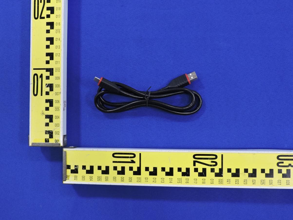
XUJOADDPD1303A
Sep 17, 2026Automotive Diagnostic Tool
Equipment Class
DTS - Digital Transmission System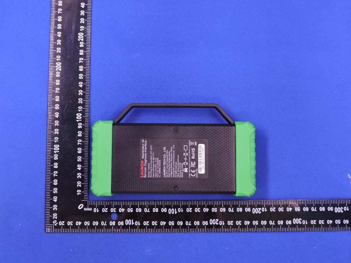
XUJS4006
Sep 04, 2026Remote Diagnosis Interface
Equipment Class
DTS - Digital Transmission SystemXUJEVT511S
Jul 09, 2026Battery Pack Airtightness Tester (High Voltage)
Equipment Class
DTS - Digital Transmission System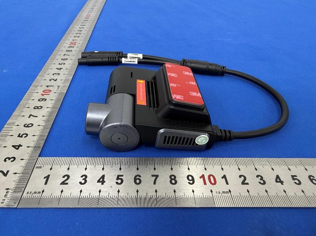
XUJG5201
Jun 26, 2026Car Sense Vision
Equipment Class
PCB - PCS Licensed Transmitter
XUJOADDPD1005A
Jun 05, 2026Automotive Diagnostic Tool
Equipment Class
NII - Unlicensed National Information Infrastructure TX