XUJDS402Automotive Diagnosis Terminal
Launch Tech Co., Ltd.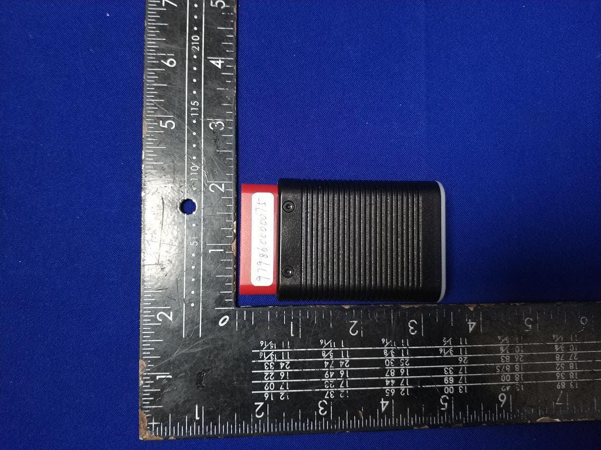
Click to zoom
Application Details
- Equipment Class
- DSS - Part 15 Spread Spectrum Transmitter
- Date of Grant
- Jun 16, 2020
- Application Purpose
- Original Equipment
- Date of Application
- Jun 16, 2020
- Equipment Note
- Automotive Diagnosis Terminal
- Frequency Range
- 2402.00000000 - 2480.00000000
- Company
- Launch Tech Co., Ltd.
- Country
- China
Documents & Files
Document Text
Text extracted from the exhibit documents filed with the FCC. Open a document above to read the original.
Users Manual
1. EasyDiag4 Introduction Internet Sends the collected vehicle data to the App via Bluetooth for analysis EasyDiag4 dongle Mobile terminal installed with THINKCAR App Wifi 3G/4G 2. Download EasyDiag4 App 3. Initial use 4. Start diagnostics 5. Maintenance & Reset 7. F&Q 8. Disclaimer 6. Precautions on Using EasyDiag4 There are 2 main components in the EasyDiag4 diagnostic system: EasyDiag4 dongle and EasyDiag4 App. The following illustration explains how the EasyDiag4 system works. The EasyDiag4 App for Android & iOS operating system is free to download. 1. Open Google Play (For Android) or App Store (For iOS). 2. Input the keyword "EasyDiag4" in the search bar. 3. Download and install it. After the installation is completed, a new icon “EasyDiag4” will appear on the home screen. 4.1 Preparation , 1. Turn on the vehicle ignition key. 2. Make sure the vehicle battery voltage range is 9~18V. 3. Vehicle connection: Plug the EasyDiag4 dongle into the vehicle’s DLC directly. The DLC)(Data Link Connector or Diagnostic Link Connector) is a typical standard 16-pin connector which links diagnostic code readers interface with the vehicle on-board computer. The DLC is usually located 12 inches from the center of the instrument panel (dash)under or around the driver’s side for most vehicles. The LED of the dongle illuminates solid red. 4. Bluetooth pairing: Go to "Settings", slide the Bluetooth switch to On, the system starts searching for all available Bluetooth devices. Tap the desired dongle from the result list to pair. The Bluetooth ID of the dongle is 97**********(where ********** stands for 10 digits). LED of the dongle illuminates solid BLUE. When pairing is successfully done, the dongle will be shown on the top of the "Paired devices" list and the 4.2 Start diagnostics AutoDetect and manual diagnosis are supported. If the AutoDetect fails, the system automatically switches to manual diagnosis mode. LED of the dongle illuminates BLUE and flashes. While communicating, the 3.1 App sign up 3.2 Free software download For initial use, you need to go through product registration. Follow the on-screen App prompts to complete it and login. The system automatically navigates to the Job Menu screen. Total 4 pieces of software are available for use free of charge. In which EOBD & DEMO can be downloaded directly, and 2 pieces of free vehicle diagnostic software are at your option and can be downloaded only after activating the EasyDiag 4 dongle. Activate EasyDiag4 Follow the steps below to proceed: 1). On the Job Menu screen, tap “+” to open the Software store. 2). Tap “Bind Now” on the bottom of the screen. 3). Input the Product S/N and Activation Code on the Confidential Paper, and tap “Activate” to bind it to the current user account. 4). Choose the desired software, and tap “Download” to download it. QUICK START GUIDE EOBD*DEMO* Free 2 vehicle software Mainly includes three function modules: EOBD, Full Modules Diagnostics and Reset. -- EOBD diagnosis and I/M readiness. -- Health checks for all vehicle systems. -- This feature makes it possible for users to perform different kinds of the reset operations. All reset software needs to subscribed separately. Moreover, user also can manage all the available software, which is sorted in alphabetic order at default. For subsequent use, the most frequently used software will stick on the top of the list. EOBD Diagnose Maintenance Here you can make an order for new diagnostic software or renew subscription of the expired diagnostic software. Manage activated dongles, saved diagnostic reports, personal profile, orders, update firmware and check software due date etc. 3.3 Job menu It mainly includes the following function modules: 3.4 Diagnostic software subscription To subscribe other diagnostic software, directly go to “Software store”. Input the desired software name in the search bar(wildcard search supported), and tap it from the search result to navigate to the subscription screen. Follow the on-screen instructions to finish the transaction. DLC Location Tap “Diagnose” Tap “Maintenance” Start decoding vehicle VIN Select the desired reset function Decoding OK Decoding failed Double check vehicle info. Select car brand Select vehicle make Scan all system modules Select service mode Select version Output health report Follow the instructions to proceed Select test system Select diagnostic function* Diagnostic Flowchart Reset Flowchart Manual Diagnosis Flowchart *Note: If you are fresh to vehicle diagnostics, you are recommended to use "DEMO" to get familiar with the diagnostic process. 1. This device is a precision electronic instrument. Handle it with care. Avoid dropping. 2. This device only operates on the 12V passenger vehicles equipped with OBD II management system. 3. Turn off the ignition switch while plugging / unplugging the device. 4. Be sure to always remove the device once testing and/or diagnosis is complete. Failure to do so may result in a drained or weakened battery. 1. LAUNCH owns full intellectual property rights of the hardware and software which used in this product. LAUNCH will deactivate the product and reserve the right to pursue its legal liability for any reverse engineering or cracking activities. 2. LAUNCH reserves the right to change product design and specifications. We try our best to keep the accuracy of the description, but LAUNCH does not bear any responsibilities caused by misunderstanding or info inaccuracy. 1. Communication error with vehicle ECU? Please check: 1. Whether the dongle is properly connected. 2. Whether the vehicle ignition switch is On. 3. If all checks are normal, send vehicle year, make, model and VIN number to us using Feedback feature. 2. Failed to enter into vehicle ECU system? Please confirm: 1. Whether the vehicle is equipped with the system. 2. Whether the tested system is electronic control system. 3. Whether the dongle is correctly connected. 4. Whether the vehicle ignition switch is On. 5. If…
Text truncated - open the document above for the full version.
Cover Letter(s)
Rev11/20/07 LaunchTechCo.,Ltd. FederalCommunicationsCommission AuthorizationandEvaluationDivision ConfidentialityRequestregardingapplicationforcertificationofFCCID:XUJDS402 PursuanttoSections0.457and0.459oftheCommission’sRules,weherebyrequestconfidential treatmentofinformationaccompanyingthisapplicationasoutlinedbelow: ExhibitTypeFileName BlockDiagram,blockdiagram.pdf SchematicsSCH.pdf OperationalDescriptionoperationdescription.pdf Theabovematerialscontaintradesecretsandproprietaryinformationnotcustomarilyreleasedto thepublic.Thepublicdisclosureofthesematerialsmaybeharmfultotheapplicantandprovide unjustifiedbenefitstoitscompetitors. TheapplicantunderstandsthatpursuanttoSection0.457oftheRules,disclosureofthis applicationandallaccompanyingdocumentationwillnotbemadebeforethedateoftheGrant forthisapplication. Sincerely, Name&TitleofAuthorizedSignature:YibingXue/Manager
Cover Letter(s)
M:\MasterDocuments\TEMPLATES\POA_Letter.doc LaunchTechCo.,Ltd. FederalCommunicationsCommission AuthorizationandEvaluationDivision 1435OaklandMillsRoad Columbia,MD21046 Date:2020-01-20 SUBJECT:FCCApplicationfor XUJDS402 ToWhomItMayConcern: We,theundersigned,herebyauthorizeLisaWang.atEMTEK(SHENZHEN)CO.,LTD /Bldg69,MajialongIndustryZone,NanshanDistrict,Shenzhen,Guangdong,Chinaonour behalf,toapplytotheFederalCommunicationsCommissiononourequipment.Anyand allactscarriedoutbyLisa.Wangonourbehalfshallhavethesameeffectasactsofour own. ThisistoadvisethatweareinfullcompliancewiththeAnti-DrugAbuseAct.We,the applicant,arenotsubjecttoadenialoffederalbenefitspursuanttoSection5301ofthe Anti-DrugActof1988,21USC853a,andnopartytotheapplicationissubjecttoadenial offederalbenefitspursuanttothatsection. Regards, Name&TitleofAuthorizedSignature:YibingXue/Manager
External Photos
EUTEXTERNALPHOTOGRAPHS 、 ----------------Theend----------------
ID Label/Location Info
labellocation
Internal Photos
EUTINTERNALPHOTOGRAPHS ----------------Theend----------------
RF Exposure Info
FCCID:XUJDS402 RFEXPOSUREEVALUATION AccordingtoFCC1.1310:Thecriterialistedinthefollowingtableshallbeusedto evaluatetheenvironmentimpactofhumanexposuretoradiofrequency(RF) Radiationasspecifiedin§1.1307(b) LimitsforMaximumPermissibleExposure(MPE) Frequency Range(MHz) ElectricField Strength(V/m) Magnetic Field Strength(A/m) Power Density(mW/cm 2 ) Average Time (A)LimitsforOccupational/ControlExposures 300-1500----F/3006 1500-100000----56 (B)LimitsforGeneralPopulation/UncontrolExposures 300-1500----F/15006 1500-100000----130 11.1Friistransmissionformula:Pd=(Pout*G)\(4*pi*R 2 ) Where Pd=PowerdensityinmW/cm 2 Pout=outputpowertoantennainmW G=Numericgainoftheantennarelativetoisotropicantenna Pi=3.1416 R=distancebetweenobservationpointandcenteroftheradiatorin20cm PdthelimitofMPE,1mW/cm 2 .Ifweknowthemaximumgainofthendtotal powerinputtotheantenna,throughthecalculation,wewillknowthedistance wheretheMPElimitisreached. 11.2MeasurementResult : Mode Max Measured power (dBm) Max tune-up power (dBm) Antenna gain Antenna Gain Numeric Evaluation result (mW/cm2) Powerdensity Limits (mW/cm2) BT1.53321.580.000631 BLE1.26321.580.000631
Test Report
ReportNo.ES200106038W01Page1of62Ver.1.0 TESTREPORT ProductName : AutomotiveDiagnosisTerminal ModelNumber : DS402 FCCID:XUJDS402 Preparedfor:LaunchTechCo.,Ltd. Address:LaunchIndustrialPark,NorthofWuheRoad,Banxuegang IndustrialZone,LonggangDistrict,ShenzhenCity, GuangdongProvince518129,P.R.China Preparedby:EMTEK(SHENZHEN)CO.,LTD. Address:Bldg69,MajialongIndustryZone,NanshanDistrict, Shenzhen,Guangdong,China Tel:(0755)26954280 Fax:(0755)26954282 ReportNumber:ES200106038W01 Date(s)ofTests:January06,2020toMay15,2020 Dateofissue:May27,2020 $二维码$ ReportNo.ES200106038W01Page2of62Ver.1.0 TableofContents 1TESTRESULTCERTIFICATION..............................................................................................................................................3 2EUTTECHNICALDESCRIPTION............................................................................................................................................5 3SUMMARYOFTESTRESULT.................................................................................................................................................6 4TESTMETHODOLOGY.............................................................................................................................................................7 4.1GENERALDESCRIPTIONOFAPPLIEDSTANDARDS.................................................................................................7 4.2MEASUREMENTEQUIPMENTUSED.............................................................................................................................7 4.3DESCRIPTIONOFTESTMODES......................................................................................................................................8 5FACILITIESANDACCREDITATIONS....................................................................................................................................9 5.1FACILITIES..........................................................................................................................................................................9 5.2LABORATORYACCREDITATIONSANDLISTINGS....................................................................................................9 6TESTSYSTEMUNCERTAINTY.............................................................................................................................................10 7SETUPOFEQUIPMENTUNDERTEST.................................................................................................................................11 7.1RADIOFREQUENCYTESTSETUP1.............................................................................................................................11 7.2RADIOFREQUENCYTESTSETUP2.............................................................................................................................11 7.3CONDUCTEDEMISSIONTESTSETUP.........................................................................................................................13 7.4SUPPORTEQUIPMENT....................................................................................................................................................13 8FREQUENCYHOPPINGSYSTEMREQUIREMENTS..........................................................................................................14 8.1STANDARDAPPLICABLE.......................................................................................................................................................14 8.2EUTPSEUDORANDOMFREQUENCYHOPPINGSEQUENCE...................................................................................................14 8.3EQUALHOPPINGFREQUENCYUSE......................................................................................................................................15 8.4FREQUENCYHOPPINGSYSTEM............................................................................................................................................15 9TESTREQUIREMENTS...........................................................................................................................................................16 9.120DBBANDWIDTH..........................................................................................................................................................16 9.2CARRIERFREQUENCYSEPARATION.........................................................................................................................22 9.3NUMBEROFHOPPINGFREQUENCIES........................................................................................................................28 9.4AVERAGETIMEOFOCCUPANCY(DWELLTIME)...................................................................................................30 9.5MAXIMUMPEAKCONDUCTEDOUTPUTPOWER....................................................................................................33 9.6CONDUCTEDSUPRIOUSEMISSION.............................................................................................................................39 9.7RADIATEDSPURIOUSEMISSION.................................................................................................................................46 9.8CONDUCTEDEMISSIONTEST......................................................................................................................................60 9.9ANTENNAAPPLICATION...............................................................................................................................................61 ReportNo.ES200106038W01Page3of62Ver.1.0 1TESTRESULTCERTIFICATION Applicant: LaunchTechCo.,Ltd. Address: LaunchIndustrialPark,NorthofWuheRoad,BanxuegangIndustrialZone, LonggangDistrict,ShenzhenCity,GuangdongProvince518129,P.R.China Manufacturer: LaunchTechCo.,Ltd. Address: LaunchIndustrialPark,NorthofWuheRoad,BanxuegangIndustrialZone, LonggangDistrict,ShenzhenCity,GuangdongProvince518129,P.R.China EUT:AutomotiveDiagnosisTerminal Model:DS402 Trademark:LAUNC…
Text truncated - open the document above for the full version.
Test Report
ReportNo.ES200106038W01Page36of62Ver.1.0 TestModel MaximumPeakConductedOutputPower Channel39:2441MHz π/4DQPSK TestModel MaximumPeakConductedOutputPower Channel78:2480MHz π/4DQPSK ReportNo.ES200106038W01Page37of62Ver.1.0 TestModel MaximumPeakConductedOutputPower Channel0:2402MHz8DPSK TestModel MaximumPeakConductedOutputPower Channel39:2441MHz8DPSK ReportNo.ES200106038W01Page38of62Ver.1.0 TestModel MaximumPeakConductedOutputPower Channel78:2480MHz8DPSK ReportNo.ES200106038W01Page39of62Ver.1.0 9.6CONDUCTEDSUPRIOUSEMISSION 9.6.1ApplicableStandard AccordingtoFCCPart15.247(d)andKDB558074D0115.247MEASGUIDANCEv05r02 9.6.2ConformanceLimit AccordingtoFCCPart15.247(d): Inany100kHzbandwidthoutsidethefrequencybandinwhichthespreadspectrumintentionalradiatorisoperating, theradiofrequencypowerthatisproducedbytheintentionalradiatorshallbeatleast20dBbelowthatinthe100 kHzbandwidthwithinthebandthatcontainsthehighestlevelofthedesiredpower,basedoneitheranRF conducted,providedthetransmitterdemonstratescompliancewiththepeakconductedpowerlimits. 9.6.3TestConfiguration Testaccordingtoclause7.1radiofrequencytestsetup1 9.6.4TestProcedure Thetransmitteroutput(antennaport)wasconnectedtothespectrumanalyzer Referencelevelmeasurement Establishareferencelevelbyusingthefollowingprocedure: SetinstrumentcenterfrequencytoDSSchannelcenterfrequency. SetSpan=approximately5timesthe20dBbandwidth,centeredonahoppingchannel. SettheRBW=100kHz.SettheVBW≥3xRBW. SetDetector=peak.SetSweeptime=autocouple. SetTracemode=maxhold.Allowtracetofullystabilize. UsethepeakmarkerfunctiontodeterminethemaximumMaximumconductedlevel. Notethatthechannelfoundtocontainthemaximumconductedlevelcanbeusedtoestablishthereferencelevel. Band-edgeComplianceofRFConductedEmissions Usethefollowingspectrumanalyzersettings: Span=wideenoughtocapturethepeakleveloftheemissionoperatingonthechannelclosesttotheband-edge,as wellasanymodulationproductswhichfalloutsideoftheauthorizedbandofoperation SetRBW 1%ofthespan=100kHzSetVBW RBW SetSweep=autoSetDetectorfunction=peakSetTrace=maxhold Allowthetracetostabilize.Setthemarkerontheemissionatthebandedge,oronthehighestmodulationproduct outsideoftheband,ifthislevelisgreaterthanthatatthebandedge.Enablethemarker-deltafunction,thenuse themarker-to-peakfunctiontomovethemarkertothepeakofthein-bandemission.Themarker-deltavaluenow displayedmustcomplywiththelimitspecifiedinthisSection. Now,usingthesameinstrumentsettings,enablethehoppingfunctionoftheEUT.Allowthetracetostabilize. Followthesameprocedurelistedabovetodetermineifanyspuriousemissionscausedbythehoppingfunctionalso complywiththespecifiedlimit. ConductedSpuriousRFConductedEmission Usethefollowingspectrumanalyzersettings: Span=wideenoughtocapturethepeaklevelofthein-bandemissionandallspuriousemissions(e.g.,harmonics) fromthelowestfrequencygeneratedintheEUTupthroughthe10thharmonic.(30MHzto25GHz).SetRBW= 100kHzSetVBW RBW SetSweep=autoSetDetectorfunction=peakSetTrace=maxhold Allowthetracetostabilize.Setthemarkeronthepeakofanyspuriousemissionrecorded.Theleveldisplayed mustcomplywiththelimitspecifiedinthisSection. ReportNo.ES200106038W01Page40of62Ver.1.0 9.6.5TestResults Bluetooth(GFSK,pi/4-DQPSK,8DPSK)modehavebeentested,andtheworstresult(GFSK)wasreportasbelow: TestModel MaximumConductedLevelRBW=100kHz Channel0:2402MHzGFSK TestModel ConductedSpuriousRFConductedEmission Channel0:2402MHzGFSK ReportNo.ES200106038W01Page41of62Ver.1.0 TestModel Band-edgeConductedEmissions Channel0:2402MHzGFSK TestModel MaximumConductedLevelRBW=100kHz Channel39:2441MHzGFSK ReportNo.ES200106038W01Page42of62Ver.1.0 TestModel ConductedSpuriousRFConductedEmission Channel39:2441MHzGFSK TestModel MaximumConductedLevelRBW=100kHz Channel78:2480MHzGFSK ReportNo.ES200106038W01Page43of62Ver.1.0 TestModel ConductedSpuriousRFConductedEmission Channel78:2480MHzGFSK TestModel Band-edgeConductedEmissions Channel78:2480MHzGFSK ReportNo.ES200106038W01Page44of62Ver.1.0 TestModel MaximumConductedLevelRBW=100kHz HoppingGFSK TestModel ConductedSpuriousRFConductedEmission HoppingGFSK ReportNo.ES200106038W01Page45of62Ver.1.0 TestModel Band-edgeConductedEmissions HoppingGFSK TestModel Band-edgeConductedEmissions HoppingGFSK ReportNo.ES200106038W01Page46of62Ver.1.0 9.7RADIATEDSPURIOUSEMISSION 9.7.1ApplicableStandard AccordingtoFCCPart15.247(d)and15.209andKDB558074D0115.247MEASGUIDANCEv05r02 9.7.2ConformanceLimit AccordingtoFCCPart15.247(d):radiatedemissionswhichfallintherestrictedbands,asdefinedin§15.205(a), mustalsocomplywiththeradiatedemissionlimitsspecifiedin§15.209(a)(see§15.205(c)). AccordingtoFCCPart15.205,Restrictedbands MHzMHzMHzGHz 0.090-0.11016.42-16.423399.9-4104.5-5.15 10.495-0.50516.69475-16.69525608-6145.35-5.46 2.1735-2.190516.80425-16.80475960-12407.25-7.75 4.125-4.12825.5-25.671300-14278.025-8.5 4.17725-4.1777537.5-38.251435-1626.59.0-9.2 4.20725-4.2077573-74.61645.5-1646.59.3-9.5 6.215-6.21874.8-75.21660-171010.6-12.7 6.26775-6.26825123-1382200-230014.47-14.5 8.291-8.294149.9-150.052310-239015.35-16.2 8.362-8.366156.52475-156.525252483.5-250017.7-21.4 8.37625-8.38675156.7-156.92690-290022.01-23.12 8.41425-8.41475162.0125-167.173260-326723.6-24.0 12.29-12.293167.72-173.23332-333931.2-31.8 12.51975-12.52025240-2853345.8-335836.43-36.5 12.57675-12.57725322-335.43600-4400(2) 13.36-13.41 AccordingtoFCCPart15.205,thelevelofanytransmitterspuriousemissioninRestrictedbandsshallnotexceed theleveloftheemissionspecifiedinthefollowingtable RestrictedFrequency(MHz)FieldStrength(μV/m)FieldStrength(dBμV/m)MeasurementDistance 0.009-0.4902400/F(KHz)20log(uV/m)300 0.490-1.70524000/F(KHz)20log(uV/m)30 1.705-303029.530 30-88100403 88-21615043.53 216-960200463 Above960500543 9.7.3TestConfiguration Testaccordingtoclause7.2radiofrequencytestsetup2 9.7.4TestProcedure ThistestisrequiredforanyspuriousemissionthatfallsinaRestrictedBand,asdefinedinSection15.205.Itmust beperformedwiththehighestgainofeachtypeofantennaproposedforusewiththeEUT.Usethefollowing spectrumanalyzersettings: ForAbove1GHz: TheEUTwasplacedonaturntablewhichis1.5mabovegro…
Text truncated - open the document above for the full version.
Test Setup Photos
TESTSETUPPHOTOGRAPHS 1.1.PhotosofRadiationEmissionMeasurement SpuriousEmissionTestSetup(Below1GHz) SpuriousEmissionTestSetup(Above1GHz) ----------------Theend----------------
Contact Information
Applicant
Ivy Zhong(Manager)
Test Firm
EMTEK (Shenzhen) Co., Ltd.Lisa Wang
[email protected]86 755 26954280
Technical Specifications
| # | Rule Parts | Frequency Range | Power Output |
|---|---|---|---|
| 1 | 15C | 2.40 GHz - 2.48 GHz | 1.40 mW |
Other Applications from Launch Tech Co., Ltd.
XUJOADDPD1303A
Sep 17, 2026Automotive Diagnostic Tool
Equipment Class
DTS - Digital Transmission System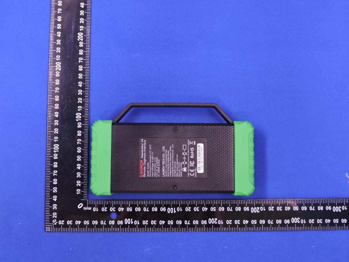
XUJS4006
Sep 04, 2026Remote Diagnosis Interface
Equipment Class
DTS - Digital Transmission SystemXUJEVT511S
Jul 09, 2026Battery Pack Airtightness Tester (High Voltage)
Equipment Class
DTS - Digital Transmission System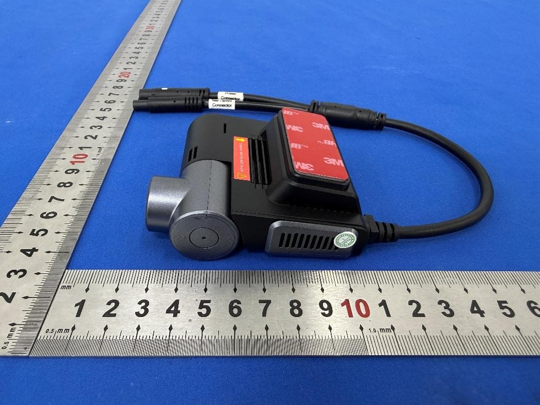
XUJG5201
Jun 26, 2026Car Sense Vision
Equipment Class
PCB - PCS Licensed Transmitter
XUJOADDPD1005A
Jun 05, 2026Automotive Diagnostic Tool
Equipment Class
NII - Unlicensed National Information Infrastructure TX