XUJHDIIIV2Heavy duty / Medium duty / Light duty Vehicle Communication Interface
Launch Tech Co., Ltd.
Click to zoom
Application Details
- Equipment Class
- DSS - Part 15 Spread Spectrum Transmitter
- Date of Grant
- Jan 18, 2020
- Application Purpose
- Original Equipment
- Date of Application
- Jan 18, 2020
- Equipment Note
- Heavy duty / Medium duty / Light duty Vehicle Communication Interface
- Frequency Range
- 2402.00000000 - 2480.00000000
- Company
- Launch Tech Co., Ltd.
- Country
- China
Documents & Files
Document Text
Text extracted from the exhibit documents filed with the FCC. Open a document above to read the original.
Users Manual
HD III Quick Start Guide 了解诊断盒 Knowledge of HD III Diagnostic socket (For connecting the diagnostic cable.) DC-IN power jack Displays the working status. t is defined as follows:I 1. Vehicle: While the HD III is communicating with the vehicle, the indicator lights up and flashes. Otherwise, it will not illuminate. 2. Power: It illuminates solid red when the is powered on. 3. Bluetooth: Blue indicates the is working in Bluetooth mode. 4. USB: It lights up when the is connected to the diagnostic tool via USB cable. 5. Wi-Fi: Blue indicates the is in wireless AP(access point) mode and works as a Wi-Fi hotspot. When the works in wireless client mode, it illuminates Blue & red. HD III HD III HD III HD III HD III LED Indicators The HD III works as a vehicle communication interface device, which is used read the vehicle data and then send it to the diagnostic tool via Bluetooth /Wi-Fi communication or USB connection. The LED indicators enable you to easily identify the working status of the .HD III Technical parameters: Working voltage: 9-36VDC Working temp.: -10°C-55°C Wi-Fi module: HLK-RM08K Frequency range: 2412-2472MHz Transmit power: 19.29dBm Bluetooth module: YG-218M-A2 Frequency range: 2402-2480MHz Transmit power: 16.62dBm Frequency ranges of Bluetooth and Wi-Fi can be used in Europe without restriction. Note: Before plugging/unplugging the diagnostic cable or adaptor cable, please turn the ignition off first. HD III (For collecting vehicle live data) To vehicle’s DLC Diagnostic cable Working Principle Accessory Checklist HD III Diagnostic cable USB cables Cigarette lighter Battery clamps cable Adaptor cable kit (For accessing vehicle live data) (To connect the and diagnostic tool to perform vehicle diagnosis.) HD III (To connect the to the diagnostic tool with different type of USB port.) HD III (A piece of paper bearing S/N and Activation Code, which is needed for your registration.) Power adaptor Password envelope (Sends the vehicle data to scan tool) (For connecting the power adaptor or cigarette lighter/battery clamps cable to obtain power. (For different vehicle diagnostic socket, it may be necessary to use one of the adaptor cables included within the kit.) (To supply power to the HD III through connection to vehicle’s battery.) (To supply power to the HD III through connection to cigarette lighter receptacle.) (To supply power to the HD III through AC outlet.) Scan tool (such as X-431 PAD II etc.) (For analyzing vehicle data and indicating the test results.) LAUNCH USB port (For connecting it to the diagnostic tool to perform vehicle diagnosis.) Bluetooth Wi-Fi Communication* USB cable * Note: For Wi-Fi communication setup, please refer to Section 2 for details. Vehicle Power Bluetooth USB WIFI 1. The DLC (Data Link Connector) is typically a connector where diagnostic code readers interface with the vehicle's on-board computer. 2. 3. 4. To perform vehicle diagnosis via USB cable, connect the B-shaped terminal of the USB cable to the HD III and other end to the USB port of the scan tool. Locate the vehicle’s DLC: The DLC location varies from vehicle to vehicle. It is generally located in driver’s cab. If no DLC is found, please refer to Automobile Repair Manual. Switch the ignition on. For vehicles equipped with OBD II management system, plug one end of the diagnostic cable into the vehicle’s DLC, and the other end into the diagnostic socket of the HD III, and then tighten the captive screws. For vehicles not equipped with OBD II management system, it is necessary to use the corresponding adaptor cable, and then follow one of the methods below to make connection: To establish the Wi-Fi communication between the HD III and scan tool, proceed the following steps: 2.Power the scan tool on and launch the application 3.After logging successfully, tap -> “Profile” -> “Connector communication manager” -> select “Use Wi-Fi communication”, a pull-down option list appears: Work as Wi-Fi hotspot: Once enabled, the and scan tool forms a LAN network to make communication. In this case, the scan tool can not surf the Internet. Work as network adaptor: Once enabled, a Wi-Fi connection dialog box appears. Input the Wi-Fi network name and access password until it is properly connected. In this case, the scan tool can surf the Internet and communicate with . 1. Follow the steps mentioned in Section 1 to make connection. . HD III HD III 1. Manufacturers shall ensure that radio equipment shall be so constructed that it can be operated in at least one Member State without infringing applicable requirements on the use of radio spectrum. 2. In cases of restrictions on putting into service or of requirements for authorisation of use, information available on the packaging shall allow the identification of the Member States or the geographical area within a Member State where restrictions on putting service or requirements for authorisation of use exist. Such information shall be completed in the restrictions accompanying the radio equipment. The Commission may adopt implementing acts specifying how to present that information. Those implementing acts shall be adopted in accordance with the advisory procedure referred to in Article 45(2). LAUNCH 1 2 Vehicle Connection Wi-Fi Communication Setup 4 HD IIIDiagnostic cable Cigarette lighter Battery clamps cable Adaptor cableTo vehicle's DLC To Cigarette lighter receptacle To vehicle battery Power adaptor To AC outlet A B C 3 Activate HD III & Download Software If you had a diagnostic tool of 12V passenger car configuration and intend to experience the diagnosis of commercial vehicles, follow the steps described below to activate the HD III: Note: Please make sure that the diagnostic tool is properly connected to the Internet before proceeding this step. 1. Launch the application, then tap -> “Profile”/ “My Data” -> “Activate Connector”. 2. Input the Product S/N and Activation Code, which can be obtained from the included Password Envelope…
Text truncated - open the document above for the full version.
Cover Letter(s)
Rev11/20/07 LaunchTechCo.,Ltd. FederalCommunicationsCommission AuthorizationandEvaluationDivision ConfidentialityRequestregardingapplicationforcertificationofFCCID:XUJHDIIIV2 PursuanttoSections0.457and0.459oftheCommission’sRules,weherebyrequestconfidential treatmentofinformationaccompanyingthisapplicationasoutlinedbelow: ExhibitTypeFileName BlockDiagram,blockdiagram.pdf SchematicsSCH.pdf OperationalDescriptionoperationdescription.pdf Theabovematerialscontaintradesecretsandproprietaryinformationnotcustomarilyreleasedto thepublic.Thepublicdisclosureofthesematerialsmaybeharmfultotheapplicantandprovide unjustifiedbenefitstoitscompetitors. TheapplicantunderstandsthatpursuanttoSection0.457oftheRules,disclosureofthis applicationandallaccompanyingdocumentationwillnotbemadebeforethedateoftheGrant forthisapplication. Sincerely, Name&TitleofAuthorizedSignature:YibingXue/Manager
Cover Letter(s)
M:\MasterDocuments\TEMPLATES\POA_Letter.doc LaunchTechCo.,Ltd. FederalCommunicationsCommission AuthorizationandEvaluationDivision 1435OaklandMillsRoad Columbia,MD21046 Date:2020-01-10 SUBJECT:FCCApplicationfor XUJHDIIIV2 ToWhomItMayConcern: We,theundersigned,herebyauthorizeLisaWang.atEMTEK(SHENZHEN)CO.,LTD /Bldg69,MajialongIndustryZone,NanshanDistrict,Shenzhen,Guangdong,Chinaonour behalf,toapplytotheFederalCommunicationsCommissiononourequipment.Anyand allactscarriedoutby_Lisa.Wangonourbehalfshallhavethesameeffectasactsofour own. ThisistoadvisethatweareinfullcompliancewiththeAnti-DrugAbuseAct.We,the applicant,arenotsubjecttoadenialoffederalbenefitspursuanttoSection5301ofthe Anti-DrugActof1988,21USC853a,andnopartytotheapplicationissubjecttoadenial offederalbenefitspursuanttothatsection. Regards, Name&TitleofAuthorizedSignature:YibingXue/Manager
External Photos
ExternalPhotos
Internal Photos
InternalPhotos Theend
Test Report
Report No. ES191217017W01 Page 1 of 64 Ver.1.0 TEST REPORT Product Name : Heavy duty / Medium duty / Light duty Vehicle Communication Interface Model Number : HD III FCC ID:XUJHDIIIV2 Prepared for: Launch Tech Co., Ltd. Address: Launch Industrial Park, North of Wuhe Road, Banxuegang Industrial Zone, Longgang District, Shenzhen City, Guangdong Province 518129, P.R. China Prepared by: EMTEK (SHENZHEN) CO., LTD. Address: Bldg 69, Majialong Industry Zone, Nanshan District, Shenzhen, Guangdong, China Tel: (0755) 26954280 Fax: (0755) 26954282 Report Number : ES191217017W01 Date(s) of Tests : December 17, 2019 to January 9, 2020 Date of issue: January 12, 2020 Report No. ES191217017W01 Page 2 of 64 Ver.1.0 Table of Contents 1 TEST RESULT CERTIFICATION..............................................................................................................................................3 2 EUT TECHNICAL DESCRIPTION............................................................................................................................................ 5 3 SUMMARY OF TEST RESULT................................................................................................................................................. 6 4 TEST METHODOLOGY.............................................................................................................................................................7 4.1 GENERAL DESCRIPTION OF APPLIED STANDARDS................................................................................................. 7 4.2 MEASUREMENT EQUIPMENT USED............................................................................................................................. 7 4.3 DESCRIPTION OF TEST MODES......................................................................................................................................8 5 FACILITIES AND ACCREDITATIONS....................................................................................................................................9 5.1 FACILITIES..........................................................................................................................................................................9 5.2 LABORATORY ACCREDITATIONS AND LISTINGS....................................................................................................9 6 TEST SYSTEM UNCERTAINTY.............................................................................................................................................10 7 SETUP OF EQUIPMENT UNDER TEST.................................................................................................................................11 7.1 RADIO FREQUENCY TEST SETUP 1.............................................................................................................................11 7.2 RADIO FREQUENCY TEST SETUP 2.............................................................................................................................11 7.3 CONDUCTED EMISSION TEST SETUP.........................................................................................................................13 7.4 SUPPORT EQUIPMENT....................................................................................................................................................13 8 FREQUENCY HOPPING SYSTEM REQUIREMENTS..........................................................................................................14 8.1 S TANDARDAPPLICABLE.......................................................................................................................................................14 8.2 EUT P SEUDORANDOMFREQUENCYHOPPINGSEQUENCE................................................................................................... 14 8.3 E QUALHOPPINGFREQUENCYUSE...................................................................................................................................... 15 8.4 F REQUENCYHOPPINGSYSTEM............................................................................................................................................ 15 9 TEST REQUIREMENTS........................................................................................................................................................... 16 9.1 20DB BANDWIDTH.......................................................................................................................................................... 16 9.2 CARRIER FREQUENCY SEPARATION......................................................................................................................... 22 9.3 NUMBER OF HOPPING FREQUENCIES........................................................................................................................28 9.4 AVERAGE TIME OF OCCUPANCY (DWELL TIME)................................................................................................... 30 9.5 MAXIMUM PEAK CONDUCTED OUTPUT POWER....................................................................................................33 9.6 CONDUCTED SUPRIOUS EMISSION.............................................................................................................................39 9.7 RADIATED SPURIOUS EMISSION.................................................................................................................................46 9.8 CONDUCTED EMISSION TEST...................................................................................................................................... 60 9.9 ANTENNA APPLICATION...............................................................................................................................................63 Report No. ES191217017W01 Page 3 of 64 Ver.1.0 1 TEST RESULT CERTIFICATION Applicant: Launch Tech Co., Ltd. Address: Launch Industrial Park, North of Wuhe Road, Banxuegang Industrial Zone, Longgang District, Shenzhen Cit…
Text truncated - open the document above for the full version.
Test Setup Photos
Setupphotos CONDUCTEDEMISSIONTEST RADIATEDEMISSIONTEST
Contact Information
Applicant
Ivy Zhong(Manager)
Test Firm
EMTEK (Shenzhen) Co., Ltd.Lisa Wang
[email protected]86 755 26954280
Technical Specifications
| # | Rule Parts | Frequency Range | Power Output |
|---|---|---|---|
| 1 | 15C | 2.40 GHz - 2.48 GHz | 1.60 mW |
Other Applications from Launch Tech Co., Ltd.
XUJOADDPD1303A
Sep 17, 2026Automotive Diagnostic Tool
Equipment Class
DTS - Digital Transmission System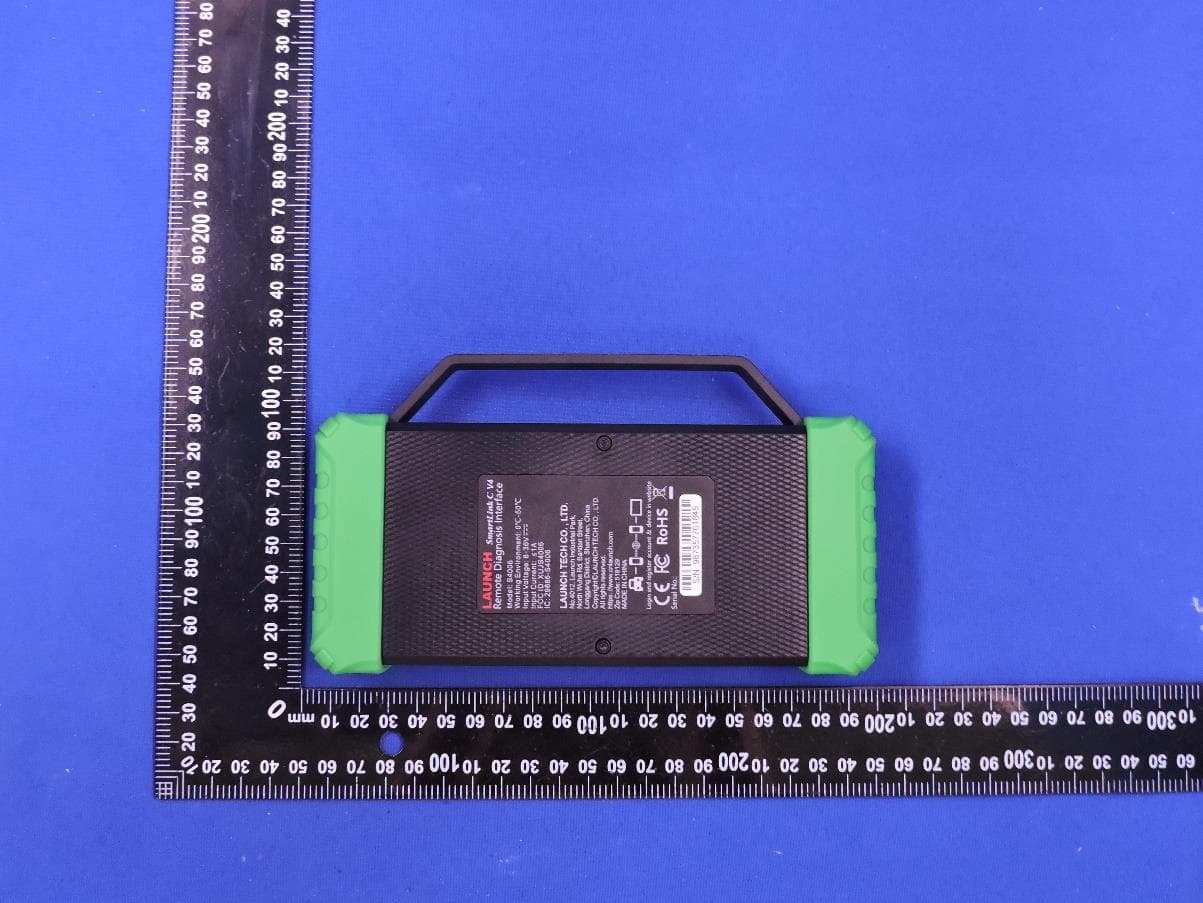
XUJS4006
Sep 04, 2026Remote Diagnosis Interface
Equipment Class
DTS - Digital Transmission SystemXUJEVT511S
Jul 09, 2026Battery Pack Airtightness Tester (High Voltage)
Equipment Class
DTS - Digital Transmission System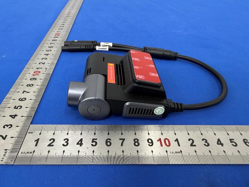
XUJG5201
Jun 26, 2026Car Sense Vision
Equipment Class
PCB - PCS Licensed Transmitter
XUJOADDPD1005A
Jun 05, 2026Automotive Diagnostic Tool
Equipment Class
NII - Unlicensed National Information Infrastructure TX