XUJLTR01RF-SENSOR
Launch Tech Co., Ltd.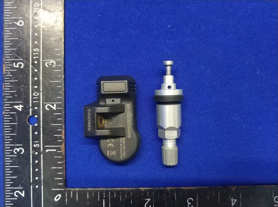
Click to zoom
Application Details
- Equipment Class
- DSC - Part 15 Security/Remote Control Transmitter
- Date of Grant
- Aug 06, 2020
- Application Purpose
- Original Equipment
- Date of Application
- Aug 06, 2020
- Equipment Note
- RF-SENSOR
- Frequency Range
- 433.92000000 - 433.92000000
- Company
- Launch Tech Co., Ltd.
- Country
- China
Documents & Files
Document Text
Text extracted from the exhibit documents filed with the FCC. Open a document above to read the original.
Users Manual
afety Instructions Any maintenance and repair work must be carried out by trained experts. Failure to do so may result in the failure of the TPMS sensor. LAUNCH does not assume any liability in case of faulty or incorrect installation of the unit. S CAUTION When mounting/dismounting the wheel, follow the operation guideline of wheel changer manufacturer strictly. Do not race with the vehicle on which the LTR-01 RF sensor is mounted, and always keep the drive speed under 240km/h. To guarantee optimal performance, the sensors may only be installed with original valves and accessories provided by LAUNCH. Make sure to program the sensors using LAUNCH-specific TPMS tool prior to installation. Do not install programmed TPMS sensors in damaged wheels. After installing the TPMS sensor, test the vehicle’s TPMS following the steps described in the original manufacturer’s user manual to confirm proper installation. RF-Sensor Quick Start Guide LTR-01 Metal Valve IMPORTANT: Read these instructions carefully and use this unit properly before operating. Failure to do so may cause damage and/or personal injury and will void the product warranty. www.x431.com LAUNCH +86-755-84557891 [email protected] FCC Warning Note: This equipment has been tested and found to comply with the limits for a Class B digital device, pursuant to part 15 of the FCC Rules. These limits are designed to provide reasonable protection against harmful interference in a residential installation. This equipment generates uses and can radiate radio frequency energy and, if not installed and used in accordance with the instructions, may cause harmful interference to radio communications. However, there is no guarantee that interference will not occur in a particular installation. If this equipment does cause harmful interference to radio or television reception, which can be determined by turning the equipment off and on, the user is encouraged to try to correct the interference by one or more of the following measures: - Reorient or relocate the receiving antenna. - Increase the separation between the equipment and receiver. - Connect the equipment into an outlet on a circuit different from that to which the receiver is connected. Any changes or modifications not expressly approved by the party responsible for compliance could void the user's authority to operate the equipment. - Consult the dealer or an experienced radio/TV technician for help. This device complies with part 15 of the FCC Rules. Operation is subject to the following two conditions: (1) This device may not cause harmful interference, and (2) this device must accept any interference received, including interference that may cause undesired operation. Warranty The sensor is guaranteed to be free from material and manufacturing defects for a period of twenty-four (24) months or for 31000 miles, whichever comes first. This warranty covers any defects in materials or workmanship under normal use during the warranty period. Excluded from the warranty are defects due to improper installation and usage, induction of defect by other products, damage due to collision or tire failure. 5. Remounting the tire Place the tire on the rim, ensure that the valve starts on the opposite side of the rim from the tire fitting head. Mount the tire over the rim. Caution: Strictly follow tire changer manufacturer’s instructions to mount the tire. Caution: Make sure that the nut and cap are installed on the outside of the rim. 3. Dismounting the sensor Remove the cap and nut from the valve stem, and then remove the sensor assembly from the wheel rim. 4. Mounting the sensor and valve Step 1. Remove the cap and nut from the valve stem. Step 2. Place the valve stem through the valve hole of the rim, ensuring the sensor body located on the inside of the rim. Assemble the nut back on the valve stem with a torque of 4N·m, then tighten the cap. T W C - 4 1 1 N I C Caution: The bead loosener must be facing the valve. Installation Steps Remove the valve cap and nut and deflate the tire. Use the bead loosener to break the tire bead. 1. Loosening the tire 2. Dismounting the tire Clamp the tire on the tire changer, and adjust the valve at 1 o’clock to the tire fitting head. Use the tire tool to dismount the tire bead. Caution: Always observe this starting point during the whole dismounting process. Sensor body Washer & nut Valve stem Rubber grommet and valve core assembly Screw Cap Technical Parameters Weight <30g Dimension(L*W*H) About 72*51*27mm Working Frequency 433MHz/315MHz Working Voltage 3V IP Rating IP67 Components Controls& When replacing or servicing the sensor, please only use the original valves and accessories provided by LAUNCH to ensure proper sealing. It is mandatory to replace the sensor if it is externally damage. Always remember to tighten the nut to the correct torque of 4N·m.
Cover Letter(s)
Launch Tech Co., Ltd. Federal Communications Commission Authorization and Evaluation Division Confidentiality Request regarding application for certification of FCC ID: XUJLTR01 Pursuant to Sections 0.457 and 0.459 of the Commission’s Rules, we hereby request confidential treatment of information accompanying this application as outlined below: Exhibit Type File Name Block Diagram, block diagram.pdf Schematics SCH.pdf Operational Description operation description.pdf The above materials contain trade secrets and proprietary information not customarily released to the public. The public disclosure of these materials may be harmful to the applicant and provide unjustified benefits to its competitors. The applicant understands that pursuant to Section 0.457 of the Rules, disclosure of this application and all accompanying documentation will not be made before the date of the Grant for this application. Sincerely, Name & Title of Authorized Signature: Yibing Xue/ Manager Rev 11/20/07
Cover Letter(s)
Launch Tech Co., Ltd. Federal Communications Commission Authorization and Evaluation Division 1435 Oakland Mills Road Columbia, MD 21046 Date: 2020-7-24 SUBJECT: FCC Application for FCC ID: XUJLTR01 To Whom It May Concern: We, the undersigned, hereby authorize Lisa Wang. at EMTEK (SHENZHEN) CO., LTD /Bldg 69, Majialong Industry Zone, Nanshan District,Shenzhen, Guangdong, China on our behalf, to apply to the Federal Communications Commission on our equipment. Any and all acts carried out by Lisa.Wang on our behalf shall have the same effect as acts of our own. This is to advise that we are in full compliance with the Anti- Drug Abuse Act. We, the applicant, are not subject to a denial of federal benefits pursuant to Section 5301 of the Anti-Drug Act of 1988, 21 USC853a, and no party to the application is subject to a denial of federal benefits pursuant to that section. Regards, Name & Title of Authorized Signature: Yibing Xue/ Manager \\Server\emc部\1.案件总档\2020年案件总档\Y\元征\ES200630095W 深圳市元征科技股份有限公司 RF-SENSOR 张贺南 FCC ID RF315Mhz\3 报告证 书\3 POA_Letter\POA_Letter.docx
External Photos
EUT EXTERNAL PHOTOGRAPHS EUT View 1 EUT View 2 TRF NO. FCC15/A Page 1 of 4 Report No.: ES200630095W Ver.1.0 EUT View 3 EUT View 4 TRF NO. FCC15/A Page 2 of 4 Report No.: ES200630095W Ver.1.0 EUT View 5 EUT View 6 TRF NO. FCC15/A Page 3 of 4 Report No.: ES200630095W Ver.1.0 EUT View 6 ----------------The end---------------- TRF NO. FCC15/A Page 4 of 4 Report No.: ES200630095W Ver.1.0
Internal Photos
EUT INTERNAL PHOTOGRAPHS EUT Housing and Board View 1: EUT Housing and Board View 2: TRF NO. FCC15/A Page 1 of 3 Report No.: ES200630095W Ver.1.0 EUT Housing and Board View 3: EUT Housing and Board View 4: 315/433.92MHz ANT. TRF NO. FCC15/A Page 2 of 3 Report No.: ES200630095W Ver.1.0 EUT Housing and Board View 5: EUT Housing and Board View 6: ----------------The end---------------- TRF NO. FCC15/A Page 3 of 3 Report No.: ES200630095W Ver.1.0
Test Report
TEST REPORT Product Name : RF-SENSOR Model Number : LTR-01 FCC ID : XUJLTR01 Prepared for : Launch Tech Co., Ltd. Address : Launch Industrial Park, North of Wuhe Road, Banxuegang Industrial Zone, Longgang District, Shenzhen City, Guangdong Province 518129, P.R. China Prepared by : EMTEK (SHENZHEN) CO., LTD. Address : Building 69, Majialong Industry Zone, Nanshan District, Shenzhen, Guangdong, China Tel: (0755) 26954280 Fax: (0755) 26954282 Report Number : ES200630095W02 Date(s) of Tests : Jul. 02, 2020 to Aug. 06, 2020 Date of issue : Aug. 06, 2020 Report No. ES200630095W02 Page 1 of 25 Ver.1.0 TEST RESULT CERTIFICATION Applicant : Launch Tech Co., Ltd. Address : Launch Industrial Park, North of Wuhe Road, Banxuegang Industrial Zone, Longgang District, Shenzhen City, Guangdong Province 518129, P.R. China Manufacturer : Launch Tech Co., Ltd. Address : Launch Industrial Park, North of Wuhe Road, Banxuegang Industrial Zone, Longgang District, Shenzhen City, Guangdong Province 518129, P.R. China EUT : RF-SENSOR Model Name : LT R-01 Trademark : LAUNCH Measurement Procedure Used: APPLICABLE STANDARDS STANDARD TEST RESULT FCC 47 CFR Part 2, Subpart J FCC 47 CFR Part 15, Subpart C PASS The above equipment was tested by SHENZHEN EMTEK CO., LTD. The test data, data evaluation, test procedures, and equipment configurations shown in this report were made in accordance with the procedures given in ANSI C63.10 (2013) and the energy emitted by the sample EUT tested as described in this report is in compliance with the requirements of FCC Rules Part 2 and Part 15.231 REQUIREMENTS. The test results of this report relate only to the tested sample identified in this report. Date of Test : Jul. 02, 2020 to Aug. 06, 2020 Prepared by : Qiang Wang /Editor Reviewer : Joe Xia/Editor Approve & Authorized Signer : Lisa Wang/Manager Report No. ES200630095W02 Page 2 of 25 Ver.1.0 Table of Contents 1 EUT TECHNICAL DESCRIPTION ..................................................................................... 4 2 SUMMARY OF TEST RESULT .......................................................................................... 5 3 TEST METHODOLOGY....................................................................................................... 6 3.1 GENERAL DESCRIPTION OF APPLIED STANDARDS .............................................................. 6 3.2 MEASUREMENT EQUIPMENT USED ........................................................................................... 6 3.3 DESCRIPTION OF TEST MODES .................................................................................................. 7 4 FACILITIES AND ACCREDITATIONS ............................................................................. 8 4.1 FACILITIES.......................................................................................................................................... 8 4.2 LABORATORY ACCREDITATIONS AND LISTINGS ................................................................... 8 5 TEST SYSTEM UNCERTAINTY ........................................................................................ 9 6 SETUP OF EQUIPMENT UNDER TEST ........................................................................ 10 6.1 RADIO FREQUENCY TEST SETUP 1 .......................................................................................... 10 6.2 RADIO FREQUENCY TEST SETUP 2 .......................................................................................... 10 6.3 CONDUCTED EMISSION TEST SETUP ...................................................................................... 12 6.4 BLOCK DIAGRAM CONFIGURATION OF TEST SYSTEM ....................................................... 13 6.5 SUPPORT EQUIPMENT ................................................................................................................. 13 7 TEST REQUIREMENTS .................................................................................................... 14 7.1 OCCUPIED BANDWIDTH ............................................................................................................... 14 7.2 FREQUENCY STABILITY ............................................................................................................... 16 7.3 RADIATED SPURIOUS EMISSION............................................................................................... 17 7.4 TRANSMISSION REQUIREMENT ................................................................................................ 22 7.5 CONDUCTED EMISSION TEST .................................................................................................... 24 7.6 ANTENNA APPLICATION ...................................................................................................................... 25 Report No. ES200630095W02 Page 3 of 25 Ver.1.0 1 EUT TECHNICAL DESCRIPTION Characteristics Description Product: RF-SENSOR Model Number: LT R-01 Modulation: FSK modulation Operating Frequency Range(s): 433.92MHz Number of Channels: 1 channel Max Transmit Power: 80.03 dBuV/m Antenna Type : Metal Antenna Antenna Gain: 0 dBi Power supply: DC 3V from button cell Adapter supply: N/A Temperature Range -10°C ~ 50°C Note: for more details, please refer to the User’s manual of the EUT. Report No. ES200630095W02 Page 4 of 25 Ver.1.0 2 SUMMARY OF TEST RESULT FCC Part Clause Test Parameter Verdict Remark 15.231(c) Occupied Bandwidth PA SS 15.231(d) Frequency stability N/A 15.231(e) Radiated Spurious Emissions PA SS 15.231(e) Transmission Requirement PA SS 15.203 Antenna Requirement PA SS 15.207(a) Conducted Emission N/A NOTE1: N/A (Not Applicable) RELATED SUBMITTAL(S) / GRANT(S): This submittal(s) (test report) is intended for FCC ID: XUJLTR01 filing to comply with Section 15.231 of the FCC Part 15, Subpart C Rules Report No. ES200630095W02 Page 5 of 25 Ver.1.0 3 TEST METHODOLOGY 3.1 GENERAL DESCRIPTION OF APPLIED STANDARDS According to its specifications, the EUT must comply with the requirements of th…
Text truncated - open the document above for the full version.
Test Setup Photos
TEST SETUP PHOTOGRAPHS 1.1. Photos of Radiation Emission Measurement Spurious Emission Test Setup (Below 1GHz) Spurious Emission Test Setup (Above 1GHz) ----------------The end----------------
Contact Information
Applicant
Ivy Zhong(Manager)
Test Firm
EMTEK (Shenzhen) Co., Ltd.Lisa Wang
[email protected]86 755 26954280
Technical Specifications
| # | Rule Parts | Frequency Range | Power Output |
|---|---|---|---|
| 2 | 15.231(e) | 433.92 MHz - 433.92 MHz | - |
Other Applications from Launch Tech Co., Ltd.
XUJOADDPD1303A
Sep 17, 2026Automotive Diagnostic Tool
Equipment Class
DTS - Digital Transmission System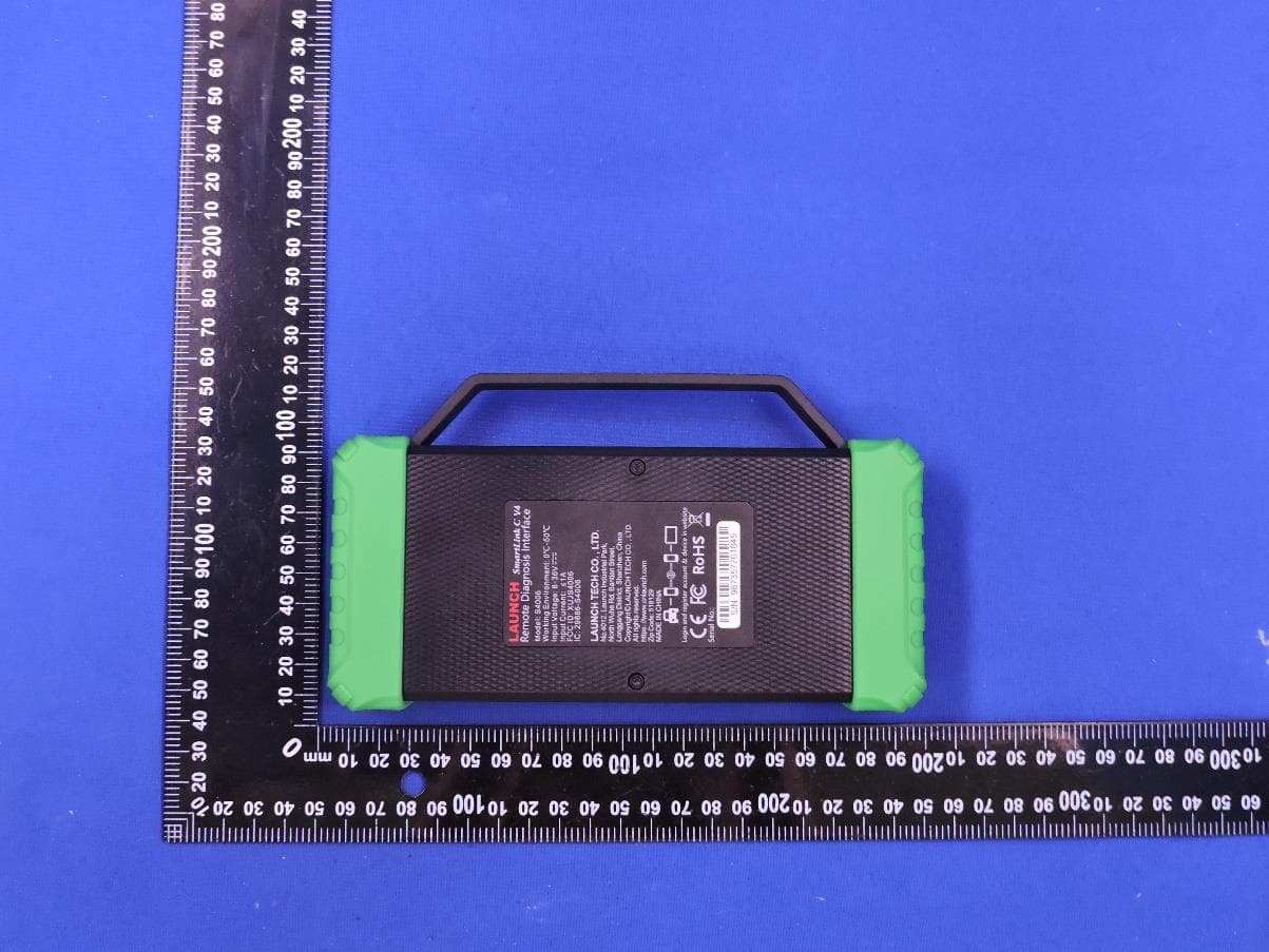
XUJS4006
Sep 04, 2026Remote Diagnosis Interface
Equipment Class
DTS - Digital Transmission SystemXUJEVT511S
Jul 09, 2026Battery Pack Airtightness Tester (High Voltage)
Equipment Class
DTS - Digital Transmission System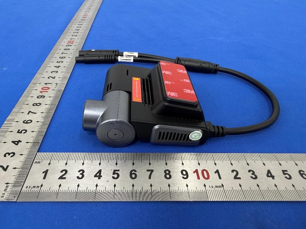
XUJG5201
Jun 26, 2026Car Sense Vision
Equipment Class
PCB - PCS Licensed Transmitter
XUJOADDPD1005A
Jun 05, 2026Automotive Diagnostic Tool
Equipment Class
NII - Unlicensed National Information Infrastructure TX