XUJM431PADAutomotive Diagnoais Computer
Launch Tech Co., Ltd.
Click to zoom
Application Details
- Equipment Class
- DTS - Digital Transmission System
- Date of Grant
- Jul 10, 2013
- Application Purpose
- Original Equipment
- Date of Application
- Jul 10, 2013
- Equipment Note
- Automotive Diagnoais Computer
- Frequency Range
- 2422.00000000 - 2452.00000000
- Company
- Launch Tech Co., Ltd.
- Country
- China
Documents & Files
Document Text
Text extracted from the exhibit documents filed with the FCC. Open a document above to read the original.
Users Manual
Version: V1.00.000 Revised date: 2013-01-16 I MAXIMUS User's Manual FCC INFORMATION This device complies with Part 15 of the FCC Rules. Operation is subject to the following two conditions: 1. This device may not cause harmful interference, and 2. This device must accept any interference received, including interference that may cause undesired operation. Note: This equipment has been tested and found to comply with the limits for a Class B digital device, pursuant to part 15 of the FCC Rules. These limits are designed to provide reasonable protection against harmful interference in a residential installation. This equipment generates, uses and can radiate radio frequency energy and, if not installed and used in accordance with the instructions, may cause harmful interference to radio communications. However, there is no guarantee that interference will not occur in a particular installation. If this equipment does cause harmful interference to radio or television reception, which can be determined by turning the equipment off and on, the user is encouraged to try to correct the interference by one or more of the following measures: — Reorient or relocate the receiving antenna. — Increase the separation between the equipment and receiver. — Connect the equipment into an outlet on a circuit different from that to which the receiver is connected. — Consult the dealer or an experienced radio/TV technician for help. Caution: Any changes or modifications not expressly approved by the party responsible for compliance could void the user’s authority to operate this equipment. RF Exposure: A distance of 20 cm shall be maintained between the antenna and users, and the transmitter module may not be co-located with any other transmitter or antenna. II MAXIMUS User's Manual All rights reserved! No part of this publication may be reproduced, stored in a retrieval system or transmitted, in any form or by any means of electronic, mechanical, photocopying and recording or otherwise, without the prior written permission of LAUNCH. This manual is designed only for the use of this unit. LAUNCH is not responsible for any use of this manual on the other units. The manual and all the samples herein can be changed without prior notice. Neither LAUNCH nor its affiliates shall be liable to the purchaser of this unit or third parties for damages, losses, costs or expenses incurred by purchaser or third parties as a result of: accident, misuse, or abuse of this unit, or unauthorized modifications, repairs, or alterations to this unit, or failure to strictly comply with LAUNCH operating and maintenance instructions. LAUNCH shall not be liable for any damages or problems arising from the use of any options or any consumable products other than those designated as Original LAUNCH Products or LAUNCH Approved Products by LAUNCH. Notice: other product names used herein are for identification purposes only and may be trademarks of their respective owners. LAUNCH disclaims any and all rights in those marks. This device is only for professional technicians and maintenance personnel. Registered Trademark LAUNCH is a registered trademark of LAUNCH TECH. CO., LTD. (LAUNCH) in China and other countries. In other countries where any of the LAUNCH trademarks, service marks, domain names, logos and company names is not registered, LAUNCH claims other rights associated with unregistered trademarks, service marks, domain names, logos and company names. Other products or company names referred to in this manual may be trademarks of their respective owners. You may not use any trademarks, service marks, domain names, logos or company name of LAUNCH or any third party without permission from the owner of the applicable trademarks, service marks, domain names, logos or company name. You may visit LAUNCH at http://www.dbscar.com for the information of Launch’s MAXIMUS and the other specialized diagnostic tools, or contact Launch by visiting http://www.cnlaunch.com or writing to Customer Center, LAUNCH TECH. CO., LTD., Launch Industrial Park, North of Wuhe Avenue, Banxuegang, Bantian, Longgang, Shenzhen, Guangdong. P.R. China, to request written permission to use materials on this manual for purposes or for all other questions relating to this manual. III MAXIMUS User's Manual Precautions on Operating Vehicle’s ECU Do not disconnect the vehicle inner consumer when the ignition switch is on. • High voltage transients may encounter at the moment of disconnecting, which may damage the sensors and the ECU. Protect the computer from magnetic object (such as wireless speaker) • Do cut off the power supply of ECU system before welding on the vehicle.• Pay more attention to the ECU and the sensors when the operation is next to • them. Ground yourself when you disassemble PROM, otherwise ECU and sensors • will be damaged by static electricity. Do not use the pointer ohmmeter instead of DMM to test the ECU and the • sensor without special requirement. Do not test electric devices in relation with ECU with a test lamp unless • otherwise expressly provided. Do wear a metal ground strip that one end around your wrist and the other to • the vehicle body when you get in and out the vehicle. Do connect ECU harness connector firmly, otherwise electro elements, such • as IC inside ECU, will be damaged. Precaution on Operation The appliance is a sophisticated electronic device, never have it clashed • when in use. Make sure the appliance is properly connected to the DLC to avoid • communication interruptions. During operation, keep the screen upward and leveled. Don’t disconnect the wired network or Wi-Fi network while software updating • or sending E-mail, otherwise, it will be interrupted. After the operation, the stylus shall be inserted into the hole on the back of • the main unit, and put away the cable and connector, etc accessories to the box to avoid the lost. Handle with care. Avoid collision. Unplug the power after operation.• IV MAXIMUS User's M…
Text truncated - open the document above for the full version.
Users Manual
FCC INFORMATION (additional) The highest measured body SAR value for this device is 0.837 W/Kg
Cover Letter(s)
Launch Tech Co., Ltd. Launch Industrial Park, North of Wuhe Rd., Banxuegang, Longgang, Shenzhen, China FCC Declaration of Conformity Number: CF302 Version: V03 Date: 22-08-2011 A declaration of conformity can only be issued by a U.S. entity based on a test report from an accredited laboratory. Accredited laboratories are located in the US, or in a country where the FCC has signed an MRA with. For a full list of accredited laboratories recognized by the FCC, please go to the FCC website https://fjallfoss.fcc.gov/oetcf/eas/reports/TestFirmSearch.cfm and for Test Firm Type, select “Accredited”. Additional information on administrative requirements for Declaration of Conformity can be found in KDB Publication Number 349827 . We, (responsible party must be a legal entity registered within the U.S., see FCC rule part 2.909 (2), must a U.S. address, such as importer or local manufacturer) Company Name: Launch Tech Co., Ltd. Address: Launch Industrial Park, North of Wuhe Rd., Banxuegang, Longgang, Shenzhen, China Postal/Zip: 518129 City: Shenzhen State/Province: Country: China Contact Person: Mr. Ms. Name: Yibing xue Function: Manager Email: [email protected] Web: Phone: +86-755- 84528031 Fax: +86-755- 84528889 declare for the equipment identified by: Product Description Automotive Diagnosis Computer Type or Model(s) Maximus Tradename or Brand(s) MATCO PAD that: (if the DoC test reports are available at this moment, please cross item a below) a). The following test reports, issued by an FCC accredited Laboratory, are subject to this declaration: Accredited Test Firm or Laboratory name: Test Report Number: Date of issue: Compliance Certification Services Inc.( Wugu Laboratory)T130429E06-D May 7, 2013 (if no DoC test report is available at this moment, then if you agree with the statement made in item b below, please cross item b below) b). DoC testing is pending at this moment, but will execute and finish the required DoC testing in an FCC accredited Laboratory before marketing the device in the U.S. The following Accredited Test Firm will complete DoC testing: Accredited Test Firm or Laboratory name: Attestation: In addition to our declaration above, we also will ensure to label the equipment with the FCC logo, the name of the manufacturer and model number, as required by the FCC rule part 15.19 . City and Country: Date: Name: (this must be a person) Function: Signature: (or official company stamp) Shenzhen China November 22, 2012 Yibing xue Manager This device complies with Part 15 of the FCC Rules. Operation is subject to the following two conditions: (1) this device may not cause harmful interference, and (2) this device must accept any interference received, including interference that may cause undesired operation. DoC
Cover Letter(s)
Launch Tech Co., Ltd. Launch Industrial Park, North of Wuhe Rd., Banxuegang, Longgang, Shenzhen, China FCC Confidentiality Request Number: CF303 Version: V02 Date:17-06-2011 To: Federal Communications Commission Equipment Authorization Branch 7435 Oakland Mills Road Columbia, MD 21046 Pursuant to 47 CFR Section 0.459(a) & (b), we, (the applicant / grantee) Company name Launch Tech Co., Ltd. Address Launch Industrial Park, North of Wuhe Rd., Banxuegang, Longgang, Shenzhen, China City Shenzhen Country China request for this certification filing under: Grantee Code Product Number FCC ID: XUJ M431PAD to maintain permanent confidentiality for the following documents submitted within this application: (please cross what is applicable, or add other documents, provide the file name and description) Exhibit File Name Description √ Operational Description √ Block Diagrams √ Schematics Diagrams Bill of Materials Above materials contain secrets, proprietary and technical information, which would customarily be guarded from competitors under 47 CFR, section 0.457(d)(2). Disclosure or publication or any portion of this company confidential material to other parties could cause substantial competitive harm and provide unjustified benefits for competitors. We understand that pursuant to 47 CFR section 0.457(d)(1)(ii) disclosure of the applicant and all accompanying documentation will not be made before the date of the grant. The documents indicated as confidential above, are not publicly available elsewhere. Attestation: City and Country: Date: Name: (this must be a person) Function: Signature: (or official company stamp) Shenzhen China October 29, 2012 Yibing xue Manager
Cover Letter(s)
Launch Tech Co., Ltd. Launch Industrial Park, North of Wuhe Rd., Banxuegang, Longgang, Shenzhen, China FCC Authorization Letter Number: CF304 Version: V03 Date: 01-08-2011 We, (the approval holder) Company name Launch Tech Co., Ltd. Address Launch Industrial Park, North of Wuhe Rd., Banxuegang, Longgang, Shenzhen, China City Shenzhen Country China declare that the following representative (agent): Name (person) Ruby Zhang Company name Supervisor Address Compliance Certification Services (Shenzhen) Inc. City No10-1, Mingkeda Logistics Park, No.18 Huanguan South RD. Guan lan Town, Baoan District, Shenzhen China Country Shenzhen China is hereby authorized to apply the following equipment for certification on our behalf: Product Description Automotive Diagnosis Computer Type or Model(s) Maximus Tradename or Brand(s) MATCO PAD We also authorize Teleconformity (Mr. M. Koop, Manager Certification, Address: Rietven 31, 7534NH Enschede, the Netherlands) to apply and sign this application for certification, registration or filing on our behalf (as representative agent or certifier). Attestation: City and Country: Date: Name: (this must be a person) Function: Signature: (or official company stamp) Shenzhen China November 22, 2012 Yibing xue Manager
External Photos
Report No: C130318Z01-RP1 Page 1 / 4 External Photos of EUT Report No: C130318Z01-RP1 Page 2 / 4 Report No: C130318Z01-RP1 Page 3 / 4 Report No: C130318Z01-RP1 Page 4 / 4
ID Label/Location Info
Label Location
ID Label/Location Info
Automotive Diagnosis Computer Model No: Maximus FCC ID: XUJM431PAD This device complies with Part 15 of the FCC Rules. Operation is subject to the following two conditions: 1. This device may not cause harmful interference, and 2. This device must accept any interference received, including interference that may cause undesired operation.
Internal Photos
Report No: C130318Z01-RP1 Page 1 / 17 Internal Photos of EUT Report No: C130318Z01-RP1 Page 2 / 17 Report No: C130318Z01-RP1 Page 3 / 17 Report No: C130318Z01-RP1 Page 4 / 17 Report No: C130318Z01-RP1 Page 5 / 17 Report No: C130318Z01-RP1 Page 6 / 17 Report No: C130318Z01-RP1 Page 7 / 17 Report No: C130318Z01-RP1 Page 8 / 17 Report No: C130318Z01-RP1 Page 9 / 17 Report No: C130318Z01-RP1 Page 10 / 17 Report No: C130318Z01-RP1 Page 11 / 17 BT Report No: C130318Z01-RP1 Page 12 / 17 Report No: C130318Z01-RP1 Page 13 / 17 WIFI Report No: C130318Z01-RP1 Page 14 / 17 Report No: C130318Z01-RP1 Page 15 / 17 Report No: C130318Z01-RP1 Page 16 / 17 Report No: C130318Z01-RP1 Page 17 / 17
RF Exposure Info
Compliance Certification Services Inc. Reference No .: C130617S01-SE Date of Issue: July 5, 2013 Report No .: C130617S01-SE Page 1 of 8 WIFI-Body-Rear Middle CH6............................................................................................................... 2 WIFI-Body-Right Middle CH6............................................................................................................. 3 WIFI-Body-Bottom Middle CH 6........................................................................................................ 5 Bluetooth-Body-Front Low CH00..................................................................................................... 6 Bluetooth-Body-Bottom Low CH00.................................................................................................. 8 Compliance Certification Services Inc. Reference No .: C130617S01-SE Date of Issue: July 5, 2013 Report No .: C130617S01-SE Page 2 of 8 Test Laboratory: Compliance Certification Services Inc. Date: 6/22/2013 WIFI-Body-Rear Middle CH6 DUT: Automotive Diagnosis Computer; Type: Maximus; Serial: N/A Communication System: IEEE 802.11b; Communication System Band: ISM 2.4GHz Band; Frequency: 2437 MHz;Duty Cycle: 1:1 Medium parameters used: f = 2437 MHz; σ = 1.925 S/m; ε r = 52.432; ρ = 1000 kg/m 3 Room Ambient Temperature: 23.4°C; Liquid Temperature: 22.0°C Phantom section: Flat Section Measurement Standard: DASY5 (IEEE/IEC/ANSI C63.19-2007) DASY Configuration: • Probe: EX3DV4 - SN3798; ConvF(6.92, 6.92, 6.92); Calibrated: 7/25/2012; • Sensor-Surface: 2mm (Mechanical Surface Detection) • Electronics: DAE4 Sn1245; Calibrated: 7/20/2012 • Phantom: ELI v4.0; Type: QDOVA001BB; Serial: 1102 • DASY52 52.8.4(1052); • SEMCAD X Version 14.6.8 (7028) WIFI/IEEE802.11b Body Rear Middle CH6/Area Scan (8x10x1): Measurement grid: dx=12mm, dy=12mm Maximum value of SAR (measured) = 0.344 W/kg WIFI/IEEE802.11b Body Rear Middle CH6/Zoom Scan (7x7x7)/Cube 0: Measurement grid: dx=5mm, dy=5mm, dz=5mm Reference Value = 0.488 V/m; Power Drift = 0.15 dB Peak SAR (extrapolated) = 0.506 W/kg SAR(1 g) = 0.273 W/kg; SAR(10 g) = 0.135 W/kg Maximum value of SAR (measured) = 0.391 W/kg Compliance Certification Services Inc. Reference No .: C130617S01-SE Date of Issue: July 5, 2013 Report No .: C130617S01-SE Page 3 of 8 Test Laboratory: Compliance Certification Services Inc. Date: 6/22/2013 WIFI-Body-Right Middle CH6 DUT: Automotive Diagnosis Computer; Type: Maximus; Serial: N/A Communication System: IEEE 802.11b; Communication System Band: ISM 2.4GHz Band; Frequency: 2437 MHz;Duty Cycle: 1:1 Medium parameters used: f = 2437 MHz; σ = 1.925 S/m; ε r = 52.432; ρ = 1000 kg/m 3 Room Ambient Temperature: 23.4°C; Liquid Temperature: 22.0°C Phantom section: Flat Section Measurement Standard: DASY5 (IEEE/IEC/ANSI C63.19-2007) DASY Configuration: • Probe: EX3DV4 - SN3798; ConvF(6.92, 6.92, 6.92); Calibrated: 7/25/2012; • Sensor-Surface: 2mm (Mechanical Surface Detection) • Electronics: DAE4 Sn1245; Calibrated: 7/20/2012 • Phantom: ELI v4.0; Type: QDOVA001BB; Serial: 1102 • DASY52 52.8.4(1052); • SEMCAD X Version 14.6.8 (7028) WIFI/IEEE802.11b Body Right Middle CH6/Area Scan (8x8x1): Measurement grid: dx=12mm, dy=12mm Maximum value of SAR (measured) = 0.521 W/kg WIFI/IEEE802.11b Body Right Middle CH6/Zoom Scan (7x7x7)/Cube 0: Measurement grid: dx=5mm, dy=5mm, dz=5mm Reference Value = 1.739 V/m; Power Drift = 0.20 dB Peak SAR (extrapolated) = 0.925 W/kg SAR(1 g) = 0.454 W/kg; SAR(10 g) = 0.212 W/kg Maximum value of SAR (measured) = 0.688 W/kg Compliance Certification Services Inc. Reference No .: C130617S01-SE Date of Issue: July 5, 2013 Report No .: C130617S01-SE Page 4 of 8 Compliance Certification Services Inc. Reference No .: C130617S01-SE Date of Issue: July 5, 2013 Report No .: C130617S01-SE Page 5 of 8 Test Laboratory: Compliance Certification Services Inc. Date: 6/22/2013 WIFI-Body-Bottom Middle CH 6 DUT: Automotive Diagnosis Computer; Type: Maximus; Serial: N/A Communication System: IEEE 802.11b; Communication System Band: ISM 2.4GHz Band; Frequency: 2437 MHz;Duty Cycle: 1:1 Medium parameters used: f = 2437 MHz; σ = 1.925 S/m; ε r = 52.432; ρ = 1000 kg/m 3 Room Ambient Temperature: 23.4°C; Liquid Temperature: 22.0°C Phantom section: Flat Section Measurement Standard: DASY5 (IEEE/IEC/ANSI C63.19-2007) DASY Configuration: • Probe: EX3DV4 - SN3798; ConvF(6.92, 6.92, 6.92); Calibrated: 7/25/2012; • Sensor-Surface: 2mm (Mechanical Surface Detection) • Electronics: DAE4 Sn1245; Calibrated: 7/20/2012 • Phantom: ELI v4.0; Type: QDOVA001BB; Serial: 1102 • DASY52 52.8.4(1052); • SEMCAD X Version 14.6.8 (7028) WIFI/IEEE802.11b Body Bottom Middle CH 6/Area Scan (10x9x1): Measurement grid: dx=12mm, dy=12mm Maximum value of SAR (measured) = 0.0285 W/kg WIFI/IEEE802.11b Body Bottom Middle CH 6/Zoom Scan (7x7x7)/Cube 0: Measurement grid: dx=5mm, dy=5mm, dz=5mm Reference Value = 1.214 V/m; Power Drift = 0.16 dB Peak SAR (extrapolated) = 0.0380 W/kg SAR(1 g) = 0.022 W/kg; SAR(10 g) = 0.013 W/kg Maximum value of SAR (measured) = 0.0299 W/kg Compliance Certification Services Inc. Reference No .: C130617S01-SE Date of Issue: July 5, 2013 Report No .: C130617S01-SE Page 6 of 8 Test Laboratory: Compliance Certification Services Inc. Date: 7/4/2013 Bluetooth-Body-Front Low CH00 DUT: Automotive Diagnosis Computer; Type: Maximus; Serial: N/A Communication System: Bluetooth; Communication System Band: ISM 2.4Ghz Band; Frequency: 2402 MHz;Duty Cycle: 1:1 Medium parameters used (extrapolated): f = 2402 MHz; σ = 1.959 S/m; ε r = 51.963; ρ = 1000 kg/m 3 Room Ambient Temperature: 23.4°C; Liquid Temperature: 22.0°C Phantom section: Flat Section Measurement Standard: DASY5 (IEEE/IEC/ANSI C63.19-2007) DASY Configuration: • Probe: EX3DV4 - SN3798; ConvF(6.92, 6.92, 6.92); Calibrated: 7/25/2012; • Sensor-Surface: 2mm (Mechanical Surface Detection) • Electronics: DAE4 Sn1245; Calibrated: 7/20/2012 • Phantom: ELI v4.0; Type: QDOVA001BB; Serial: 1102 • DASY52 52.8.5(1059)…
Text truncated - open the document above for the full version.
RF Exposure Info
Compliance Certification Services Inc. Report No: C130617S01-SF Date of Issue :July 5, 2013 FCC ID: XUJM431PAD Page 1 of 76 Rev. 01 This report shall not be reproduced except in full, without the written approval of Compliance Certification Services. ANSI/IEEE Std. C95.1-1992 In accordance with the requirements of FCC Report and Order: ET Docket 93-62, and OET Bulletin 65 Supplement C FCC SAR TEST REPORT For Product Name: Automotive Diagnosis Computer Brand Name: MATCO PAD Model No.: Maximus Series Model: N/A Test Report Number: C130617S01-SF Issued for Launch Tech Co.,Ltd. Launch Industrial Park,North of Wuhe Rd., Banxuegang,Longgang,Shenzhen,China Issued by Compliance Certification Services Inc. Kun shan Laboratory No.10 Weiye Rd., Innovation park, Eco&Tec, Development Zone, Kunshan City, Jiangsu, China TEL: 86-512-57355888 FAX: 86-512-57370818 Note: This report shall not be reproduced except in full, without the written approval of Compliance Certification Services Inc. This document may be altered or revised by Compliance Certification Services Inc. personnel only, and shall be noted in the revision section of the document. The client should not use it to claim product endorsement by A2LA or any government agencies. The test results in the report only apply to the tested sample. Compliance Certification Services Inc. Report No: C130617S01-SF Date of Issue :July 5, 2013 FCC ID: XUJM431PAD Page 2 of 76 Rev. 01 This report shall not be reproduced except in full, without the written approval of Compliance Certification Services. Revision History Revision REPORT NO. Date Page Revised Contents Original C130617S01-SF July 5, 2013 N/A N/A Compliance Certification Services Inc. Report No: C130617S01-SF Date of Issue :July 5, 2013 FCC ID: XUJM431PAD Page 3 of 76 Rev. 01 This report shall not be reproduced except in full, without the written approval of Compliance Certification Services. TABLE OF CONTENTS 1. CERTIFICATE OF COMPLIANCE (SAR EVALUATION) ........................................................... 4 2. EUT DESCRIPTION....................................................................................................................5 3. REQUIREMENTS FOR COMPLIANCE TESTING DEFINED BY THE FCC................................ 6 4. TEST METHODOLOGY.............................................................................................................. 6 5. DOSIMETRIC ASSESSMENT SETUP........................................................................................ 7 5.1 MEASUREMENT SYSTEM DIAGRAM ...........................................................................................................8 5.2 SYSTEM COMPONENTS...............................................................................................................................9 6. EVALUATION PROCEDURES ................................................................................................. 12 7. MEASUREMENT UNCERTAINTY............................................................................................ 17 8. EXPOSURE LIMIT .................................................................................................................... 18 9. EUT ARRANGEMENT .............................................................................................................. 19 9.1 ANTHROPOMORPHIC HEAD PHANTOM ...................................................................................................19 9.2 DEFINITION OF THE “CHEEK/TOUCH” POSITION ....................................................................................20 9.3 DEFINITION OF THE “TILTED” POSITION ..................................................................................................21 10. MEASUREMENT RESULTS..................................................................................................... 22 10.1 TEST LIQUIDS CONFIRMATION ...............................................................................................................22 10.2 LIQUID MEASUREMENT RESULTS ..........................................................................................................23 10.3 PROBE CALIBRATION PROCEDURE .......................................................................................................24 10.4 SYSTEM PERFORMANCE CHECK...........................................................................................................29 10.5 SAR TEST CONFIGURATIONS..................................................................................................................31 10.6 EUT TUNE-UP PROCEDURES AND TEST MODE....................................................................................33 10.7 EUT SETUP PHOTOS ................................................................................................................................35 10.8 SAR MEASUREMENT RESULTS...............................................................................................................36 10.9 SAR HANDSETS MULTI XMITER ASSESSMENT.....................................................................................37 11. EUT PHOTO ............................................................................................................................. 38 12. EQUIPMENT LIST & CALIBRATION STATUS........................................................................ 41 13. FACILITIES............................................................................................................................... 41 14. REFERENCES.......................................................................................................................... 41 15. ATTACHMENTS ....................................................................................................................... 41 Appendix A: Plots of Performance Check..................................................................................... 41 Appendix B: DASY Calibration Certificate .......................…
Text truncated - open the document above for the full version.
Test Report
Report No.: C130318Z01-RP1 FCC ID: XUJM431PAD Page 1 / 91 FCC 47 CFR PART 15 SUBPART C for Automotive Diagnosis Computer Model: Maximus Brand: MATCO PAD Test Report Number: C130318Z01-RP1 Issued Date:May 10, 2013 Issued for Launch Tech Co., Ltd. Launch Industrial Park, North of Wuhe Rd., Banxuegang, Longgang, Shenzhen, China Issued by: Compliance Certification Services (Shenzhen) Inc. No.10-1 Mingkeda Logistics park, No.18, Huanguan South Rd., Guan Lan Town, Baoan District, Shenzhen, China TEL: 86-755-28055000 FAX: 86-755-28055221 Note: This report shall not be reproduced except in full, without the written approval of Compliance Certification Services Inc. This document may be altered or revised by Compliance Certification Services Inc. personnel only, and shall be noted in the revision section of the document. The client should not use it to claim product endorsement by TAF, A2LA, NVLAP, NIST or any government agencies. The test results in the report only apply to the tested sample. Report No.: C130318Z01-RP1 FCC ID: XUJM431PAD Page 2 / 91 This report shall not be reproduced except in full, without the written approval of Compliance Certification Services. Revision History Rev. Issue No. Revisions Effect Page Revised By 00 C130318Z01-RP1 Initial Issue ALL Sunny Wang Report No.: C130318Z01-RP1 FCC ID: XUJM431PAD Page 3 / 91 This report shall not be reproduced except in full, without the written approval of Compliance Certification Services. TABLE OF CONTENTS 1 TEST CERTIFICATION.................................................................................................. 4 2 TEST RESULT SUMMARY............................................................................................ 5 3 EUT DESCRIPTION ....................................................................................................... 6 4 TEST METHODOLOGY ................................................................................................. 7 4.1. DESCRIPTION OF TEST MODES ...................................................................................... 7 5 SETUP OF EQUIPMENT UNDER TEST........................................................................ 8 5.1. DESCRIPTION OF SUPPORT UNITS................................................................................. 8 5.2. CONFIGURATION OF SYSTEM UNDER TEST ................................................................. 8 6 FACILITIES AND ACCREDITATIONS .......................................................................... 9 6.1. FACILITIES .......................................................................................................................... 9 6.2. ACCREDITATIONS ............................................................................................................. 9 6.3. MEASUREMENT UNCERTAINTY....................................................................................... 9 7 FCC PART 15.247 REQUIREMENTS.......................................................................... 10 7.1. POWER LINE CONDUCTED EMISSIONS MEASUREMENT........................................... 10 7.2. SPURIOUS EMISSIONS MEASUREMENT....................................................................... 14 7.3. 6dB BANDWIDTH MEASUREMENT ................................................................................. 50 7.4. PEAK OUTPUT POWER ................................................................................................... 58 7.5. BAND EDGES MEASUREMENT....................................................................................... 66 7.6. PEAK POWER SPECTRAL DENSITY MEASUREMENT.................................................. 84 Report No.: C130318Z01-RP1 FCC ID: XUJM431PAD Page 4 / 91 This report shall not be reproduced except in full, without the written approval of Compliance Certification Services. 1 TEST CERTIFICATION Product Automotive Diagnosis Computer Model Maximus Brand MATCO PAD Tested March 18~May 10, 2013 Applicant Launch Tech Co., Ltd. Launch Industrial Park, North of Wuhe Rd., Banxuegang, Longgang, Shenzhen, China Manufacturer Launch Tech Co., Ltd. Launch Industrial Park, North of Wuhe Rd., Banxuegang, Longgang, Shenzhen, China APPLICABLE STANDARDS StandardTest TypeStandardTest Type 15.207(a) Power Line Conducted Emissions 15.247(d) 15.209(a) � Spurious Emissions � Conducted Measurement � Radiated Emissions 15.247(a)(2) 6dB Bandwidth Measurement 15.247(b)(3) 15.247(b)(4) Peak Power Measurement 15.247(d) Band Edges Measurement 15.247(e) Peak Power Spectral Density We hereby certify that: The above equipment was tested by Compliance Certification Services Inc. The test data, data evaluation, test procedures, and equipment configurations shown in this report were made in accordance with the procedures given in ANSI C63.4: 2009 and the energy emitted by the sample EUT tested as described in this report is in compliance with the requirements of FCC Rules Part 15.207, 15.209, 15.247. The test res…
Text truncated - open the document above for the full version.
Contact Information
Applicant
Ivy Zhong(Manager)
Technical Contact
Test Firm
Compliance Certification Services (Shenzhen) Inc.Harry Li
Technical Specifications
| # | Rule Parts | Frequency Range | Power Output |
|---|---|---|---|
| 2 | 15C | 2.42 GHz - 2.45 GHz | 41.00 mW |
Other Applications from Launch Tech Co., Ltd.
XUJOADDPD1303A
Sep 17, 2026Automotive Diagnostic Tool
Equipment Class
DTS - Digital Transmission System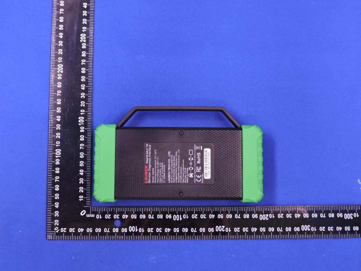
XUJS4006
Sep 04, 2026Remote Diagnosis Interface
Equipment Class
DTS - Digital Transmission SystemXUJEVT511S
Jul 09, 2026Battery Pack Airtightness Tester (High Voltage)
Equipment Class
DTS - Digital Transmission System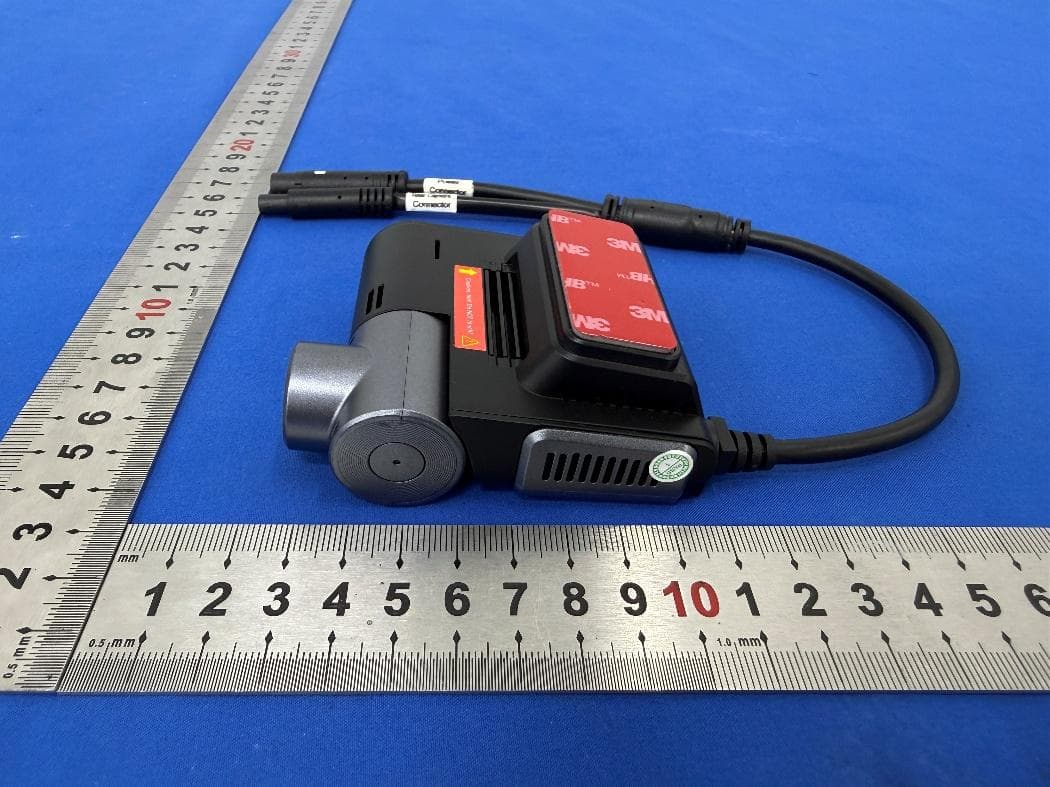
XUJG5201
Jun 26, 2026Car Sense Vision
Equipment Class
PCB - PCS Licensed Transmitter
XUJOADDPD1005A
Jun 05, 2026Automotive Diagnostic Tool
Equipment Class
NII - Unlicensed National Information Infrastructure TX