XUJMAX2Automotive Diagnosis Computer
Launch Tech Co., Ltd.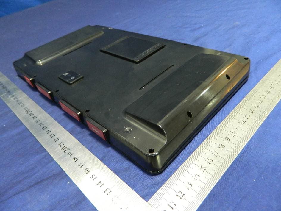
Click to zoom
Application Details
- Equipment Class
- DTS - Digital Transmission System
- Date of Grant
- May 07, 2014
- Application Purpose
- Original Equipment
- Date of Application
- May 06, 2014
- Equipment Note
- Automotive Diagnosis Computer
- Frequency Range
- 2422.00000000 - 2452.00000000
- Company
- Launch Tech Co., Ltd.
- Country
- China
Documents & Files
Document Text
Text extracted from the exhibit documents filed with the FCC. Open a document above to read the original.
Users Manual
Version: V1.00.000 Revised date: 02-10-2014 II MAXIMUS2.0 User's Manual Copyright Information Copyright © 2013 by LAUNCH TECH. CO., LTD. All rights reserved. No part of this publication may be reproduced, stored in a retrieval system, or transmitted in any form or by any means, electronic, mechanical, photocopying, recording or otherwise, without the prior written permission of LAUNCH. The information contained herein is designed only for the use of this unit. LAUNCH is not responsible for any use of this information as applied to other units. Neither LAUNCH nor its affiliates shall be liable to the purchaser of this unit or third parties for damages, losses, costs, or expenses incurred by purchaser or third parties as a result of: Accident, misuse, or abuse of this unit, or unauthorized modifi cations, repairs, or alterations to this unit, or failure to strictly comply with LAUNCH operating and maintenance instructions. LAUNCH shall not be liable for any damages or problems arising from the use of any options or any consumable products other than those designated as Original LAUNCH Products or LAUNCH Approved Products by LAUNCH. Trademark Information LAUNCH is a registered trademark of LAUNCH TECH CO., LTD. (also called LAUNCH for short) in China and other countries. All other LAUNCH trademarks, service marks, domain names, logos, and company names referred to in this manual are either trademarks, registered trademarks, service marks, domain names, logos, company names of or are otherwise the property of LAUNCH or its affiliates. In countries where any of the LAUNCH trademarks, service marks, domain names, logos and company names are not registered, LAUNCH claims other rights associated with unregistered trademarks, service marks, domain names, logos, and company names. Other products or company names referred to in this manual may be trademarks of their respective owners. You may not use any trademark, service mark, domain name, logo, or company name of LAUNCH or any third party without permission from the owner of the applicable trademark, service mark, domain name, logo, or company name. You may contact LAUNCH by visiting the website at www.cnlaunch.com, or writing to LAUNCH TECH. CO., LTD., Launch Industrial Park, North of Wuhe Avenue, Banxuegang, Bantian, Longgang, Shenzhen, Guangdong, P.R.China, to request written permission to use Materials on this manual for purposes or for all other questions relating to this manual. Safety Precautions Before using MAXIMUS2.0, please read the following safety information carefully. Never collide, throw, or punch MAXIMUS2.0, and avoid falling, • extruding and blending it. Do not use MAXIMUS2.0 in exceptionally cold or hot, dusty, damp • or dry environments. In places where MAXIMUS2.0 is forbidden or using MAXIMUS2.0 • may cause interference or generate a potential risk, please turn it off. To ensure a safe driving, please do not use MAXIMUS2.0 while • driving. Turn off MAXIMUS2.0 before boarding any airplane. • Do not dismantle MAXIMUS2.0 by yourself. If there is any inquiry, • please contact the dealer. Never place MAXIMUS2.0 into apparatus with strong • electromagnetic fi eld. Keep MAXIMUS2.0 far away from magnetic devices because its • radiations may erase the data stored on MAXIMUS2.0. Store MAXIMUS2.0 out of reach of children and do not allow • children to use it unsupervised. Please use the included battery and charger. Otherwise, explosion • may happen. Do not disconnect power abruptly when MAXIMUS2.0 is being • MAXIMUS2.0 User's Manual III formatted or in process of uploading or downloading. Or else it may result in program error. Precautions on Using MAXIMUS2.0 The ignition switch should be OFF while plugging or unplugging the • diagnostic connector. If your vehicle keeps unattended for a week or a long period, it • is suggested to unplug the connector from vehicle’s DLC to save battery power. While diagnosing a vehicle, you are not advised to use phone • or messaging, because it may cause a data communication interruption. If it happens, it is abnormal and just try to re-do it. Precautions on Operating Vehicle’s ECU Do not disconnect the vehicle inner consumer when the ignition • switch is on. High voltage transients may encounter at the moment of disconnecting, which may damage the sensors and the ECU. Protect the computer from magnetic object.• Do cut off the power supply of ECU system before welding on the • vehicle. Pay more attention to the ECU and the sensors when the operation • is next to them. Ground yourself when you disassemble PROM, otherwise ECU • and sensors will be damaged by static electricity. Do connect ECU harness connector firmly, otherwise electronic • elements, such as IC inside ECU, will be damaged. Table of Contents 1 Introduction ..................................................................................... 1 1.1 Product Profi le ............................................................................... 1 1.2 Features ........................................................................................ 1 1.3 Technical Specifi cations ................................................................ 1 2 Knowledge of MAXIMUS2.0 ........................................................... 2 2.1 MAXIMUS2.0 Display Tablet ......................................................... 3 2.2 MAXIMUS2.0 Docking Station....................................................... 4 2.3 Diagnostic Connector .................................................................... 5 2.4 MAXIMUS2.0 Accessory Checklist ................................................ 5 3 Preparations.................................................................................... 7 3.1 Charging MAXIMUS2.0 ................................................................. 7 3.2 On Using Your Battery ................................................................... 7 3.3 Power On / Power Off MAXIMUS2.0 .......................................…
Text truncated - open the document above for the full version.
Cover Letter(s)
SCS-F18: Project and Product Certification Representative Authorization Letter Page 1 of 2 Rev 3.0 775 Montague Expressway Milpitas, CA 95035 Tel: 408-526-1188 Fax: 408-526-1088 Email: [email protected] Project and Product Certification Representative Authorization Letter Reason for Amendment (current / obsolete) Revision History Approved Date From To Initial Release (obsolete) 1.0 1.0 Nov-14-2006 Revised wording (obsolete) 1.0 2.0 Sept–25-2007 Updated company template (current) 2.0 3.0 Jan-31-2012 SCS-F18: Project and Product Certification Representative Authorization Letter Page 2 of 2 Rev 3.0 LAUNCH TECH CO., LTD. 2014-04-18 To: SIEMIC, INC. 775 Montague Expressway, Milpitas, CA 95035 USA Dear Sir/Madam, Re: Project and Product Certification Representative Authorization Letter We, LAUNCH TECH CO., LTD. hereby authorize SIEMIC, INC. to act as a Certification Body for certifying for the following project(s): FCC ID: XUJMAX2 Automotive Diagnosis Computer; Model Number: Maximus 2.0 We affirm that between SIEMIC and LAUNCH TECH CO., LTD, any difference in understanding, including test plan, measurement methods, applicable standards and relevant procedures and processes have been resolved prior to commencement of testing activities. Sincerely, Signature YIBING.XUE / Manager E-mail: [email protected] Phone: (86) 755-84528031 Fax: (86) 755-84528889 Address Launch Industrial Park, North of Wuhe Rd., Banxuegang, Longgang, Shenzhen, China.
Cover Letter(s)
SCS-F19: Confidentiality Request Letter Page 1 of 2 Rev 3.0 775 Montague Expressway Milpitas, CA 95035 Tel: 408-526-1188 Fax: 408-526-1088 Email: [email protected] Confidentiality Request Letter Reason for Amendment (current / obsolete) Revision History Approved Date From To Initial Release (obsolete) 1.0 1.0 Nov-14-2006 Adding CFR 2.459 (obsolete) 1.0 2.0 August – 11 - 2008 Updated company template & Added text box (current) 2.0 3.0 Jan-31-2012 SCS-F19: Confidentiality Request Letter Page 2 of 2 Rev 3.0 LAUNCH TECH CO., LTD. 2014-04-18 To: Federal Communications Commission Authorization and Evaluation Division 7435 Oakland Mills Road Columbia, MD Subject: Permanent Confidentiality Request for FCC ID: XUJMAX2 We hereby request confidential treatment of information accompanying this application as outlined below: - Block Diagram - Schematics - Operational Description The above materials contain trade secrets and proprietary information not customarily released to the public. The public disclosure of these materials may be harmful to the applicant and provide unjustified benefits to its competitors. The applicant understands that pursuant to Section 0.457 & 0.459 of the Rules, disclosure of this application and all accompanying documentation will not be made before the date of the Grant for this application. Sincerely, Signature YIBING.XUE / Manager E-mail: [email protected] Phone: (86) 755-84528031 Fax: (86) 755-84528889 Address Launch Industrial Park, North of Wuhe Rd., Banxuegang, Longgang, Shenzhen, China.
Cover Letter(s)
LAUNCH TECH CO., LTD. Date: 2014-04-18 To: Federal Communications Commission 7435 Oakland Mills Road Columbia, MD FCC ID: XUJMAX2 To Whom It May Concern: This letter is to ascertain that LAUNCH TECH CO., LTD. Automotive Diagnosis Computer; Model Number: Maximus 2.0 has been the units used for conducting FCC compliance testing, the DoC part will be tested by FCC recognized test lab. If you have any question or concerns, pls. contact us. Sincerely, Signature YIBING.XUE / Manager E-mail: [email protected] Phone: (86) 755-84528031 Fax: (86) 755-84528889 Address Launch Industrial Park, North of Wuhe Rd., Banxuegang, Longgang, Shenzhen, China.
ID Label/Location Info
Automotive Diagnosis Computer Model No: Maximus 2.0 FCC ID: XUJMAX2 This device complies with Part 15 of the FCC Rules. Operation is subject to the following two conditions: 1. This device may not cause harmful interference, and 2. This device must accept any interference received, including interference that may cause undesired operation.
ID Label/Location Info
Label Location Proposed Label Location on EUT
Internal Photos
antenna WIFI& BT module
RF Exposure Info
TRF No.: FCC SAR/A Page 1 of 61 Report No.: ES140319181E Shenzhen EMTEK Co.,Ltd. Building 69, Majialong Industry Zone, Nanshan District, Shenzhen,Guangdong,China www.emtek.com.cn Tel: +86-755-2695 4280 Fax: +86-755-2695 4282 Access to the World SAR TEST REPORT OF Automotive Diagnosis Computer MODEL No.: Maximus 2.0 FCC ID: XUJMAX2 Trade Mark: MATCO TOOLS REPORT NO.: ES140319181E ISSUE DATE: April 18, 2014 Prepared for LAUNCH TECH CO., LTD. Launch Industrial Park, North of Wuhe Rd., Banxuegang, Longgang, Shenzhen, China. Prepared by SHENZHEN EMTEK CO., LTD Bldg 69, Majialong Industry Zone, Nanshan District, Shenzhen, Guangdong, China TEL: 86-755-26954280 FAX: 86-755-26954282 TRF No.: FCC SAR/A Page 2 of 61 Report No.: ES140319181E Shenzhen EMTEK Co.,Ltd. Building 69, Majialong Industry Zone, Nanshan District, Shenzhen,Guangdong,China www.emtek.com.cn Tel: +86-755-2695 4280 Fax: +86-755-2695 4282 Access to the World GENERAL SUMMARY Applicant: LAUNCH TECH CO., LTD. Launch Industrial Park, North of Wuhe Rd., Banxuegang, Longgang, Shenzhen, China. Product Description: Automotive Diagnosis Computer Model Number: Maximus 2.0 We hereby certify that: The above equipment was tested by SHENZHEN EMTEK CO., LTD. The test data, data evaluation, test procedures, and equipment configurations shown in this report were made in accordance with the following Reference standards: FCC 47CFR §2.1093 Radiofrequency Radiation Exposure Evaluation: Portable Devices ANSI C95.1, 1992: Safety Levels with Respect to Human Exposure to Radio Frequency Electromagnetic Fields, 3 kHz to 300 GHz.(IEEE Std C95.1-1991) IEEE Std 1528™-2003: IEEE Recommended Practice for Determining the Peak Spatial-Average Specific Absorption Rate (SAR) in the Human Head from Wireless Communications Devices: Measurement Techniques. KDB 865664 D01 SAR measurement 100 MHz to 6 GHz v01r02: SAR Measurement Requirements for 100 MHz to 6 GHz KDB 447498 D01 General RF Exposure Guidance v05r02: Mobile and Portable Device RF Exposure Procedures and Equipment Authorization Policies KDB 616217 D04 SAR for laptop and tablets v01r01: SAR Evaluation Considerations for Laptop, Notebook, Netbook and Tablet Computers KDB 248227 D01 SAR meas for 802 11 a b g v01r02: SAR Measurement Procedures for 802.11a/b/g Transmitters. This portable wireless equipment has been measured in all cases requested by the relevant standards. Test results in Chapter 4 of this test report are below limits specified in the relevant standards for the tested bands only. The test results of this report relate only to the tested sample identified in this report. Date of Test : March 20, 2014 to April 18, 2014 Prepared by : Jack Li/Editor Reviewer : June xie /Supervisor Approve & Authorized Signer : Lisa Wang/Manager TRF No.: FCC SAR/A Page 3 of 61 Report No.: ES140319181E Shenzhen EMTEK Co.,Ltd. Building 69, Majialong Industry Zone, Nanshan District, Shenzhen,Guangdong,China www.emtek.com.cn Tel: +86-755-2695 4280 Fax: +86-755-2695 4282 Access to the World Ta b l e o f C o n t e n t s 1. GENERAL INFORMATION................................................................................................... 4 1.1 P RODUCT DESCRIPTION......................................................................................................... 4 1.2 T HE MAXIMUM SAR10G VALUE........................................................................................... 5 1.3 S PECIAL ACCESSORIES.......................................................................................................... 5 1.4 T EST FACILITY...................................................................................................................... 5 2. SPECIFIC ABSORPTION RATE (SAR) ............................................................................... 6 2.1 I NTRODUCTION...................................................................................................................... 6 2.2 SAR DEFINITION................................................................................................................... 6 3. SAR MEASUREMENTS SYSTEM CONFIGURATION .................................................... 7 3.1 SAR MEASUREMENT SET-UP................................................................................................ 7 3.2 DASY5 E-FIELD PROBE SYSTEM.......................................................................................... 8 3.3 E- FIELD PROBE CALIBRATION............................................................................................... 9 3.4 O THER TEST EQUIPMENT...................................................................................................... 9 3.5 S CANNING PROCEDURE....................................................................................................... 13 3.6 D ATA STORAGE AND EVA L U AT I O N....................................................................................... 15 3.7 T ISSUE-EQUIVALENT LIQUID............................................................................................... 17 3.8 S YSTEM CHECK................................................................................................................... 17 4. MEASUREMENT PROCEDURES ...................................................................................... 19 4.1 G ENERAL DESCRIPTION OF TEST PROCEDURES................................................................... 19 4.2 M EASUREMENT VARIABILITY.............................................................................................. 19 4.3 T EST POSITION.................................................................................................................... 20 4.4 T EST RESULTS..................................................................................................................... 22 5. 700MHZ TO 3GHZ MEASUREMENT UNCERTAINTY ................................................. 25 6. MAIN TEST INSTRUMENTS ...........................................…
Text truncated - open the document above for the full version.
Test Report
TRF No.:FCC 15.247/A Page 1 of 49 Report No.: ES140319174E2 Shenzhen EMTEK Co.,Ltd. Building 69, Majialong Industry Zone, Nanshan District, Shenzhen,Guangdong,China www.emtek.com.cn Tel: +86-755-2695 4280 Fax: +86-755-2695 4282 Access to the World ELECTROMAGNETIC EMISSIONS COMPLIANCE REPORT INTENTIONAL RADIATOR CERTIFICATION TO FCC PART 15 SUBPART C REQUIREMENT OF Automotive Diagnosis Computer Model Name: Maximus 2.0 FCC ID: XUJMAX2 Trademark: MATCO TOOLS REPORT NO.: ES140319174E2 ISSUE DATE: April 18, 2014 Prepared for LAUNCH TECH CO., LTD. Launch Industrial Park, North of Wuhe Rd., Banxuegang, Longgang, Shenzhen, China. Prepared by SHENZHEN EMTEK CO., LTD. Bldg 69, Majialong Industry Zone, Nanshan District, Shenzhen, Guangdong, China TEL: 86-755-26954280 FAX: 86-755-26954282 TRF No.:FCC 15.247/A Page 2 of 49 Report No.: ES140319174E2 Shenzhen EMTEK Co.,Ltd. Building 69, Majialong Industry Zone, Nanshan District, Shenzhen,Guangdong,China www.emtek.com.cn Tel: +86-755-2695 4280 Fax: +86-755-2695 4282 Access to the World VERIFICATION OF COMPLIANCE Applicant: LAUNCH TECH CO., LTD. Launch Industrial Park, North of Wuhe Rd., Banxuegang, Longgang, Shenzhen, China. Manufacturer: LAUNCH TECH CO., LTD. Launch Industrial Park, North of Wuhe Rd., Banxuegang, Longgang, Shenzhen, China. Product Description: Automotive Diagnosis Computer Model Number: Maximus 2.0 File Number: ES140319174E2 Date of Test: March 20, 2014 to April 18, 2014 We hereby certify that: The above equipment was tested by SHENZHEN EMTEK CO., LTD. The test data, data evaluation, test procedures, and equipment configurations shown in this report were made in accordance with the procedures given in ANSI C63.4 (2009) and the energy emitted by the sample EUT tested as described in this report is in compliance with conducted and radiated emission limits of FCC Rules Part 15.247. The test results of this report relate only to the tested sample identified in this report. Date of Test : March 20, 2014 to April 18, 2014 Prepared by : Jack.Li/Editor Reviewer : June xie/Supervisor Approve & Authorized Signer : Lisa Wang/Manager TRF No.:FCC 15.247/A Page 3 of 49 Report No.: ES140319174E2 Shenzhen EMTEK Co.,Ltd. Building 69, Majialong Industry Zone, Nanshan District, Shenzhen,Guangdong,China www.emtek.com.cn Tel: +86-755-2695 4280 Fax: +86-755-2695 4282 Access to the World Ta b l e o f C o n t e n t s 1. GENERAL INFORMATION .............................................................................................................................. 5 1.1 PRODUCT DESCRIPTION .................................................................................................................................... 5 1.2 RELATED SUBMITTAL(S) / GRANT(S) ................................................................................................................. 5 1.3 TEST METHODOLOGY ....................................................................................................................................... 6 1.4 SPECIAL ACCESSORIES ...................................................................................................................................... 6 1.5 EQUIPMENT MODIFICATIONS ............................................................................................................................ 6 1.6 TEST FACILITY .................................................................................................................................................. 6 2. SYSTEM TEST CONFIGURATION ................................................................................................................. 7 2.1 EUT CONFIGURATION ....................................................................................................................................... 7 2.2 EUT EXERCISE ................................................................................................................................................. 7 2.3 TEST PROCEDURE ............................................................................................................................................. 7 2.4 CONFIGURATION OF TESTED SYSTEM ............................................................................................................... 7 3. DESCRIPTION OF TEST MODES ................................................................................................................... 9 4. SUMMARY OF TEST RESULTS ..................................................................................................................... 10 5. CONDUCTED EMISSIONS TEST .................................................................................................................. 11 5.1 MEASUREMENT PROCEDURE .......................................................................................................................... 11 5.2 TEST SET-UP (BLOCK DIAGRAM OF CONFIGURATION) .................................................................................. 11 5.3 MEASUREMENT EQUIPMENT USED ................................................................................................................. 11 5.4 CONDUCTED EMISSION LIMIT ......................................................................................................................... 11 5.5 MEASUREMENT RESULT .................................................................................................................................. 12 6. RADIATED EMISSION TEST ......................................................................................................................... 13 6.1 MEASUREMENT PROCEDURE .......................................................................................................................... 13 6.2 TEST SET-UP (BLOCK DIAGRAM OF CONFIGURATION) .................................................................................. 13 6.3 MEASUREMENT EQUIPMENT USED .....................................................................…
Text truncated - open the document above for the full version.
Test Setup Photos
PHOTOGRPHS OF TEST SETUP Radiated emission Conducted Emission
Contact Information
Applicant
Ivy Zhong(Manager)
Test Firm
EMTEK (Shenzhen) Co., Ltd.David Lee
Technical Specifications
| # | Rule Parts | Frequency Range | Power Output |
|---|---|---|---|
| 2 | 15C | 2.42 GHz - 2.45 GHz | 68.86 mW |
Other Applications from Launch Tech Co., Ltd.
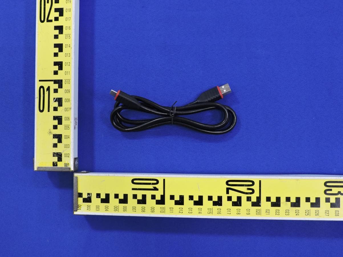
XUJOADDPD1303A
Sep 17, 2026Automotive Diagnostic Tool
Equipment Class
DTS - Digital Transmission System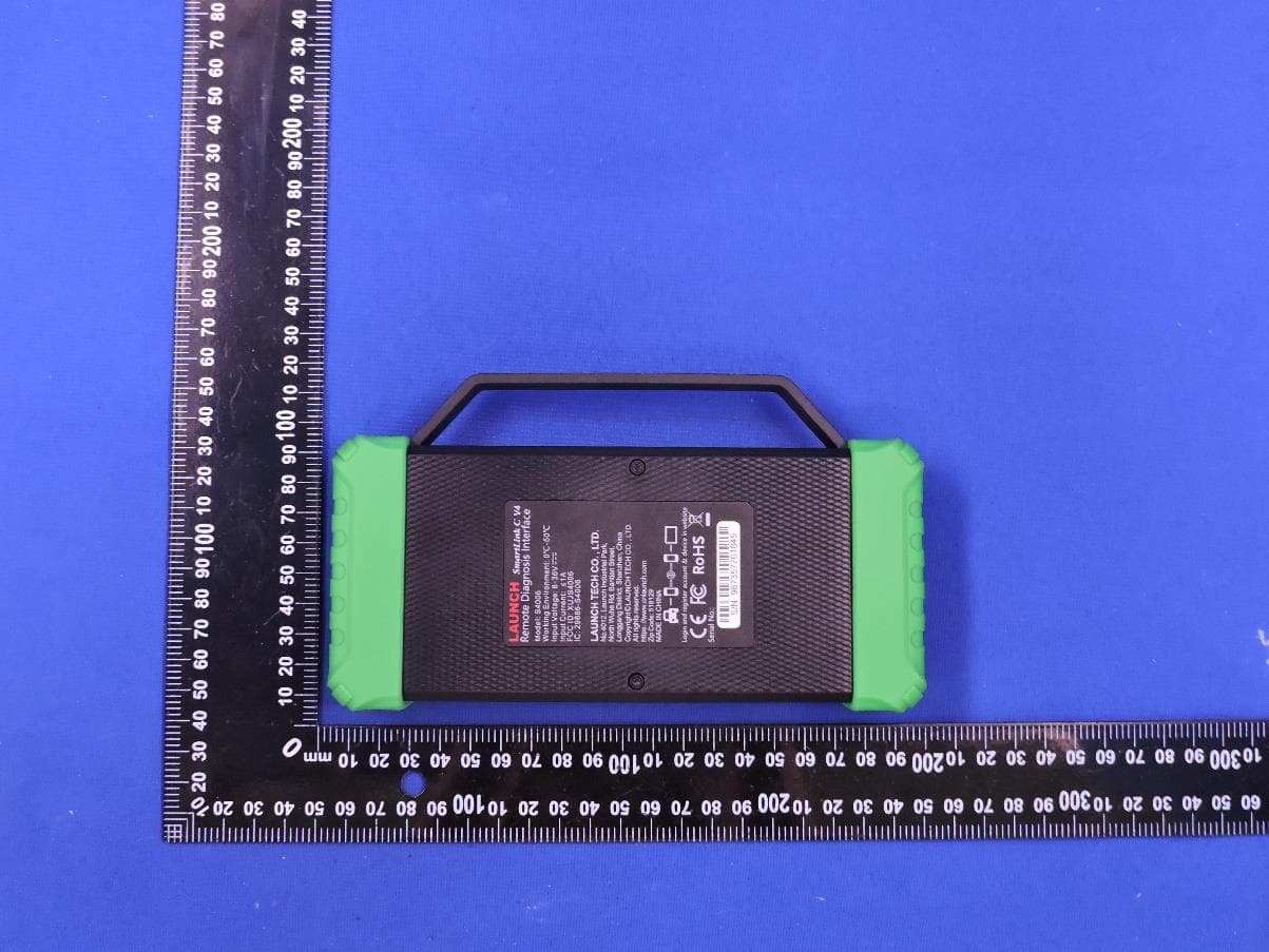
XUJS4006
Sep 04, 2026Remote Diagnosis Interface
Equipment Class
DTS - Digital Transmission SystemXUJEVT511S
Jul 09, 2026Battery Pack Airtightness Tester (High Voltage)
Equipment Class
DTS - Digital Transmission System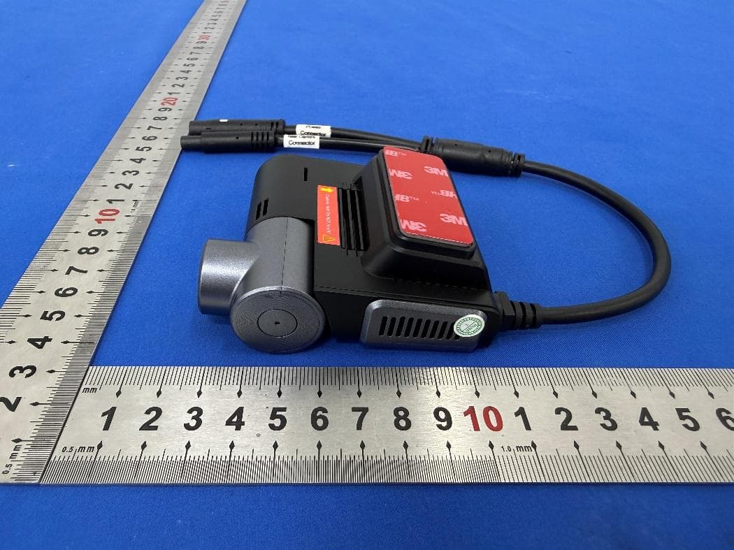
XUJG5201
Jun 26, 2026Car Sense Vision
Equipment Class
PCB - PCS Licensed Transmitter
XUJOADDPD1005A
Jun 05, 2026Automotive Diagnostic Tool
Equipment Class
NII - Unlicensed National Information Infrastructure TX