XUJRCUGIn vehicle data monitoring device
Launch Tech Co., Ltd.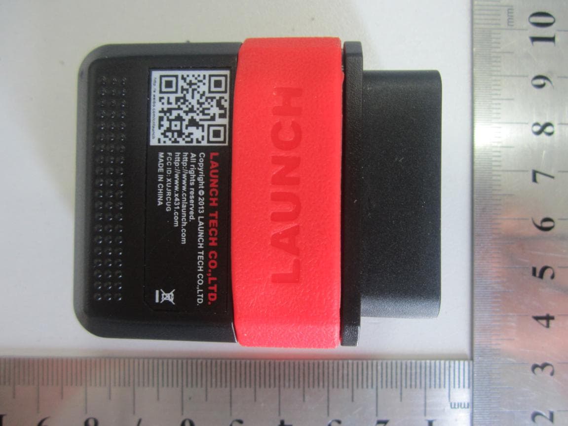
Click to zoom
Application Details
- Equipment Class
- JBP - Part 15 Class B Computing Device Peripheral
- Date of Grant
- Jul 14, 2013
- Application Purpose
- Original Equipment
- Date of Application
- Jul 14, 2013
- Equipment Note
- In vehicle data monitoring device
- Company
- Launch Tech Co., Ltd.
- Country
- China
Documents & Files
Document Text
Text extracted from the exhibit documents filed with the FCC. Open a document above to read the original.
Users Manual
RCU user’s manual (V1.00.000) (2013-05-19) All rights reserved! No part of this publication may be reproduced, stored in a retrieval system or transmitted, in any form or by any means of electronic, mechanical, photocopying and recording or otherwise, without the prior written permission of LAUNCH. This manual is designed only for the use of this unit. LAUNCH is not responsible for any use of this manual on the other units. The manual and all the samples herein can be changed without prior notice. Neither LAUNCH nor its affiliates shall be liable to the purchaser of this unit or third parties for damages, losses, costs or expenses incurred by purchaser or third parties as a result of: accident, misuse, or abuse of this unit, or unauthorized modifications, repairs, or alterations to this unit, or failure to strictly comply with LAUNCH operating and maintenance instructions. LAUNCH shall not be liable for any damages or problems arising from the use of any options or any consumable products other than those designated as Original LAUNCH Products or LAUNCH Approved Products by LAUNCH. Notice: other product names used herein are for identification purposes only and may be trademarks of their respective owners. LAUNCH disclaims any and all rights in those marks. This device is only for professional technicians and maintenance personnel. Precautions on operation The socket-outlet shall be installed near the equipment and shall be easily accessible. The instrument is a precision electronic instrument. Pay more attention when in use, do not have it dashed. Make sure that the connection between the device and DLC socket is secure and reliable when in use, GPRS transmission speed depends on mobile network, communication timeout failure would be occurred when network is busy (such as major festivals), and it also prone to happen in remote areas, Launch would not responsible for any consequences occurred by this failure. ODB program is pre-installed in the factory, please go into www.x431.com to download diagnostic software corresponding with your vehicle when initial use. SIM card is installed in the factory by our company, but we would not responsible for the recharge of the SIM card. CONTENT 1 Overview...........................................................................................................................................1 1.1 knowledge...................................................................................................................................1 1.2 Features.......................................................................................................................................1 1.3 Parameters...................................................................................................................................1 1.4 Accessories..................................................................................................................................1 1.5 Configuration...............................................................................................................................1 2 Introduction.....................................................................................................................................2 2.1 component...................................................................................................................................2 2.2 Structure......................................................................................................................................4 3. Connection and installation............................................................................................................4 3.1 PC tool and USB drive download and install..............................................................................4 3.2 Mobile client................................................................................................................................7 3.3 Connect to the vehicle.................................................................................................................7 4. How to use........................................................................................................................................9 4.1 working conditions......................................................................................................................9 1 Overview 1.1 knowledge Launch-developed RCU product is the first telematics product integrated GPS/GPRS/G-Sensor and other modules in the industry based on the system-wide data collection, after being connected with mobile terminal through running data to server that pushes SMS of vehicle real-time running data to users for understanding vehicle status, vehicle location, remote diagnosis, motorcade management..., It also features small size and simple installation. GPRS, it uploads vehicle 1.2 Features System-wide data collection。 GPRS/GSM communication,real-time data upload GPS/GPRS base station location Track playback G-sensor Statistics analysis Abnormal alarm Support local and remote upgrade 1.3 Parameters Working voltage:DC9-18V Working current:120mA(DC12V下) Standby current:<10mA Protection class:IP33 Working temperature:-20°C~70°C Storage temperature:-30°C~85°C Net weight:50g 1.4 Accessories Vehicle terminal Quick start guide Password envelope Connector extension cord 1.5 Configuration Function RCU-G GPS ☆ GPS assisted positioning ☆ Base station location ☆ GPRS/GSM ☆ Mobile phone terminal ☆ G-sensor ☆ 2G Communication ☆ GPS antenna internal 2 Introduction 2.1 component The product was composed by three parts: vehicle terminal (RCU), data server and client software. Fig2.1 Vehicle terminal(RCU) Connected with the vehicle’s diagnostic linking connector (DLC), with mainly function of data collection and upload (includes vehicle running data, location message, and so on) Data server Storage the data uploaded from the vehicle terminal and sent the orders to RCU and users …
Text truncated - open the document above for the full version.
External Photos
External Photos 1. EUT front view 2. EUT rear view 3. EUT left side view 4. EUT right side view 5. EUT top view 6. EUT bottom view
ID Label/Location Info
1.Label FCC Label & Location 2.Location
Internal Photos
Internal Photos 1. The EUT uncover view 2. Mainboard front view with shielding 3. Mainboard rear view with shielding 4. Mainboard front view without shielding 5. Mainboard rear view without shielding 6. GSM/GPRS chip view 7. CPU chip view 8. GSM/GPRS antenna view
Test Report
Report No.: SZ13050128E01 Page 2 of 13 TABLE OF CONTENTS 1. GENERAL INFORMATION .................................................................................................... 3 1.1 EUT Description ......................................................................................................................... 3 1.2 Test Standards and Results ........................................................................................................ 4 1.3 Facilities and Accreditations ...................................................................................................... 5 1.3.1 Facilities .................................................................................................................................... 5 1.3.2 Test Environment Conditions .................................................................................................... 5 1.3.3 Measurement Uncertainty ......................................................................................................... 5 2. TEST CONDITIONS SETTING............................................................................................... 6 2.1 Test Mode .................................................................................................................................... 6 2.2 Test Setup and Equipments List ................................................................................................ 7 2.2.1 Radiated Emission ..................................................................................................................... 7 3. 47 CFR PART 15B REQUIREMENTS .................................................................................. 10 3.1 Radiated Emission .................................................................................................................... 10 3.1.1 Requirement ............................................................................................................................ 10 3.1.2 Test Description ...................................................................................................................... 10 3.1.3 Frequency range of measurement ........................................................................................... 11 3.1.4 Test Result ............................................................................................................................... 11 Change History Issue Date Reason for change 1.0 July 4, 2013 First edition Report No.: SZ13050128E01 Page 3 of 13 1. GENERAL INFORMATION 1.1 EUT Description EUT Type .......................... RCU Serial No. .......................... (n.a., marked #1 by test site) Hardware Version ............. V1.00.002 Software Version ............... Applicant ........................... Manufacturer ..................... V1.00.001 Launch Tech Co., Ltd. Launch Industrial Park, North of Wuhe Rd., Banxuegang, Longgang, Shenzhen, China Launch Tech Co., Ltd. Launch Industrial Park, North of Wuhe Rd., Banxuegang, Longgang, Shenzhen, China Power supply .................... 12VDC Speed of the processor .. 120MHz (generated by the CPU) 32.768KHz (generated by the crystal oscillator) Note: 1. The EUT is a RCU which is the first telematics product integrated GPS/GPRS/3G/G-Sensor and other modules in the industry based on the system-wide data collection, it equipped with a Micro-USB port which can be connected to the PC for local upgrade and data upload. 2. For a more detailed description, please refer to Specification or User’s Manual supplied by the applicant and/or manufacturer. Report No.: SZ13050128E01 Page 4 of 13 1.2 Test Standards and Results The objective of the report is to perform testing according to 47 CFR Part 15 Subpart B: No. Identity Document Title 1 47 CFR Part 15 Radio Frequency Devices Test detailed items/section required by FCC rules and results are as below: No. Section Description Result 2 15.109 Radiated Emission PASS NOTE: The tests were performed according to the method of measurements prescribed in ANSI C63.4 2009. Report No.: SZ13050128E01 Page 5 of 13 1.3 Facilities and Accreditations 1.3.1 Facilities Shenzhen Morlab Communications Technology Co., Ltd. Morlab Laboratory is a testing organization accredited by China National Accreditation Service for Conformity Assessment (CNAS) according to ISO/IEC 17025. The accreditation certificate number is L3572. All measurement facilities used to collect the measurement data are located at FL.3, Building A, FeiYang Science Park, No.8 LongChang Road, Block 67, BaoAn District, ShenZhen, GuangDong Province, P. R. China 518101 . The test site is constructed in conformance with the requirements of ANSI C63.4(2009) and CISPR Publication 22(2010); the FCC registration number is 695796 . 1.3.2 Test Environment Conditions During the measurement, the environmental conditions were within the listed ranges: Temperature (°C): 15 - 35 Relative Humidity (%): 30 - 60 Atmospheric Pressure (kPa): 86 -106 1.3.3 Measurement Uncertainty The uncertainty is calculated using the methods suggested in the "Guide to the Expression of Uncertainty in Measurement" (GUM) published by ISO. Uncertainty of Radiated Emission: ±3.1dB Report No.: SZ13050128E01 Page 6 of 13 2. TEST CONDITIONS SETTING 2.1 Te s t M o d e The test mode (USB) The EUT configuration of the emission tests is EUT + DC Power Source + PC. During the measurement, the EUT was connected with a PC via the Micro-USB port, it was working normally, meanwhile, the EUT was powered by a DC Power Source . Report No.: SZ13050128E01 Page 7 of 13 2.2 Test Setup and Equipments List 2.2.1 Radiated Emission A. Test Setup: 1) For radiated emissions from 9kHz to 30MHz 2) For radiated emissions from 30MHz to1GHz Report No.: SZ13050128E01 Page 8 of 13 3) For radiated emissions above 1GHz The test is performed in a 3m Semi-Anechoic Chamber; the antenna factor, cable loss and so on of the site (factors) is calculated to correct the reading. The EUT is placed on a…
Text truncated - open the document above for the full version.
Test Setup Photos
Test Setup Photos 1. Conducted emission main’s port front view 2. Conducted emission main’s port side view 3. Radiated emission (9KHz-30MHz) 4. Radiated emission (30MHz-1GHz) 5. Radiated emission (above 1GHz)
Contact Information
Applicant
Ivy Zhong(Manager)
Technical Contact
Shenzhen Morlab Communications Technology Co.,LtdIvy Zhu
[email protected]86-755-36698618
FL.3, Building A, FeiYang Science Park, · ShenZhen, GuangDong Province · China
Test Firm
Shenzhen Morlab Communications Technology Co., LtdIvy zhu
Technical Specifications
| # | Rule Parts | Frequency Range | Power Output |
|---|---|---|---|
| 1 | 15B | - | - |
Other Applications from Launch Tech Co., Ltd.
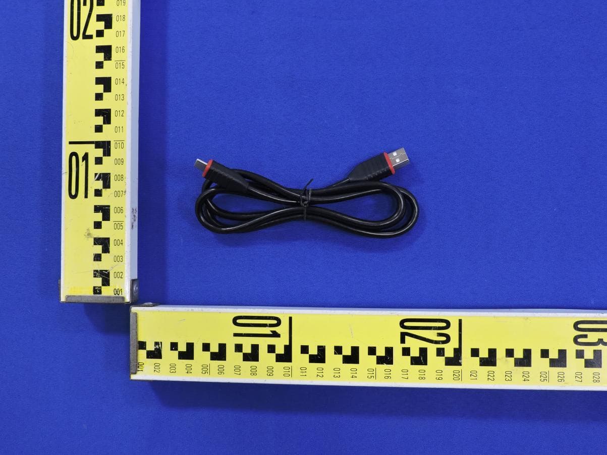
XUJOADDPD1303A
Sep 17, 2026Automotive Diagnostic Tool
Equipment Class
DTS - Digital Transmission System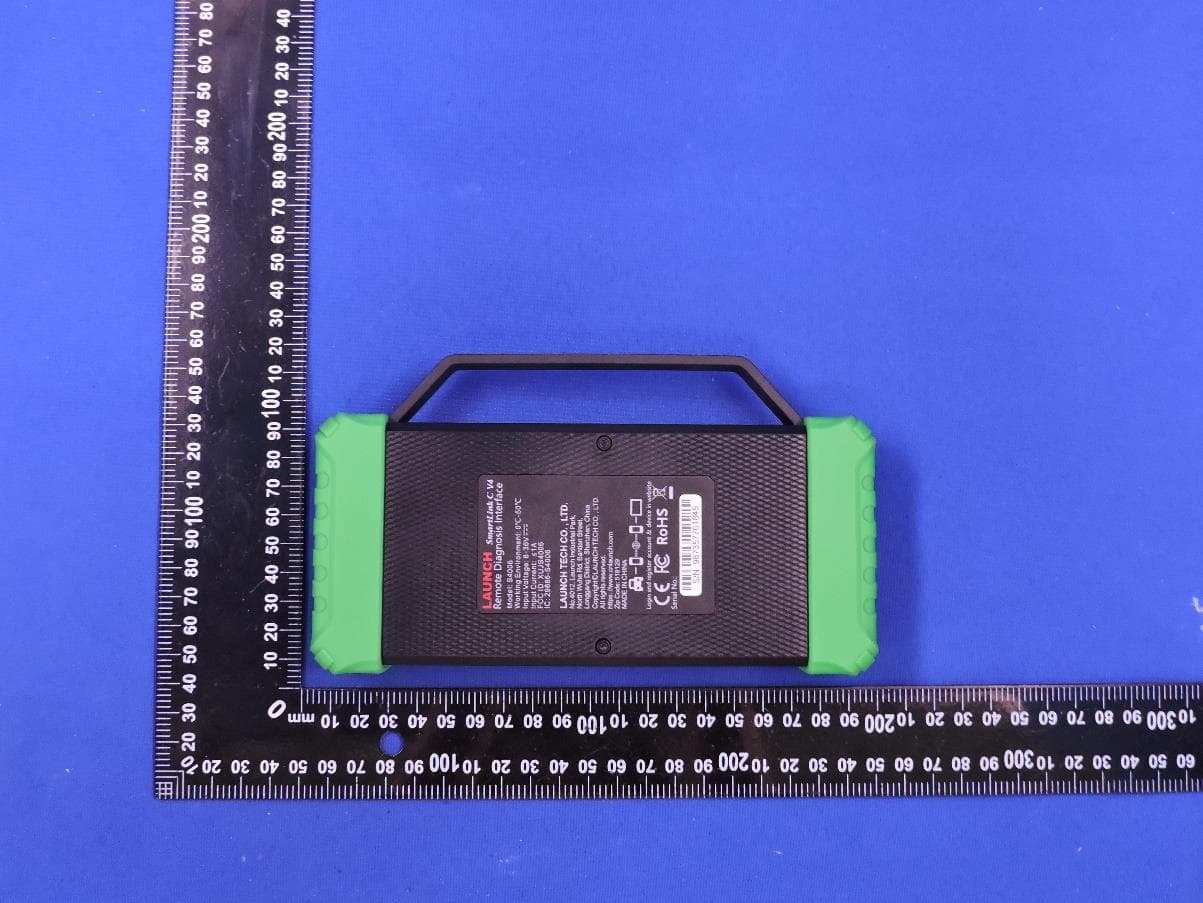
XUJS4006
Sep 04, 2026Remote Diagnosis Interface
Equipment Class
DTS - Digital Transmission SystemXUJEVT511S
Jul 09, 2026Battery Pack Airtightness Tester (High Voltage)
Equipment Class
DTS - Digital Transmission System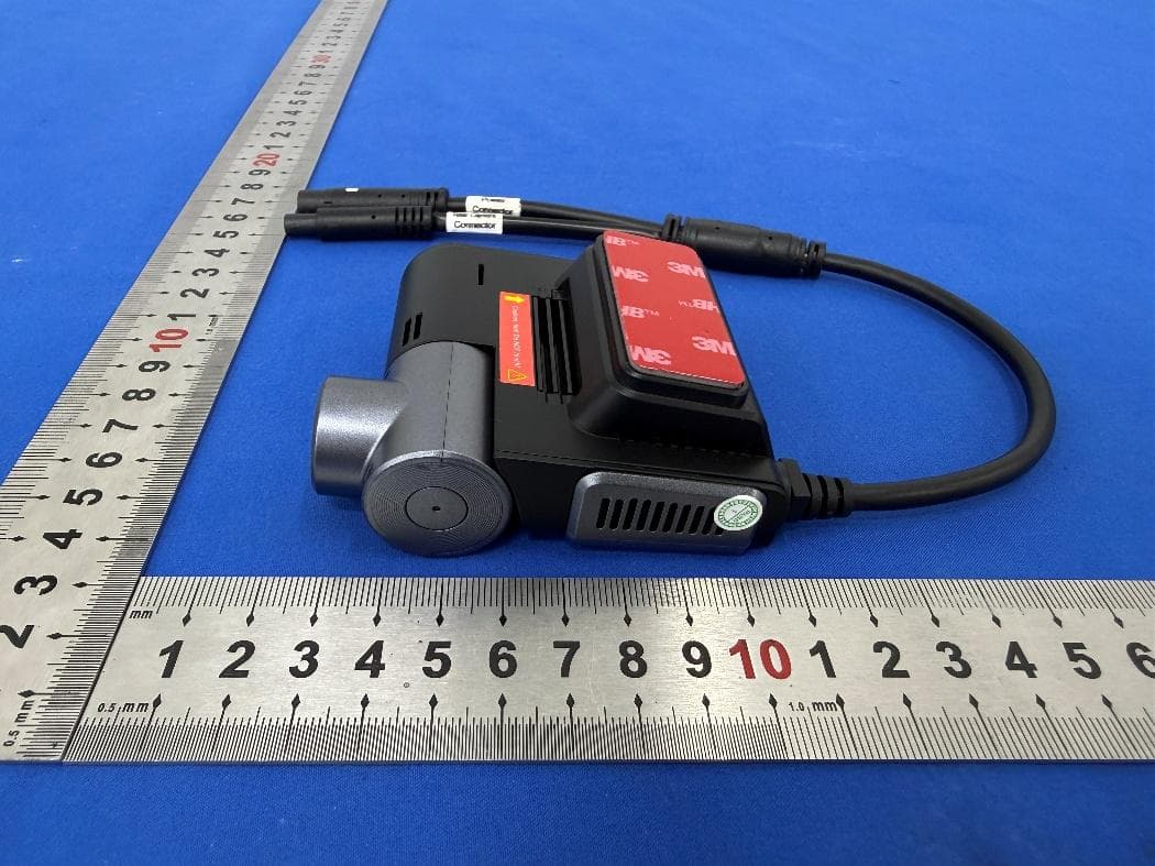
XUJG5201
Jun 26, 2026Car Sense Vision
Equipment Class
PCB - PCS Licensed Transmitter
XUJOADDPD1005A
Jun 05, 2026Automotive Diagnostic Tool
Equipment Class
NII - Unlicensed National Information Infrastructure TX