XUJWIFIPRWIFI Printer
Launch Tech Co., Ltd.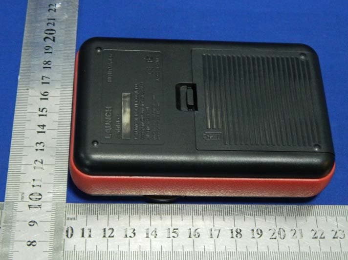
Click to zoom
Application Details
- Equipment Class
- DTS - Digital Transmission System
- Date of Grant
- Jan 05, 2014
- Application Purpose
- Original Equipment
- Date of Application
- Jan 05, 2014
- Equipment Note
- WIFI Printer
- Frequency Range
- 2422.00000000 - 2452.00000000
- Company
- Launch Tech Co., Ltd.
- Country
- China
Documents & Files
Document Text
Text extracted from the exhibit documents filed with the FCC. Open a document above to read the original.
Users Manual
WI-FI PRINTER User’s Manual LAUNCH TECH. CO., LTD. Launch Industrial Park, North of Wuhe Avenue, Banxuegang, Longgang, Shenzhen, Guangdong, P.R.China, 518129 Tel: +86-755-84528767 http://www.cnlaunch.com http://www.x431.com 1. Introduction This Wi-Fi printer is an optional accessory of a series of LAUNCH’s diagnostic devices. The built-in Wi-Fi module enables you to easily print the real time test results without connecting any USB cable. Compared to conventional printers, it is smaller and easier to carry. Meanwhile, being free of paper spindle, it is also simple and fast to load printing paper. In addition to the included DC power adaptor, it can be powered alternatively by the built-in rechargeable battery, which enables you to use it anytime and anywhere. Furthermore, this printer has auto-hibernate and auto power-off features. While it does not perform printing operation, it will enter auto sleeping mode to save power. If no activities are made within 30 minutes, it will power off automatically. To start printing, users need to power it on again. 2. Accessories a) DC adaptor x 1 b) Rechargeable Lithium battery x 1 c) Thermal printing paper x 1 3. General Controls test whether thermal paper is properly installed while the MODE indicator goes out. 6) CHARGE indicator [Green]: Indicates the battery is fully charged. [Red]: Indicates it is charging. 7) DC 9V adaptor jack (Note: The USB port next to it is disabled. Do not attempt to insert the cable into it.) 8) Rechargeable battery 4. Thermal paper loading This Wi-Fi printer applies thermal paper roll with size of Φ30×57mm. Follow the steps described as below to load it. 1. Hold the side notches on the front of the printer and lift it up to open the cover. 2. Place the unpacked thermal paper into 1 2 3 4 5 6 7 8 1) Side lock notch 2) Paper outlet 3) POWER button: Hold and press it for 2 seconds to turn it on/off. 4) MODE (ready) button: Press it to get the printer ready or switch it to manual feed mode. 5) FEED (paper test) button: Press it to the compartment with its starting end approaching to the paper outlet (refer to the figure shown as below). Reversing paper direction will result in that no results will be printed out. 3. Pull out some printing paper and introduce it along the slot until it comes out of the paper outlet shown as below. Otherwise, paper can not be fed. 4. Close the paper cover and press it down until you hear a click (see the figure shown on the next page). 5. Using the rechargeable battery The included rechargeable battery must be installed to ensure that the printer can print the test result normally. This printer utilizes a 7.2V, 1200mAh rechargeable Lithium battery. Do the following steps to install and charge it: 1. Align the latches on the bottom of the battery with the holes (shown as right) on the battery compartment. 2. Press the battery down until it is firmly fitted. 3. Press the [POWER] button for 2 seconds to turn it on. If the battery is low, the [POWER] indicator blinks. Please plug the included adaptor into an outlet to charge the battery in time. While charging, the charge indicator turns red. After charging is complete, the indicator will turn green. The normal charging time is 2 hours. Notes: A. Please use the included DC adaptor and rechargeable battery only. We assume no responsibilities for any personal injury or loss resulting from using other adaptors or rechargeable batteries not specified in this user manual. B. If the printer keeps unattended for a long period, please remove the rechargeable battery. 6. Wi-Fi connections Before printing, you need to make Wi-Fi connection and settings. Tap “1. Settings” on the main menu of your diagnostic tool. Tap “2. Wi-Fi” and slide its switch to ON. Locate and tap the 3. X-431PRINTER- XXX (XXX stands for 3 numbers). Input the identity password (default 4. factory value is 12345678) and tap “Connect”. “Connected” will appear on the screen once it is successful. 7. How to print test results There are three indicators on the printer: * [POWER]: Power indicator [Red]: Indicates that the printer is on. [Red and blink]: Indicates that the rechargeable battery is low. [Off]: Indicates the printer is off. * [MODE]: Ready indicator [Green]: Indicates that the printer is ready. [Green and blink]: Indicates that no thermal paper is loaded or the printer runs out of paper. [Off]: Indicates that the printer is switched to manual feed mode. * [FEED]: Paper test indicator [Green]: Indicates that users can press the [FEED] button to check whether the paper is fed normally. [Off]: Indicates that manual mode is off. Press the [POWER] button for 2 seconds to turn it on, the [MODE] indicator will blink and then remain on. (Every time you load or change the paper, press the [MODE] button to turn off the indicator first, and then press [FEED] to test whether paper can be fed normally.) When the [MODE] indicator is on, it shows that the printer is ready. If the printer icon appears on the top of the screen, it means that printing operation can be done. Tap it to start printing. Notes: A. Never expose the apparatus to sunshine, rain, or water. B. Make sure that this apparatus operates in the following conditions: Working temperature: -10 o C~50 o C Working humidity: 5 o C RH~90 o C RH. Statement: LAUNCH reserves the rights to make any change to product designs and specifications without notice. The actual object may differ a little from the descriptions in the manual in physical appearance, color and configuration. Notes: A. After loading the paper, users need to check whether the paper can be fed normally. For details, please refer to “How to print test results”. B. If the printer keeps printing for a long time, the thermal matrixes (shown as below) will overheat. To avoid a risk of burning injury, please do NOT touch the matrixes. Notice: The printer applies the thermal paper, which should be prevented from being heated before printing, otherwise, the paper would be no lon…
Text truncated - open the document above for the full version.
Cover Letter(s)
SCS-F18: Project and Product Certification Representative Authorization Letter Page 1 of 2 Rev 3.0 775 Montague Expressway Milpitas, CA 95035 Tel: 408-526-1188 Fax: 408-526-1088 Email: [email protected] Project and Product Certification Representative Authorization Letter Revision History Reason for Amendment (current / obsolete) From To Approved Date Initial Release (obsolete) 1.0 1.0 Nov-14-2006 Revised wording (obsolete) 1.0 2.0 Sept–25-2007 Updated company template (current) 2.0 3.0 Jan-31-2012 SCS-F18: Project and Product Certification Representative Authorization Letter Page 2 of 2 Rev 3.0 Launch Tech Co., Ltd. 2013-12-28 To: SIEMIC, INC. 775 Montague Expressway, Milpitas, CA 95035 USA Dear Sir/Madam, Re: Project and Product Certification Representative Authorization Letter We, Launch Tech Co., Ltd. hereby authorize SIEMIC, INC. to act as a Certification Body for certifying for the following project(s): FCC ID: XUJWIFIPR (WIFI Printer Model No.: WIFI Printer) We affirm that between SIEMIC and Launch Tech Co., Ltd., any difference in understanding, including test plan, measurement methods, applicable standards and relevant procedures and processes have been resolved prior to commencement of testing activities. Sincerely, Yibing Xue/Manager E-mail: [email protected] Phone: (86) 755-84528031 Fax: (86) 755-84528889 Address: Launch Industrial Park, North of Wuhe Rd., Banxuegang, Longgang, Shenzhen, China
Cover Letter(s)
Confidentiality Request Letter Launch Tech Co., Ltd. 2013-12-28 To: Federal Communications Commission Office of Engineering and Technology Equipment Authorization Division 7345 Oakland Mills Road Columbia, Maryland 21046 Subject: Permanent Confidentiality Request for FCC ID: XUJWIFIPR We hereby request confidential treatment of information accompanying this application as outlined below: - Block diagram - Operation description - Schematic The above materials contain trade secrets and proprietary information not customarily released to the public. The public disclosure of these materials may be harmful to the applicant and provide unjustified benefits to its competitors. The applicant understands that pursuant to Section 0.457 & 0.459 of the Rules, disclosure of this application and all accompanying documentation will not be made before the date of the Grant for this application. Sincerely, Yibing Xue/Manager E-mail: [email protected] Phone: (86) 755-84528031 Fax: (86) 755-84528889 Address: Launch Industrial Park, North of Wuhe Rd., Banxuegang, Longgang, Shenzhen, China
ID Label/Location Info
Label Location Proposed Label Location on EUT
Internal Photos
Antenna Wifi Module
RF Exposure Info
FCC ID : XUJWIFIPR RF EXPOSURE EVALUATION According to FCC 1.1310: The criteria listed in the following table shall be used to evaluate the environment impact of human exposure to radio frequency(RF) Radiation as specified in §1.1307(b) Limits for Maximum Permissible Exposure(MPE) Frequency Range(MHz) Electric Field Strength(V/m) Magnetic Field Strength(A/m) Power Density(mW/cm 2 ) Average Time (A) Limits for Occupational/Control Exposures 300-1500 -- -- F/300 6 1500-100000 -- -- 5 6 (B) Limits for General Population/Uncontrol Exposures 300-1500 -- -- F/1500 6 1500-100000 -- -- 1 30 11.1 Friis transmission formula: Pd=(Pout*G)\(4*pi*R 2 ) Where Pd= Power density in mW/cm 2 Pout=output power to antenna in mW G= Numeric gain of the antenna relative to isotropic antenna Pi=3.1416 R= distance between observation point and center of the radiator in cm Pd the limit of MPE, 1mW/cm 2 . If we know the maximum gain of the antenna and total power input to the antenna, through the calculation, we will know the distance where the MPE limit is reached. 11.2 Measurement Result Power density limited: 1mW/ cm 2 Antenna gain:2.51 dBi Max Output Peak power (dBm) Output Peak power (mW) Antenna Gain (dBi) Numeric Power density at 20cm (mW/ cm 2 ) Power density Limits (mW/cm 2 ) 16.96 49.66 1.78 0.02 1
Test Report
TRF No:FCC 15.247/A Page 1 of 60 Report No ES131125185E Shenzhen EMTEK Co.,Ltd. Building 69, Majialong Industry Zone, Nanshan District, Shenzhen,Guangdong,China www.emtek.com.cn Tel: +86-755-2695 4280 Fax: +86-755-2695 4282 Access to the World ELECTROMAGNETIC EMISSIONS COMPLIANCE REPORT INTENTIONAL RADIATOR CERTIFICATION TO FCC PART 15 SUBPART C REQUIREMENT OF WIFI Printer MODEL No.: WIFI Printer FCC ID: XUJWIFIPR Trademark: LAUNCH REPORT NO: ES131125185E ISSUE DATE: December 21, 2013 Prepared for Launch Tech Co., Ltd. Launch Industrial Park, North of Wuhe Rd., Banxuegang, Longgang, Shenzhen, China Prepared by SHENZHEN EMTEK CO., LTD. Bldg 69, Majialong Industry Zone, Nanshan District, Shenzhen, Guangdong, China TEL: 86-755-26954280 FAX: 86-755-26954282 TRF No:FCC 15.247/A Page 2 of 60 Report No ES131125185E Shenzhen EMTEK Co.,Ltd. Building 69, Majialong Industry Zone, Nanshan District, Shenzhen,Guangdong,China www.emtek.com.cn Tel: +86-755-2695 4280 Fax: +86-755-2695 4282 Access to the World VERIFICATION OF COMPLIANCE Applicant: Launch Tech Co., Ltd. Launch Industrial Park, North of Wuhe Rd., Banxuegang, Longgang, Shenzhen, China Manufacturer: Launch Tech Co., Ltd. Launch Industrial Park, North of Wuhe Rd., Banxuegang, Longgang, Shenzhen, China Product Description: WIFI Printer Model Number: WIFI Printer File Number: ES131125185E Date of Test: December 11, 2013 to December 21, 2013 We hereby certify that: The above equipment was tested by SHENZHEN EMTEK CO., LTD. The test data, data evaluation, test procedures, and equipment configurations shown in this report were made in accordance with the procedures given in ANSI C63.4 (2009) and the energy emitted by the sample EUT tested as described in this report is in compliance with conducted and radiated emission limits of FCC Rules Part 15.247. The test results of this report relate only to the tested sample identified in this report. Date of Test : December 11, 2013 to December 21, 2013 Prepared by : Joe Xia/Editor Reviewer : June xie/Supervisor Approve & Authorized Signer : Lisa Wang/Manager TRF No:FCC 15.247/A Page 3 of 60 Report No ES131125185E Shenzhen EMTEK Co.,Ltd. Building 69, Majialong Industry Zone, Nanshan District, Shenzhen,Guangdong,China www.emtek.com.cn Tel: +86-755-2695 4280 Fax: +86-755-2695 4282 Access to the World Ta b l e o f C o n t e n t s 1. GENERAL INFORMATION ................................................................................................................................ 5 1.1 PRODUCT DESCRIPTION.................................................................................................................................... 5 1.2 RELATED SUBMITTAL(S) / GRANT(S)................................................................................................................. 5 1.3 TEST METHODOLOGY....................................................................................................................................... 6 1.4 SPECIAL ACCESSORIES...................................................................................................................................... 6 1.5 EQUIPMENT MODIFICATIONS............................................................................................................................ 6 1.6 TEST FACILITY.................................................................................................................................................. 6 2. SYSTEM TEST CONFIGURATION ................................................................................................................... 7 2.1 EUT CONFIGURATION....................................................................................................................................... 7 2.2 EUT EXERCISE................................................................................................................................................. 7 2.3 TEST PROCEDURE............................................................................................................................................. 7 2.4 CONFIGURATION OF TESTED SYSTEM............................................................................................................... 7 3. DESCRIPTION OF TEST MODES ..................................................................................................................... 9 4. SUMMARY OF TEST RESULTS....................................................................................................................... 10 5. CONDUCTED EMISSIONS TEST.................................................................................................................... 11 5.1 MEASUREMENT PROCEDURE.......................................................................................................................... 11 5.2 TEST SET-UP (BLOCK DIAGRAM OF CONFIGURATION) .................................................................................. 11 5.3 MEASUREMENT EQUIPMENT USED................................................................................................................. 11 5.4 CONDUCTED EMISSION LIMIT......................................................................................................................... 11 5.5 MEASUREMENT RESULT.................................................................................................................................. 12 6. RADIATED EMISSION TEST ........................................................................................................................... 13 6.1 MEASUREMENT PROCEDURE.......................................................................................................................... 13 6.2 TEST SET-UP (BLOCK DIAGRAM OF CONFIGURATION) .................................................................................. 13 6.3 MEASUREMENT EQUIPMENT USED................................................................................................................. …
Text truncated - open the document above for the full version.
Contact Information
Applicant
Ivy Zhong(Manager)
Test Firm
EMTEK (Shenzhen) Co., Ltd.David Lee
Technical Specifications
| # | Rule Parts | Frequency Range | Power Output |
|---|---|---|---|
| 2 | 15C | 2.42 GHz - 2.45 GHz | 23.00 mW |
Other Applications from Launch Tech Co., Ltd.
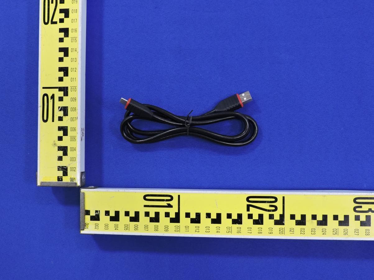
XUJOADDPD1303A
Sep 17, 2026Automotive Diagnostic Tool
Equipment Class
DTS - Digital Transmission System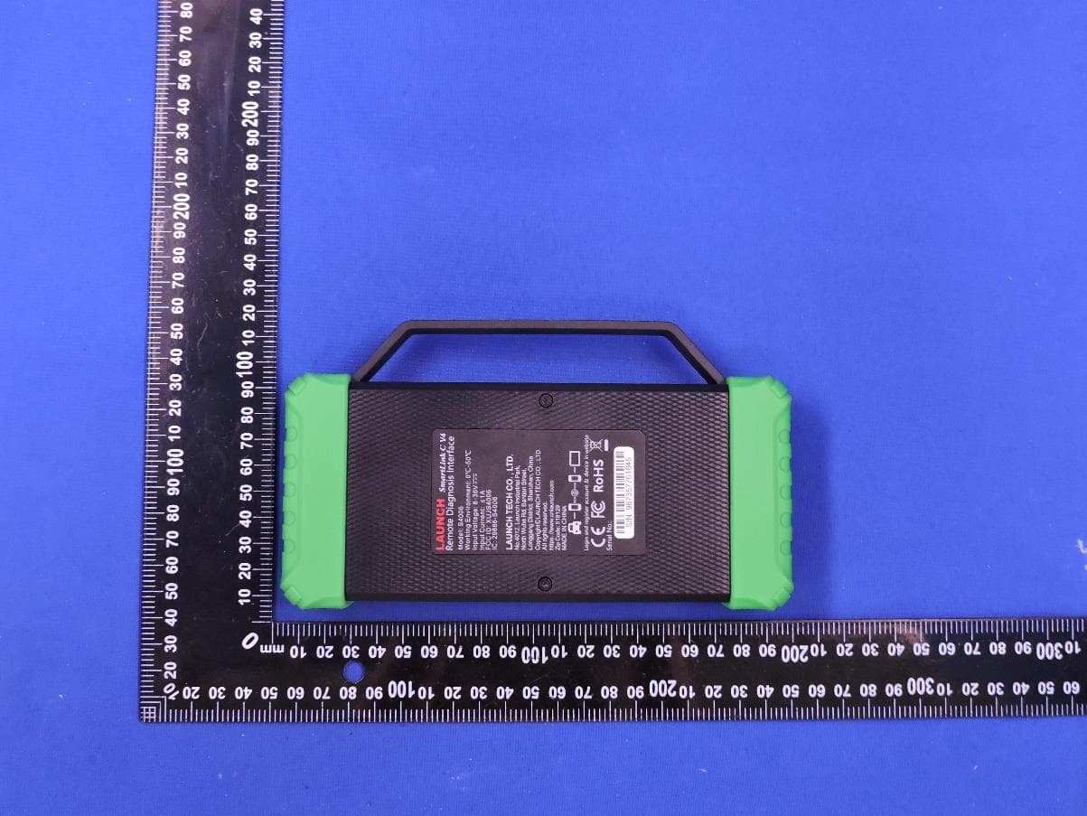
XUJS4006
Sep 04, 2026Remote Diagnosis Interface
Equipment Class
DTS - Digital Transmission SystemXUJEVT511S
Jul 09, 2026Battery Pack Airtightness Tester (High Voltage)
Equipment Class
DTS - Digital Transmission System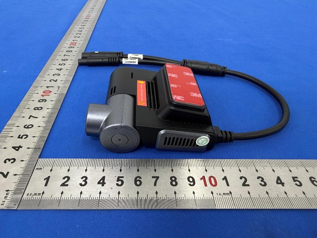
XUJG5201
Jun 26, 2026Car Sense Vision
Equipment Class
PCB - PCS Licensed Transmitter
XUJOADDPD1005A
Jun 05, 2026Automotive Diagnostic Tool
Equipment Class
NII - Unlicensed National Information Infrastructure TX