XUJX431HDMAutomotive Diagnostic Adaptor Box
Launch Tech Co., Ltd.Application Details
- Equipment Class
- DSS - Part 15 Spread Spectrum Transmitter
- Date of Grant
- Nov 03, 2014
- Application Purpose
- Original Equipment
- Date of Application
- Nov 03, 2014
- Equipment Note
- Automotive Diagnostic Adaptor Box
- Frequency Range
- 2402.00000000 - 2480.00000000
- Company
- Launch Tech Co., Ltd.
- Country
- China
Documents & Files
Document Text
Text extracted from the exhibit documents filed with the FCC. Open a document above to read the original.
Users Manual
X-431 HD Module User’s Manual (V1.00.000) Disclaimer While using this product, please pay more attention to the following: y Follow instructions to connect the X-431 HD module to your vehicle before using. y While you are driving a car, do not attempt to operate this product, so as to avoid distraction and traffic hazard. The company assumes no responsibilities for any traffic accident or economic loss resulting from operating it while driving. y This product collects and sends data via Bluetooth communication. Avoid using this product near a place with strong electromagnetic interference to ensure a normal transmission. y Any problem related to this product should be solved by our professional technical personnel. The company has the obligation to make some repair or replacements to this product according to the actual conditions. This user manual is subject to change without prior notice due to continuous innovation. FCC STATEMENT 1. This device complies with Part 15 of the FCC Rules. Operation is subject to the following two conditions: (1) This device may not cause harmful interference. (2) This device must accept any interference received, including interference that may cause undesired operation. 2. Changes or modifications not expressly approved by the party responsible for compliance could void the user's authority to operate the equipment. NOTE: This equipment has been tested and found to comply with the limits for a Class B digital device, pursuant to Part 15 of the FCC Rules. These limits are designed to provide reasonable protection against harmful interference in a residential installation. This equipment generates uses and can radiate radio frequency energy and, if not installed and used in accordance with the instructions, may cause harmful interference to radio communications. However, there is no guarantee that interference will not occur in a particular installation. If this equipment does cause harmful interference to radio or television reception, which can be determined by turning the equipment off and on, the user is encouraged to try to correct the interference by one or more of the following measures: y Reorient or relocate the receiving antenna. y Increase the separation between the equipment and receiver. y Connect the equipment into an outlet on a circuit different from that to which the receiver is connected. y Consult the dealer or an experienced radio/TV technician for help. X-431 Heavy-duty module is specifically designed to diagnose diesel and gas-fueled heavy-duty vehicle models of 12V & 24V voltage. 1 Knowledge of X-431 HD Module 1.1 Features 1. Applicable to diesel vehicle of 12V & 24V voltage; no need for battery conversion when testing 24V trucks; 2. Supports a wide range of vehicle models covering Asian, American and European etc; 3. Powerful testing function enables you to diagnose all electronic control system; 4. International design to adapt to all diagnostic sockets. 1.2 Ports and Indicators of X-431 HD Module Fig. 1-1 Ports and indicators of X-431 HD module No. Name Notes Indicators (from left to right) Power indicator It lights up when X-431 HD module is powered up. Diagnostic tool communication indicator It lights up when X-431 HD module is communicating with the diagnostic tool. Vehicle communication indicator It lights up when X-431 HD module is communicating with vehicle’s DLC. 1 Serial port communication It illuminates when X-431 HD module is connected to PC via serial port cable. indicator USB status indicator It illuminates blue after USB cable is properly connected to X-431 HD module. (Currently disabled, for subsequent function extension.) Wi-Fi indicator It lights up when Wi-Fi / Bluetooth toggle switch is in Wi-Fi mode. Bluetooth indicator It lights up when Wi-Fi / Bluetooth toggle switch is in Bluetooth mode. Battery working indicator Press the power switch, it will light up; To put it out, press it again. Charging indicator It illuminates green while being charged; once fully charged, it goes out. (Note: In general, the charging time is about 1-2 hours.) 2 Wi-Fi / Bluetooth toggle switch To toggle between Wi-Fi and Bluetooth. 3 PC communication port To connect to the serial port of PC. (Currently disabled, for subsequent function extension.) 4 USB port To connect the B-shaped terminal of USB cable. 5 Diagnostic socket To connect the main cable. 6 Power switch of Wi-Fi and Bluetooth module To turn on/off the power supply of Wi-Fi & Bluetooth module. (Note: This switch is not intended to manage the power supply of X-431 HD module.) 7 Power interface To connect the power adaptor of X-431HD module. 1.3 Technical Parameters Working voltage: 8~24V Working temperature: -15°C ~ 60°C Storage temperature: -20°C ~ 70°C Relative humidity: 10% ~ 80% Dimension: 110 mm * 178 mm * 50 mm 2 Connections 2.1 How to connect OBD II vehicle Follow the steps described below to proceed: 1. Locate vehicle’s DLC socket. The DLC is usually located 12 inches from the center of the instrument panel (dash), under or around the driver’s side for most vehicles. If Data Link Connector is not located under dashboard, a label should be there telling location. If the DLC cannot be found, refer to the vehicle’s service manual for the location. Fig. 2-1 2. Connect one end of the main cable to the diagnostic socket, and then connect other end to the vehicle’s DLC (For non-16 pin DLC, you need to choose the corresponding diagnostic connector). See Fig. 5-3. Fig. 2-2 2.2 How to connect non-OBD II vehicle Choose one of the following to connect non-OBD II vehicle: 1. Via Cigarette Lighter 2. Via Battery Clamps Cable 2.3 Download and Install X-431 HD Module App 1. Visit the LAUNCH website and download the application corresponding to X-431 HD module; Note: If downloading using the diagnostic tool please make sure Wi-Fi has good or strong signals. 2. Follow the on-screen instructions to install it. Once installation is complete, an application icon will appear on th…
Text truncated - open the document above for the full version.
Users Manual
FCC INFORMATION (additional) RF Exposure: A distance of 20 cm shall be maintained between the antenna and users, and the transmitter may not be co-located with any other transmitter or antenna.
Cover Letter(s)
Launch Tech Co., Ltd. Launch Industrial Park, North of Wuhe Rd., Banxuegang,Longgang,Shenzhen,518129, China FCC Confidentiality Request Number: CF303 Version: V01 Date: 01-02-2010 To the FCC and FCC TCB handling this application for certification Pursuant to 47 CFR Section 0.459(a) & (b), we, (the applicant / grantee) Company name Launch Tech Co., Ltd. Addresss Launch Industrial Park, North of Wuhe Rd., Banxuegang, Longgang,Shenzhen,518129,China City Shenzhen Country China FF request non-disclosure and confidential treatment for our certification under: Grantee Code Product Number FCC ID: XUJ X431HDM of the following materials submitted within this certification application: (please cross what is applicable, or add other documents) √ Operational Description √ Block Diagrams √ Schematics Diagrams Above materials contain secrets, proprietary and technical information, which would customarily be guarded from competitors under 47 CFR, section 0.457(d)(2). Disclosure or publication or any portion of this company confidential material to other parties could cause substantial competitive harm and provide unjustified benefits for competitors. We understand that pursuant to 47 CFR section 0.457(d)(1)(ii) disclosure of the applicant and all accompanying documentation will not be made before the date of the grant. Attestation: City and Country: Date: Name: (this must be a person) Function: Signature: (or official company stamp) Shenzhen China 2014-09-29 Yibing Xue manager
External Photos
Report No: C140904Z02-RP1 Page 1 / 3 External Photos of EUT Report No: C140904Z02-RP1 Page 2 / 3 Report No: C140904Z02-RP1 Page 3 / 3
ID Label/Location Info
FCC ID: XUJX431HDM Label and location
Internal Photos
Report No: C140904Z02-RP1 Page 1 / 4 Internal Photos of EUT Report No: C140904Z02-RP1 Page 2 / 4 Report No: C140904Z02-RP1 Page 3 / 4 RF Module Report No: C140904Z02-RP1 Page 4 / 4
RF Exposure Info
Compliance Certification Services Inc. Report No: C140904Z02 _MPE FCC ID: XUJX431HDM Date of Issue: October 9, 2014 1 RADIO FREQUENCY EXPOSURE LIMIT Systems operating under the provisions of this section shall be operated in a manner that ensures that the public is not exposed to radio frequency energy levels in excess of the Commission's guidelines. See §15.247(b)(4) and §1.1307(b)(1) of this chapter. EUT Specification EUT Automotive Diagnostic Adaptor Box Frequency band (Operating) WLAN: 2.412GHz ~ 2.462GHz WLAN: 5.18GHz ~ 5.32GHz / 5.50GHz ~ 5.70GHz WLAN: 5.745GHz ~ 5825GHz Bluetooth: 2.402GHz~ 2.480GHz Others Device category Portable (<20cm separation) Mobile (>20cm separation) Others __________________________ Exposure classification Occupational/Controlled exposure (S = 5mW/cm 2 ) General Population/Uncontrolled exposure (S=1mW/cm 2 ) Antenna diversity Single antenna Multiple antennas Tx diversity Rx diversity Tx/Rx diversity Max. output power 0.15dBm (1.04mW) Antenna gain (Max) 2dBi (Numeric gain:1.58) Evaluation applied MPE Evaluation SAR Evaluation Note: 1. The maximum output power is 0.15dBm (1.04mW) at 2480MHz (with 1.58 numeric antenna gain.) 2. For mobile or fixed location transmitters, no SAR consideration applied. The minimum separation generally be used is at least 20 cm, even if the calculations indicate that the MPE distance would be lesser. TEST RESULT No non-compliance noted. Compliance Certification Services Inc. Report No: C140904Z02 _MPE FCC ID: XUJX431HDM Date of Issue: October 9, 2014 2 Calculation Given 2 4d GP S Π × = Equation 1 Where d = distance in cm P = Power in mW G = Numeric antenna gain S = Power Density in mW / cm 2 Maximum Permissible Exposure EUT Output Power= 1.04mW Numeric antenna gain=1.58 Substituting the MPE safe distance using d=20 cm into Equation 1 : Fields The power density S = 1.04 × 1.58/ (4∏ × 400) cm 2 =3.27*e -4 mW/cm 2 (For mobile or fixed location transmitters, the maximum power density is 1.0 mW / cm 2 even if the calculation indicates that the power density would be larger.)
Test Report
Report No.: C140904Z02-RP1 Note: This report shall not be reproduced except in full, without the written approval of Compliance Certification Services Inc. This document may be altered or revised by Compliance Certification Services Inc. personnel only, and shall be noted in the revision section of the document. The client should not use it to claim product endorsement by TAF, A2LA, NVLAP, NIST or any government agencies. The test result of this report relate only to the tested sample identified in this report. FCC ID: XUJX431HDM Page 1 / 57 FCC 47 CFR PART 15 SUBPART C TEST REPORT For Automotive Diagnostic Adaptor Box Model: X-431 HD Module Brand: LAUNCH Test Report Number: C140904Z02-RP1 Prepared for Launch Tech Co., Ltd. Launch Industrial Park, North of Wuhe Rd., Banxuegang, Longgang, Shenzhen, 518129, China Prepared by COMPLIANCE CERTIFICATION SERVICES (SHENZHEN) INC. No.10-1, Mingkeda Logistics Park, No.18, Huanguan South Rd., Guan Lan Town, Baoan District, Shenzhen China TEL: 86-755-28055000 FAX: 86-755-28055221 Issued Date: October 9, 2014 检 测 CNAS L4818 Report No.: C140904Z02-RP1 FCC ID: XUJX431HDM Page 2 of 57 This report shall not be reproduced except in full, without the written approval of Compliance Certification Services. Revision History Rev. Issue Date Revisions Effect Page Revised By 00 October 9, 2014 Initial Issue ALL Nancy Fu Report No.: C140904Z02-RP1 FCC ID: XUJX431HDM Page 3 of 57 This report shall not be reproduced except in full, without the written approval of Compliance Certification Services. TABLE OF CONTENTS 1. TEST RESULT CERTIFICATION .....................................................................................4 2. EUT DESCRIPTION..........................................................................................................5 3. TEST METHODOLOGY....................................................................................................6 3.1 DESCRIPTION OF TEST MODES ................................................................................6 4. FACILITIES AND ACCREDITATIONS .............................................................................7 4.1 FACILITIES....................................................................................................................7 4.2 ACCREDITATIONS .......................................................................................................7 4.3 MEASUREMENT UNCERTAINTY ................................................................................7 5. SETUP OF EQUIPMENT UNDER TEST ..........................................................................8 5.1 SETUP CONFIGURATION OF EUT .............................................................................8 5.2 SUPPORT EQUIPMENT .............................................................................................8 6. FCC PART 15.247 REQUIREMENTS ..............................................................................9 6.1 20dB BANDWIDTH........................................................................................................9 6.2 PEAK POWER.............................................................................................................13 6.3 PEAK POWER SPECTRAL DENSITY ........................................................................15 6.4 BAND EDGES MEASUREMENT ................................................................................16 6.5 FREQUENCY SEPARATION ......................................................................................26 6.6 NUMBER OF HOPPING FREQUENCY ......................................................................29 6.7 TIME OF OCCUPANCY (DWELL TIME) .....................................................................31 6.8 SPURIOUS EMISSIONS .............................................................................................38 6.9 POWERLINE CONDUCTED EMISSIONS ..................................................................56 Report No.: C140904Z02-RP1 FCC ID: XUJX431HDM Page 4 of 57 This report shall not be reproduced except in full, without the written approval of Compliance Certification Services. 1. TEST RESULT CERTIFICATION Product Automotive Diagnostic Adaptor Box Model X-431 HD Module Brand LAUNCH Tested September 4~ October 9, 2014 Applicant Launch Tech Co., Ltd. Launch Industrial Park, North of Wuhe Rd., Banxuegang, Longgang, Shenzhen, 518129, China Manufacturer Launch Tech Co., Ltd. Launch Industrial Park, North of Wuhe Rd., Banxuegang, Longgang, Shenzhen, 518129, China APPLICABLE STANDARDS STANDARD TEST RESULT FCC 47 CFR Part 15 Subpart C No non-compliance noted We hereby certify that: The above equipment was tested by Compliance Certification Services Inc. The test data, data evaluation, test procedures, and equipment configurations shown in this report were made in accordance with the procedures given in ANSI C63.4:2009 and the energy emitted by the sample EUT tested as described in this report is in compliance with conducted and radiated emission limits of FCC Rules Part 15.207, 15.209 and 15.247. The test results of this report relate only to the tested sample EUT identified in this report. Approved by: Reviewed by: Sunday Hu Supervisor of EMC Dept. Compliance Certification Service Inc. Ruby Zhang Supervisor of Report Dept. Compliance Certification Service Inc. Report No.: C140904Z02-RP1 FCC ID: XUJX431HDM Page 5 of 57 This report shall not be reproduced except in full, without the written approval of Compliance Certification Services. 2. EUT DESCRIPTION Product Automotive Diagnostic Adaptor Box Model Number X-431 HD Module Brand LAUNCH Model Discrepancy N/A Identify Number C140904Z02-RP1 Power Supply DC12V supplied by the DC power supply Received Date September 4, 2014 Frequency Range 2402 ~ 2480 MHz Transmit Power GFSK : 0.15dBm 8DPSK : -0.78dBm Modulation Technique FHSS (GFSK for 1Mbps, π/4-DQPSK for 2Mbps, 8DPSK for 3Mbps) Number of Channels 79 Channels Antenna Specification PCB Antenna w…
Text truncated - open the document above for the full version.
Test Setup Photos
Report No.: C140904Z02-RP1 FCC ID: XUJX431HDM Page 1/2 PHOTOGRAPHS OF THE TEST CONFIGURATION RADIATED EMISSION TEST Below 1GHz Above 1GHz
Contact Information
Applicant
Ivy Zhong(Manager)
Test Firm
Compliance Certification Services (Shenzhen) Inc.Harry Li
Technical Specifications
| # | Rule Parts | Frequency Range | Power Output |
|---|---|---|---|
| 1 | 15C | 2.40 GHz - 2.48 GHz | 1.04 mW |
Other Applications from Launch Tech Co., Ltd.
XUJOADDPD1303A
Sep 17, 2026Automotive Diagnostic Tool
Equipment Class
DTS - Digital Transmission System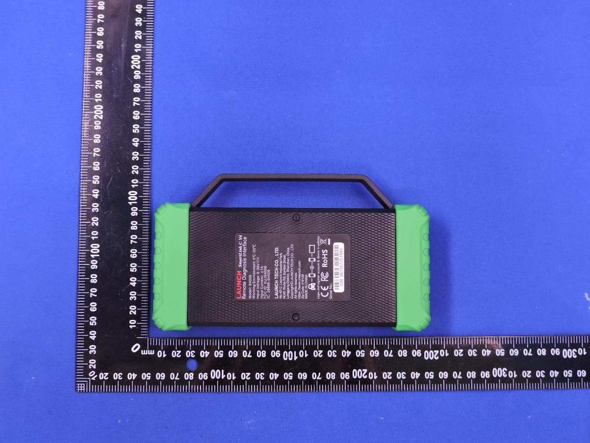
XUJS4006
Sep 04, 2026Remote Diagnosis Interface
Equipment Class
DTS - Digital Transmission SystemXUJEVT511S
Jul 09, 2026Battery Pack Airtightness Tester (High Voltage)
Equipment Class
DTS - Digital Transmission System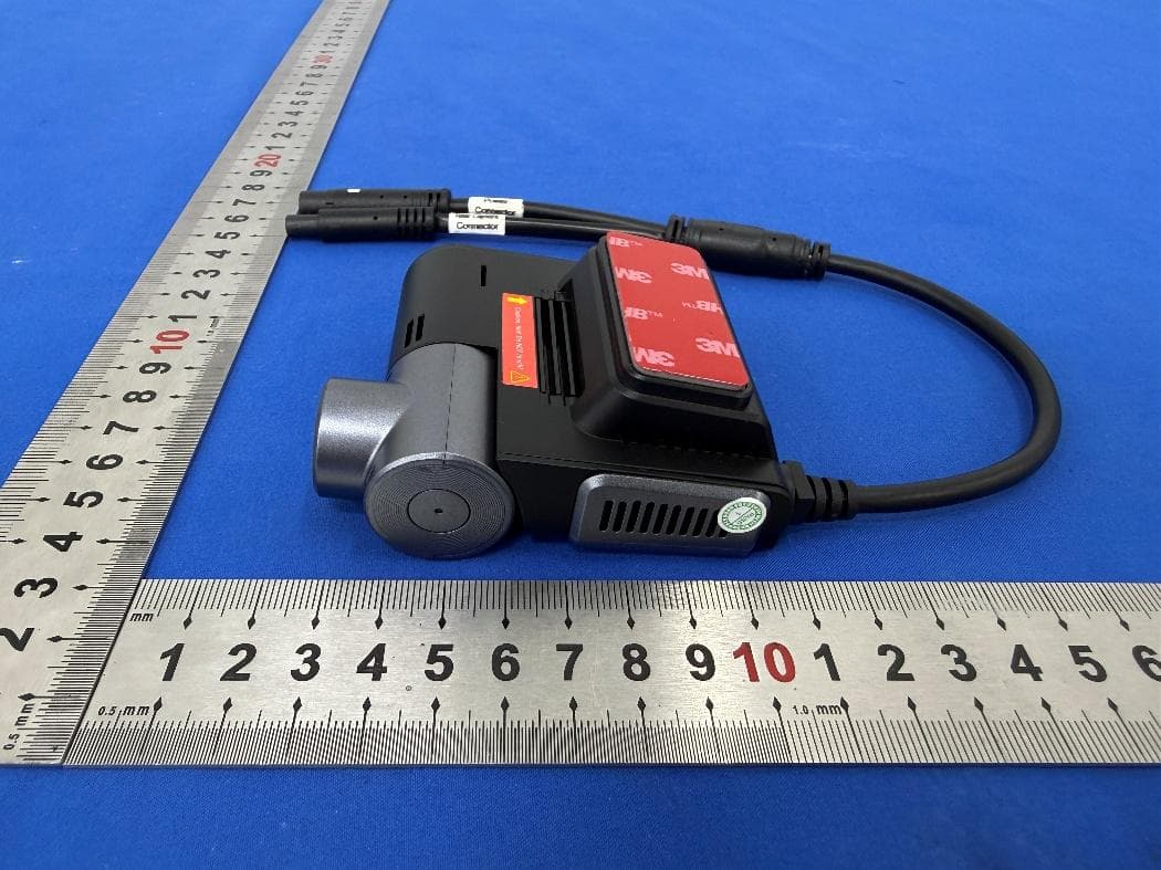
XUJG5201
Jun 26, 2026Car Sense Vision
Equipment Class
PCB - PCS Licensed Transmitter
XUJOADDPD1005A
Jun 05, 2026Automotive Diagnostic Tool
Equipment Class
NII - Unlicensed National Information Infrastructure TX