XUJX431TOOLAUTOMOTIVE DIAGNOSIS COMPUTER
Launch Tech Co., Ltd.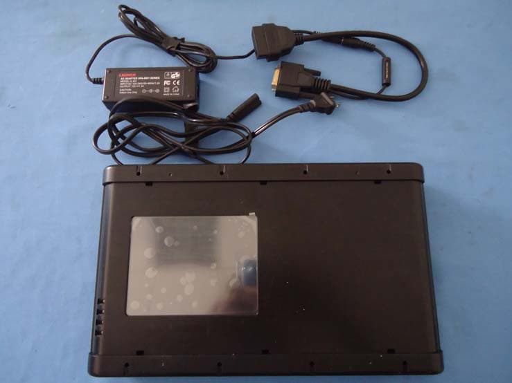
Click to zoom
Application Details
- Equipment Class
- DSS - Part 15 Spread Spectrum Transmitter
- Date of Grant
- Aug 30, 2011
- Application Purpose
- Original Equipment
- Date of Application
- Aug 30, 2011
- Equipment Note
- AUTOMOTIVE DIAGNOSIS COMPUTER
- Frequency Range
- 2402.00000000 - 2480.00000000
- Company
- Launch Tech Co., Ltd.
- Country
- China
Documents & Files
Document Text
Text extracted from the exhibit documents filed with the FCC. Open a document above to read the original.
Users Manual
V1.00.001 2011-04-07 LAUNCH X-431Tool User’s Manual i Trademark Information LAUNCH is a registered trademark of LAUNCH TECH. CO., LTD. (also called LAUNCH for short) in China and other countries. All other LAUNCH trademarks, service marks, domain names, logos, and company names referred to in this manual are either trademarks, registered trademarks, service marks, domain names, logos, company names of or are otherwise the property of LAUNCH or its affiliates. In countries where any of the LAUNCH trademarks, service marks, domain names, logos and company names are not registered, LAUNCH claims other rights associated with unregistered trademarks, service marks, domain names, logos, and company names. Other products or company names referred to in this manual may be trademarks of their respective owners. You may not use any trademark, service mark, domain name, logo, or company name of LAUNCH or any third party without permission from the owner of the applicable trademark, service mark, domain name, logo, or company name. You may contact LAUNCH by visiting Launch at http:// www. cnlaunch. com , or writing to LAUNCH TECH. CO., LTD.,Launch Industrial Park,North of Wuhe Avenue, Banxuegang, Bantian, Longgang, Shenzhen, Guangdong,P. R . C h i n a , to request written permission to use Materials on this manual for purposes or for all other questions relating to this manual. Copyright Information Copyright © 2011 by LAUNCH TECH. CO., LTD. All rights reserved. No part of this publication may be reproduced, stored in a retrieval system, or transmitted in any form or by any means, electronic, mechanical, photocopying, recording or otherwise, without the prior written permission of LAUNCH. The information contained herein is designed only for the use of this unit. LAUNCH is not responsible for any use of this information as applied to other units. Neither LAUNCH nor its affiliates shall be liable to the purchaser of this unit or third parties for damages, losses, costs, or expenses incurred by purchaser or third parties as a result of: accident, misuse, or abuse of this unit, or unauthorized modifications, repairs, or alterations to this unit, or failure to strictly comply with LAUNCH operating and maintenance instructions. LAUNCH shall not be liable for any damages or problems arising from the use of any options or any consumable products other than those designated as Original LAUNCH Products or LAUNCH Approved Products by LAUNCH. General Notice z Other product names used herein are for identification purposes only and may be trademarks of their respective owners. LAUNCH disclaims any and all rights in those marks. z There is a possibility that this unit is inapplicable to some of the vehicle models or systems listed in the diagnosis section due to different countries, areas, and/or years. Do not hesitate to contact LAUNCH if you come across such questions. We are to help you solve the problem as soon as possible. Disclaimer z To take full advantage of the unit, you should be familiar with the engine. z All information, illustrations, and specifications contained in this manual are based on the latest information available at the time of publication. The right is reserved to make change at any time without notice. LAUNCH X-431Tool User’s Manual ii Table of Contents Introduction.......................................................2 Features.........................................................2 Outline of X-431TOOL......................................3 Structure and explanations...............................4 Ports and Indicators.........................................5 Hardware Configuration...................................5 Printer Operation.............................................7 Mounting Paper...........................................7 Specifications..................................................8 First Use of X-431TOOL...................................9 Start-up......................................................9 Taskbar......................................................9 Input........................................................10 Control of App...........................................11 Help.........................................................11 Vehicle Diagnosis............................................12 Conditions for Test.........................................12 Select Diagnostic Connector...........................12 Diagnostic Socket Location.............................12 Connection...................................................12 Operation......................................................13 Entering Function Menu.............................13 Control module..........................................14 Resetting Maintain/oil Indicator.......................24 Setting Service Code.....................................25 OBDII Diagnostic function...........................25 Freeze Frame Data...................................25 Readiness Test.........................................26 Diagnostic Socket Description.........................26 Update of diagnostic software.........................27 User Registration.......................................27 Software Update.......................................28 Flow Chart of X-431TOOL Update for New User ....................................................................33 PDA function....................................................34 System information........................................ 36 User Information....................................... 36 About....................................................... 36 Tool.............................................................. 36 PIM.............................................................. 39 Memo...................................................... 39 Address.................................................... 41 Delete Address......................................... 42 To D o................................................…
Text truncated - open the document above for the full version.
Cover Letter(s)
Date:2011-8-11 To: Federal Communications Commission 7435 Oakland Mills Road Columbia, MD FCC ID:XUJX431TOOL To Whom It May Concern: Launch Tech Co., Ltd. This letter is to ascertain that SCM Microsystems, Inc. Product AUTOMOTIVE DIAGNOSIS COMPUTER has been the units used for conducting FCC compliance testing, the DoC part will be tested by FCC recognized test lab. If you have any question or concerns, pls. contact us. Sincerely, Name: Lihua WU Title: Certification Engineer Telephone: +86-075584528007 Fax No.: +86-075584528054 Launch Tech Co., Ltd. Launch Industrial Park, North Wuhe Avenue, Banxuegang Industrial Park, Longgang District, Shenzhen, China
ID Label/Location Info
FCC ID: XUJX431TOOL This device complies with Part 15 of the FCC Rules. Operation is subject to the following two conditions: (1) this device may not cause harmful interference, and (2) this device must accept any interference received, including interference that may cause undesired operation.
ID Label/Location Info
2 (407x548x24b bmp)
Internal Photos
RF Antenna
RF Exposure Info
RF EXPOSURE COMPLIANCE REQUIREMENT 1.1.Rules Part No. 15.247(b) 1.2.Limit The conducted output power limit specified in paragraph (b) of this section is based on the use of antennas with directional gains that do not exceed 6 dBi. Except as shown in paragraph (c) of this section, if transmitting antennas of directional gain greater than 6 dBi are used, the conducted output power from the intentional radiator shall be reduced below the stated values in paragraphs (b)(1). (b)(2). and (b)(3) of this section, as appropriate, by the amount in dB that the directional gain of the antenna exceeds 6 dBi. 1.3.Test Procedure EUT RF Exposure The Max Conducted Peak Output Power is 13.42dBm(21.97mW) in lowest channel (2.441GHz); The best case gain of the antenna is -2dBi. According to the formula. calculate the EIRP test result: EIRP= P x G = 21.97mW x 1 = 21.97mW ① SAR requirement: ② S= 60 / f(GHz) = 60/2.441 = 24.58mW ②; ① < ②. So the SAR report is not required.
Schematics
ABCD DCBA Title Number Revision Size B Date: 2-Jun-2011 Sheet of File: E:\TO OL_WIRE\ TO OL \ main X431TOOLPRJ nanrongxiu V2.1 D[31:0]A[27:0]nCS0nMOEnMWEEXPRDYDD0DD1DD2DD3FRMCL1CL2MPB4_XENPB5_YENnADCCSADCOUTADCCLKADCINSDTXSCLKPD2_LCD_ENPE0_CODECDISPE2_ADC_ENRTSnCS1EINT3nPORTXDRXDDSRTXD2RXD2nCS3PB6_KILLDCDCTSPB0_RInURESETPD0_CFRSTnEINT1PB2EP0_VEEEP1_VEEEP2_VEEEP3_VEEPA1_SPDnEINT2CS8900 RESET1nCS4SDCLKSDCKESDQM2SDQM3nSDCS0PD3_SEPB7_BAT_LOWPG-USWUMEDCHGnCS5SDQM0SDQM1NSDRASPD1_DLEP4_SPD2 X431TOOLV2X431TOOLV2.01.000_01_PROCESSOR A[27:0]D[31:0]nCS0nMOEnMWEnPORSDCLKSDCKESDQM1SDQM0nSDCS0nSDRASSDQM2SDQM3 X431TOOLV2X431TOOLV2.01.000_02_MEMORY PA1_SPDPD3_SEDSRDCDRXDCTSPB0_RITXDRTS X431TOOLV2X431TOOLV2.01.000_03_SERIAL MDD0DD1DD2DD3CL1CL2FRMPD2_LCD_ENEP0_VEEEP1_VEEEP2_VEEEP3_VEETXLTXHTYHTYLPD1_DL X431TOOLV2X431TOOLV2.01.000_04_LCD PB7_BAT_LOWVDDAPG-USWUPB6_KILLnPORTXD2RXD2EP4_SPD2+5VGNDVDDMEDCHG X431TOOLV2X431TOOLV2.01.000_05_POWER PE2_ADC_ENnADCCSADCINADCCLKADCOUTVDDAPB4_XENPB5_YENTYHTXHTXLTYL X431TOOLV2X431TOOLV2.01.000_06_DIGITAL D[31:0]nCS1nCS3nMOEnMWEA[27:0]PD0_CFRSTnEINT1PB2 X431TOOLV2X431TOOLV2.01.000_07_CFCARD A[27:0]nMOEnMWEnCS5nURESETD[31:0]nEINT2 X431TOOLV2X431TOOLV2.01.000_08_Parallel Port 1 2 3 4 5 6 ABCD 6 5 4 3 2 1 D CBA Title Number Revision Size C Date: 2-Jun-2011 Sheet of File: E:\TOO L_WIRE\ TOO L\mai n D[31:0] A[27:0] nCS0 nMOEnMWEEXPRDYDD0DD1DD2DD3 GND FRMCL1 CL2 GND M GND GND GND PB4_XENPB5_YEN X1 32.768KHZ VDD nADCCSADCOUTADCCLKADCINSDTXSCLK PD2_LCD_EN PE0_CODECDIS PE2_ADC_EN GND GND GND C10.47uF C2100nF C3100nF C4100nF C5100nF C2747pF C3115pF C2847pF C2947pF X23.6864MHz 12 J1JMP2 GND GND R618K R718K R833R C3047pF R910K VDD GND VDD GND MEDCHGMOSCIN nPWRFLnURESETnPORnEXTPWR D0D1D2D3D4D5D6D7D8D9D10D11D12D13D14D15D16D17D18D19D20D21D22D23D24D25D26D27D28D29D30D31A0A1A2A3A4A5A6A7A8A9A10A11A12A13A14A15A16A17A18A19A20A21A22A23A24A25A26A27 MCL2R PG-USWU RTCIN PD2_LCD_EN SDTXSCLKADCIN MEDCHGnPWRFLEXPRDY PG-USWU M PB4_XENPB5_YENEINT3DD0DD1DD2DD3 VDD GND BATOK BATOK nEXTFIQ nEXTFIQ nBATCHG nBATCHG CAP14.7uF GND PB4_XENPB5_YENSDTXSCLK PE0_CODECDIS PE2_ADC_EN DD0DD1DD2DD3FRMCL1nCS0nMOEnMWEEXPRDY nADCCSADCOUTADCCLKADCIN RTS GND C8100nF C9100nF C10100nF C15100nF C12100nF C13100nF C14100nF C16100nF VDD GND C17100nF C18100nF C19100nF C20100nF VIN 1 GND 2 ENABLE 3 CBYP 4 VOUT 5 U2MTC5207-2.5BM5 GND nPOR nCS1 EINT3 nPOR TXDRXDDSRTXD2RXD2 nCS3 VDD PB6_KILL C3222pF GND DCDCTS PB0_RI nURESET PD0_CFRSTnEINT1 PB2 PA1_SPD D0 3 Q0 2 D1 4 Q1 5 D2 7 Q2 6 D3 8 Q3 9 D4 13 Q4 12 D5 14 Q5 15 D6 17 Q6 16 D7 18 Q7 19 OE 1 LE 11 20 20 GND 10 U474HC373 D0D1D2D3D4D5D6D7 GND EP0_VEEEP1_VEEEP2_VEEEP3_VEE TR19013 V1BUZZER VDDGND LOCKEN LOCKEN nCS4 nCS4 2/9 VER2.01.000 X431TOOLV2.01.000_01_PROCESSOR VDDE VDDE PA1_SPD PA1_SPD R383.3K VDD R25100k R420.47R R86 100K R88 100K R89 100K R90 100K R93 100K R94 100K R95 100K R96 100K R97 100K R98 100K R99 100K R100 100K R78 100K R79 100K R80 100K R81 100K R82 100K R83 100K R84 100K EINT3 C11100nF C65100NF C66100NF C67100NF GNDVDD (2PCS/FLASH) (4PCS/DRAM) nEINT2 CS8900 RESET1 HI Threshold @2.2VLO Threshold @1.1V nURESET CS8900 RESET1 nCS4 SDCLK SDCKESDQM2SDQM3nSDCS0 SDCKESDQM2SDQM3nSDCS0 C50100nF C51100nF C52100nF C60100nF PD3_SE PB7_BAT_LOW GND R51 47K R52 47K C33100nF C34100nF T BATVTEST_PAD T T_U2-5TEST_PAD T VDD3TEST_PAD T VDDETEST_PAD T RESETTEST_PAD T CSRESETTEST_PAD T T_X1TEST_PAD T PORSETTEST_PAD T T_X2TEST_PAD T MEDCHGTEST_PAD T PE0TEST_PAD T PE2TEST_PAD T PE1TEST_PAD T LOCKEN TEST_PAD T CS4TEST_PAD VDD INTRB 1 SCL 2 SDA 3 VSS 4 INTRA 5 OSCOUT 6 OSCIN 7 VDD 8 U6RS5C372AB X432.768KHZ R58100K R59100K VDD GND SCL SDA SDASCL 11 10 U5ESN74HC04 PG-USWU MEDCHG T_RTCTEST_PAD R23100K R1100K C6 100NF VDD PB6_KILL nCS5 nCS5nCS1nCS3 BAT1RC2032(3V) VDDO 181 VDDO 72 VDD 2 VDD 21 VDD 57 VDD 74 VDD 89 VDD 107 VDD 123 VDD 139 VDD 167 VDD 183 VDD 197 VDDO 157 VDDS 51 COL0 92 COL1 91 COL2 88 COL3 87 COL4 86 COL5 85 COL6 84 COL7/PTOUT 83 PB0/PRDY1 20 PB1/PRDY2 19 PB2 18 PB3 17 PB4 16 PB5 15 PB6 14 PB7 13 RTCOUT 49 TEST0 40 TEST1 39 RTCIN 50 WAKEUP 161 MEDCHG/BOOTEN 155 MOSCIN 158 RUN/CLKEN 7 EXTFIQ 44 MOSCOUT 159 EINT1 43 EINT2 42 EINT3 41 ADCCS 70 SMPCLK 79 ADCOUT 78 ADCCLK 77 ADCIN 69 PWRFL 162 URESET 156 POR 154 BATOK 153 EXTPWR 152 BATCHG 151 DRIVE0 76 DRIVE1 75 FB0 82 FB1 80 BUZ 93 PCMSYNC 65 PCMOUT 66 PCMCK 63 PCMIN 67 EXTCLK 68 TXD2 9 RXD2 10 NC1 52 HALFWORD 105 DSR 38 DCD 37 RXD1 36 CTS 35 TXD1 32 PHDIN 34 LEDDRV 31 PD0 62 PD1 61 PD2 60 PD3 59 PD4 56 PD5 55 PD6/SDQM0 54 PD7/SDQM1 53 PE0/BS0 47 PE1/BS1 46 PE2/CLKSEL 45 VSSC 71 VSSC 180 VSSO 160 VSS32K 48 VSS 64 VSS 12 VSS 33 VSS 81 D0 179 D1 177 D2 175 D3 172 D4 170 D5 166 D6 164 D7 150 D8 147 D9 145 D10 143 D11 141 D12 137 D13 135 D14 133 D15 131 D16 129 D17 127 D18 122 D19 120 D20 118 D21 115 D22 113 D23 111 D24 109 D25 104 D26 102 D27 100 D28 97 D29 96 D30 95 D31 94 A0 178 A1 176 A2 173 A3 171 A4 169 A5 165 A6 163 A7 148 A8 146 A9 144 A10 142 A11 138 A12 136 A13 134 A14 132 A15 130 A16 128 A17 126 A18 121 A19 119 A20 117 A21 114 A22 112 A23 110 A24 106 A25 103 A26 101 A27 99 SDCLK 200 SDCKE 199 SDQM2 196 SDQM3 195 SDCS0 194 SDCS1 193 CS0 204 CS1 205 CS2 206 CS3 207 CS4 208 CS5 1 MOE/SDCAS 202 MWE/SDWE 201 EXPCLK 4 EXPRDY 8 WRITE/SDRAS 6 WORD 5 DD0 192 DD1 191 DD2 189 DD3 188 M 187 FRM 186 CL1 185 CL2 184 VSS 3 VSS 149 VSS 203 VSS 190 VSS 116 VSS 73 VSS 98 VSS 108 VSS 124 VSS 140 VSS 174 VSS 168 VSS 182 VSS 198 TDI 11 TDO 22 TMS 58 TCLK 90 nTRST 125 PA0 30 PA1 29 PA2 28 PA3 27 PA4 26 PA5 25 PA6 24 PA7 23 U3EP7312 SDQM0SDQM1 NSDRAS nSDRAS BUZ R VDDGND GNDVDD Hotkey_2 BUZ PD1_DL PD1_DL C108100nF C109100nF C111100nF C110100nF 1 2 14 14 GND 7 U5ASN74HC04 EP4_SPD2 EP4_SPD2 PB2RTSPB0_RIPB7_BAT_LOWTXD2RXD2DSRDCDRXDCTSTXDPD0_CFRSTPD3_SESDQM0SDQM1 EP0EP1EP2EP3 nEINT1nEINT2 MCL2 nanrongxiu SDCLK R14133R GND C11210pF H1MASK H2MASK H3MASK H4MASK T VDD2TEST_PAD T BUZ_TESTTEST_PAD 1 2 3 4 56 ABCD 6 5 4 3 2 1 D CBA Title Number Revision Size B Date: 2-Jun-2011 Sheet of File: E:\TO OL_WIRE\ TO OL \main X431TOOLV2.01.000_02_MEMORY 3/9 VER2.01.000 …
Text truncated - open the document above for the full version.
Test Report
Report No.: A001P110722008E Page 1 of 36 FCC TEST REPORT for Launch Tech Co., Ltd. AUTOMOTIVE DIAGNOSIS COMPUTER Trade Name : LAUNCH Model No. : X-431 TOOL FCC ID : XUJX431TOOL Operating Frequency : 2402MHz - 2480MHz Antenna gain : -2dBi Applicant : Launch Tech Co., Ltd. Launch Industrial Park, North Wuhe Avenue, Banxuegang Industrial Park, Longgang District, Shenzhen, China Regulation : FCC Part 15.247 Subpart C Prepared by : Shenzhen AOV Testing Technology Co., Ltd. 2-6/F, No.5, Yuantou Lane , Tanglang, Taoyuan Street, Nanshan District, Shenzhen ,Guangdong, China Test Date : August 01-09, 2011 Date of Report : August 10, 2011 Report No.: A001P110722008E Page 2 of 36 TABLE OF CONTENT Description Page Test Report Declaration 1. GENERAL INFORMATION..................................................................................................5 1.1 General Information....................................................................................................................5 1.2 Test Facility..................................................................................................................................5 1.3 Test Instrument Used.................................................................................................................6 2. POWERLINE CONDUCTED EMISSION TEST................................................................7 2.1. Test Standard..............................................................................................................................7 2.2. Limits............................................................................................................................................7 2.3. Test Procedure............................................................................................................................7 2.4. Test Result...................................................................................................................................7 3. MAXIMUM PEAK OUTPUT POWER...............................................................................10 3.1. Rules Part No............................................................................................................................10 3.2. Limits..........................................................................................................................................10 3.3. Test Procedure..........................................................................................................................10 3.4. Test Result.................................................................................................................................10 4. HOPPING CHANNEL SEPARATION AND BANDWIDTH...........................................11 4.1. Test Standard............................................................................................................................11 4.2. Limits..........................................................................................................................................11 4.3. Test Procedure..........................................................................................................................11 4.4. Test Result.................................................................................................................................11 5. NUMBER OF HOPPING FREQUENCY...........................................................................14 5.1. Test Standard............................................................................................................................14 5.2. Limits..........................................................................................................................................14 5.3. Test Procedure..........................................................................................................................14 5.4. Test Result.................................................................................................................................14 6. BAND EDGE.........................................................................................................................16 6.1. Rules Part No............................................................................................................................16 6.2. Limits..........................................................................................................................................17 6.3. Test Procedure..........................................................................................................................17 6.4. Test Result.................................................................................................................................17 7. DWELL TIME........................................................................................................................20 7.1. Rules Part No............................................................................................................................20 7.2. Limits..........................................................................................................................................20 7.3. Test Procedure..........................................................................................................................20 7.4. Test Result.................................................................................................................................20 8. RF ANTENNA CONDUCTED SPURIOUS EMISSIONS...............................................23 8.1. Rules Part No............................................................................................................................23 8.2. Limits..........................................................................................................................................23 8.3. Test Procedure.......................................................................................…
Text truncated - open the document above for the full version.
Test Setup Photos
Powerline conducted emission Radiated Emission Below 1G Above 1G
Contact Information
Applicant
Ivy Zhong(Manager)
Test Firm
Bontek Compliance Testing Laboratory LtdTony Wu
Technical Specifications
| # | Rule Parts | Frequency Range | Power Output |
|---|---|---|---|
| 1 | 15C | 2.40 GHz - 2.48 GHz | 21.97 mW |
Other Applications from Launch Tech Co., Ltd.
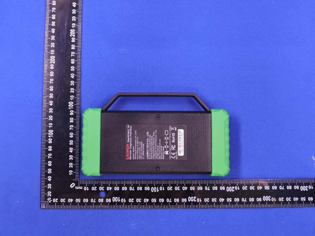
XUJS4006
Sep 04, 2026Remote Diagnosis Interface
Equipment Class
DTS - Digital Transmission SystemXUJEVT511S
Jul 09, 2026Battery Pack Airtightness Tester (High Voltage)
Equipment Class
DTS - Digital Transmission System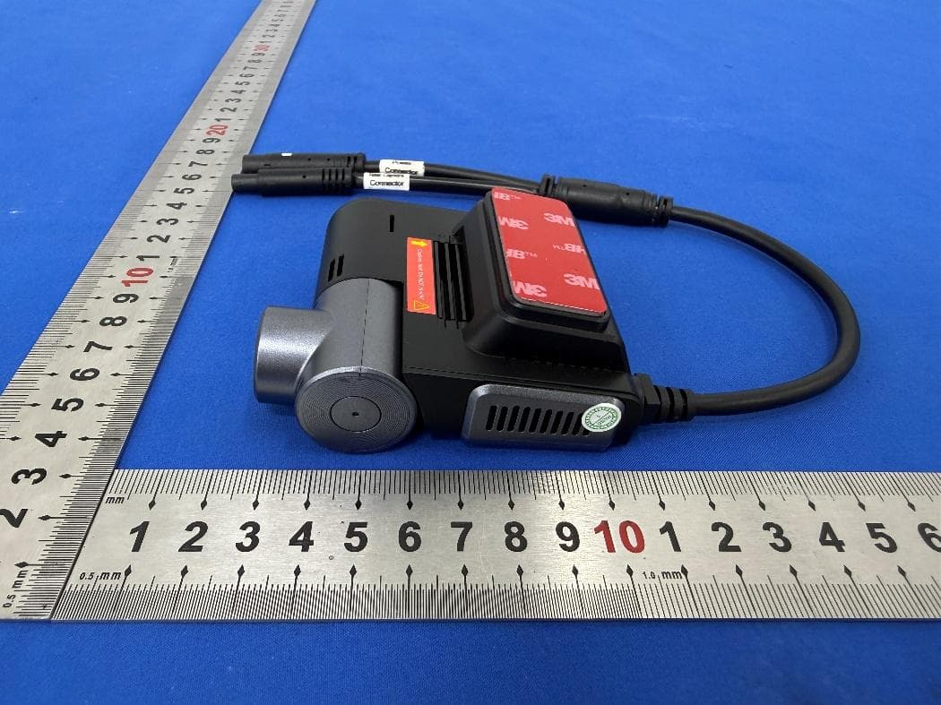
XUJG5201
Jun 26, 2026Car Sense Vision
Equipment Class
PCB - PCS Licensed Transmitter
XUJOADDPD1005A
Jun 05, 2026Automotive Diagnostic Tool
Equipment Class
NII - Unlicensed National Information Infrastructure TXXUJTSEN5S
Jan 27, 2026Programmable Universal RF Tire Pressure Sensor
Equipment Class
DSC - Part 15 Security/Remote Control Transmitter