XUJX631WAMUX-631 + Main Unit
Launch Tech Co., Ltd.
Click to zoom
Application Details
- Equipment Class
- DXX - Part 15 Low Power Communication Device Transmitter
- Date of Grant
- Aug 29, 2012
- Application Purpose
- Original Equipment
- Date of Application
- Aug 29, 2012
- Equipment Note
- X-631 + Main Unit
- Frequency Range
- 2402.00000000 - 2446.00000000
- Company
- Launch Tech Co., Ltd.
- Country
- China
Documents & Files
Document Text
Text extracted from the exhibit documents filed with the FCC. Open a document above to read the original.
Users Manual
X-631 RF User's Manual V6.00.000 2012-06-25 Trademark Information LAUNCH is a registered trademark of LAUNCH TECH. CO., LTD. (short for LAUNCH) in China and other countries. All other LAUNCH trademarks, service marks, domain names, logos, and company names referred t o in this manual are either trademarks, registered trademarks, service marks, domain names, l ogos, company names of or are otherwise the property of LAUNCH or its affiliates. In countries where any of the LAUNCH trademarks, service marks, domain names, logos and company names are not registered, LAUNCH claims o ther rights associated with unregistered trademarks, service marks, domain names, logos, and company names. Other products or company names referred to in this manual may be trademarks of their respective owners. You may not use any trademarks, service marks, domain names, logos, or company names of LAUNCH o r any third party without permission from the owner of the applicable trademarks, service m arks, domain names, logos, or c ompany names. You may contact LAUNCH b y visiting Launch at http://www.cnlaunch.com , or w riting to Launch Industrial Park, North of Wuhe Rd., Banxuegang, Longgang, Shenzhen, Guangdong, P. R. China, to request written permission to use Materials on this manual for purposes or for all other questions relating to this manual. Copyright Information Copyright © 2010 by Launch Tech Co., Ltd. All rights reserved. No part of this publication may be reproduced, stored in a retrieval system, or tra nsmitted in any form or by any means, electronic, mechanical, photocopying, recording or otherwise, without the prior written permission of LAUNCH. The information contained herein is designed only for the use of this unit. LAUNCH is not responsible for any use of this information as applied to other units. Neither LAUNCH nor its affiliates shall be liable to the purchaser of this unit or third parties for damages, losses, costs, or expenses incurred by purchaser or third parties as a result of: accident, misuse, or abuse of this unit, or unauthorized modifications, repairs, or alterations to this unit, or failure to strictly comply with LAUNCH operating and maintenance instructions. LAUNCH shall not be liable for any damages or problems arising from the use of any options or any cons umable products other than those designated as Original LAUNCH Products or LAUNCH Approved Products by LAUNCH. General Notice Other product names used herein are for identification purposes only and may be trademarks of their respective owners. LAUNCH disclaims any and all rights in those marks. 1. X-631 RF The system power supply is provided by the USB of PC. The power supply is 5.0V. The computer communicate with RF by the serial port DB9. 2. The RF connect with PC DB9 USB X-631 antenna Wire for Power supply and communicate X-631 RF 3. frequency The RF transmit have 16 frequency channels. The frequency can be selected in the 16 frequency channels. Channel List: channel frequency (MHz) channel frequency (MHz) 1 2402 9 2419 2 2404 10 2425 3 2406 11 2431 4 2408 12 2434 5 2410 13 2437 6 2412 14 2440 7 2414 15 2443 8 2416 16 2446 The state of sw1 must be cha nged when change the frequency of RF . The shorting cap is connect 2 ,3 of SW1 when the RF communicate. The 1,2 of SW1 be shorted circuit when set frequency or change frequency. The XH plug be pulled out before change the state of SW1. The XH plug be connected after change the state of SW1. After change state of SW 1, the state of SW1 is1,2 of SW1 be shorted circuit, find the module setting program, select the 2.4G module. Click the icon “read m odule frequency”, can get the frequency of RF . Select the frequency of you want, click the icon “set module frequency”, you change the frequency of RF. Only connect Wire for Power supply and communicate Power LED SW1 W ork /set frequency Receive indicator LED Transmit indicator LED shorting cap module setting program FCC ID: XUJX631WAMU This device complies with Part 15 of the FCC Rules. Operation is subject to the following two conditions: (1) this device may not cause harmful interference, and (2) this device must accept any interference received, including interference that may cause undesired operation. 2. Changes or modifications not expressly approved by the party responsible for compliance could void the user's authority to operate the equipment. NOTE: This equipment has been tested and found to comply with the limits for a Class B digital device, pursuant to Part 15 of the FCC Rules. These limits are designed to provide reasonable protection against harmful interference in a residential installation. This equipment generates uses and can radiate radio frequency energy and, if not installed and used in accordance with the instructions, may cause harmful interference to radio communications. However, there is no guarantee that interference will not occur in a particular installation. If this equipment does cause harmful interference to radio or television reception, which can be determined by turning the equipment off and on, the user is encouraged to try to correct the interference by one or more of the following measures: Reorient or relocate the receiving antenna. Increase the separation between the equipment and receiver. Connect the equipment into an outlet on a circuit different from that to which the receiver is connected. Consult the dealer or an experienced radio/TV technician for help.
Cover Letter(s)
Launch Tech Co., Ltd. August 12, 2012 To: SIEMIC, INC. 775 Montague Expressway Milpitas , CA 95035 USA Dear Sir/Madam, Re: Project and Product Certification Representative Authorization Letter We, ______ Launch Tech Co., Ltd.___hereby authorize SIEMIC, INC. to act as a Certification Body for certifying for the following project(s): Product Description: X-631+ Main Unit Model name: X-631, X-631+, X-631+D, X-631+T FCC ID: XUJX631WAMU We affirm that between SIEMIC and __ Launch Tech Co., Ltd.___, any difference in understanding, including test plan, measurement methods, applicable standards and relevant procedures and processes have been resolved prior to commencement of testing activities. Sincerely, Client’s signature: Client’s name / title: Yibing xue / Manager Contact information / address: Launch Industrial Park, North of Wuhe Rd., Banxuegang, Longgang, Shenzhen, China
Cover Letter(s)
SCS-F19: Confidentiality Request Letter Page 1 of 1 Rev 2.0 Launch Tech Co., Ltd. August 12, 2012 To: Federal Communications Commission Authorization and Evaluation Division 7435 Oakland Mills Road Columbia, MD Confidentiality Request regarding application for certification of FCC ID: XUJX631WAMU We hereby request confidential treatment of information accompanying this application as outlined below: - Block Diagram - Operational Description - Schematic The above materials contain trade secrets and proprietary information not customarily released to the public. The public disclosure of these materials may be harmful to the applicant and provide unjustified benefits to its competitors. The applicant understands that pursuant to Section 0.457 & 0.459 of the Rules, disclosure of this application and all accompanying documentation will not be made before the date of the Grant for this application. Sincerely, Client’s signature: Client’s name / title: Yibing xue / Manager Contact information / address: Launch Industrial Park, North of Wuhe Rd., Banxuegang, Longgang, Shenzhen, China
ID Label/Location Info
FCC Certification label Sample FCC ID: XUJX631WAMU This device complies with Part 15 of the FCC Rules. Operation is subject to the following two conditions: (1) This device may not cause harmful interference, and (2) This device must accept any interference received, including interference that may cause undesired operation.
ID Label/Location Info
FCC Certification Label Location Sample Label location
Internal Photos
Antenna
Test Report
Page 1 of 57 FCC ID: XUJX631WAMU ACCURATE TECHNOLOGY CO. LTD REPORT NO. ATE20120994 FCC CERTIFICATION On Behalf of Launch Tech Co., Ltd. X-631+ Main Unit Model No.: X-631, X-631+, X-631+D, X-631+T FCC ID: XUJX631WAMU Prepared for : Launch Tech Co., Ltd. Address : Launch Industrial Park, North Wuhe Avenue, Banxuegang Industrial Park, Longgang District, Shenzhen, China Prepared by : ACCURATE TECHNOLOGY CO. LTD Address : F1, Bldg. A, Changyuan New Material Port, Keyuan Rd. Science & Industry Park, Nanshan, Shenzhen, Guangdong P.R. China Tel: (0755) 26503290 Fax: (0755) 26503396 Report Number : ATE20120994 Date of Test : August 1- 10, 2012 Date of Report : August 10, 2012 Page 2 of 57 FCC ID: XUJX631WAMU ACCURATE TECHNOLOGY CO. LTD REPORT NO. ATE20120994 TABLE OF CONTENTS Description Page Test Report Certification 1. GENERAL INFORMATION .......................................................................................................... 4 1.1. Description of Device (EUT)....................................................................................................................4 1.2. Description of Test Facility ......................................................................................................................4 1.3. Measurement Uncertainty.........................................................................................................................5 2. MEASURING DEVICE AND TEST EQUIPMENT ..................................................................... 6 3. SUMMARY OF TEST RESULTS................................................................................................... 7 4. FUNDAMENTAL AND HARMONICS RADIATED EMISSION FOR SECTION 15.249(A) 8 4.1. Block Diagram of Test Setup....................................................................................................................8 4.2. The Emission Limit ..................................................................................................................................9 4.3. Configuration of EUT on Measurement ...................................................................................................9 4.4. Operating Condition of EUT ....................................................................................................................9 4.5. Test Procedure ........................................................................................................................................10 4.6. The Field Strength of Radiation Emission Measurement Results ..........................................................11 5. SPURIOUS RADIATED EMISSION FOR SECTION 15.249(D) ............................................. 14 5.1. Block Diagram of Test Setup..................................................................................................................14 5.2. The Emission Limit For Section 15.249(d) ............................................................................................15 5.3. EUT Configuration on Measurement .....................................................................................................15 5.4. Operating Condition of EUT ..................................................................................................................16 5.5. Test Procedure ........................................................................................................................................16 5.6. The Emission Measurement Result ........................................................................................................17 6. BAND EDGES ................................................................................................................................. 20 6.1. The Requirement ....................................................................................................................................20 6.2. EUT Configuration on Measurement .....................................................................................................20 6.3. Operating Condition of EUT ..................................................................................................................20 6.4. Test Procedure ........................................................................................................................................20 6.5. The Measurement Result ........................................................................................................................21 7. AC POWER LINE CONDUCTED EMISSION FOR FCC PART 15 SECTION 15.207(A) .. 23 7.1. Block Diagram of Test Setup..................................................................................................................23 7.2. The Emission Limit ................................................................................................................................23 7.3. Configuration of EUT on Measurement .................................................................................................24 7.4. Operating Condition of EUT ..................................................................................................................24 7.5. Test Procedure ........................................................................................................................................24 7.6. Power Line Conducted Emission Measurement Results ........................................................................25 8. ANTENNA REQUIREMENT........................................................................................................ 26 8.1. The Requirement ....................................................................................................................................26 8.2. Antenna Construction .............................................................................................................................26 Page 3 of 57 FCC ID: XUJX631WAMU ACCURATE TECHNOLOGY CO. LTD REPORT NO. ATE20120994 Test Report Certification…
Text truncated - open the document above for the full version.
Test Setup Photos
Conducted emissions test Radiated emissions test < 30MHz Radiated emissions test 30MHz- 1GHz Radiated emissions test > 1GHz
Contact Information
Applicant
Ivy Zhong(Manager)
Test Firm
Accurate Technology Co., Ltd.Sean Liu
Technical Specifications
| # | Rule Parts | Frequency Range | Power Output |
|---|---|---|---|
| 1 | 15C | 2.40 GHz - 2.45 GHz | - |
Other Applications from Launch Tech Co., Ltd.
XUJOADDPD1303A
Sep 17, 2026Automotive Diagnostic Tool
Equipment Class
DTS - Digital Transmission System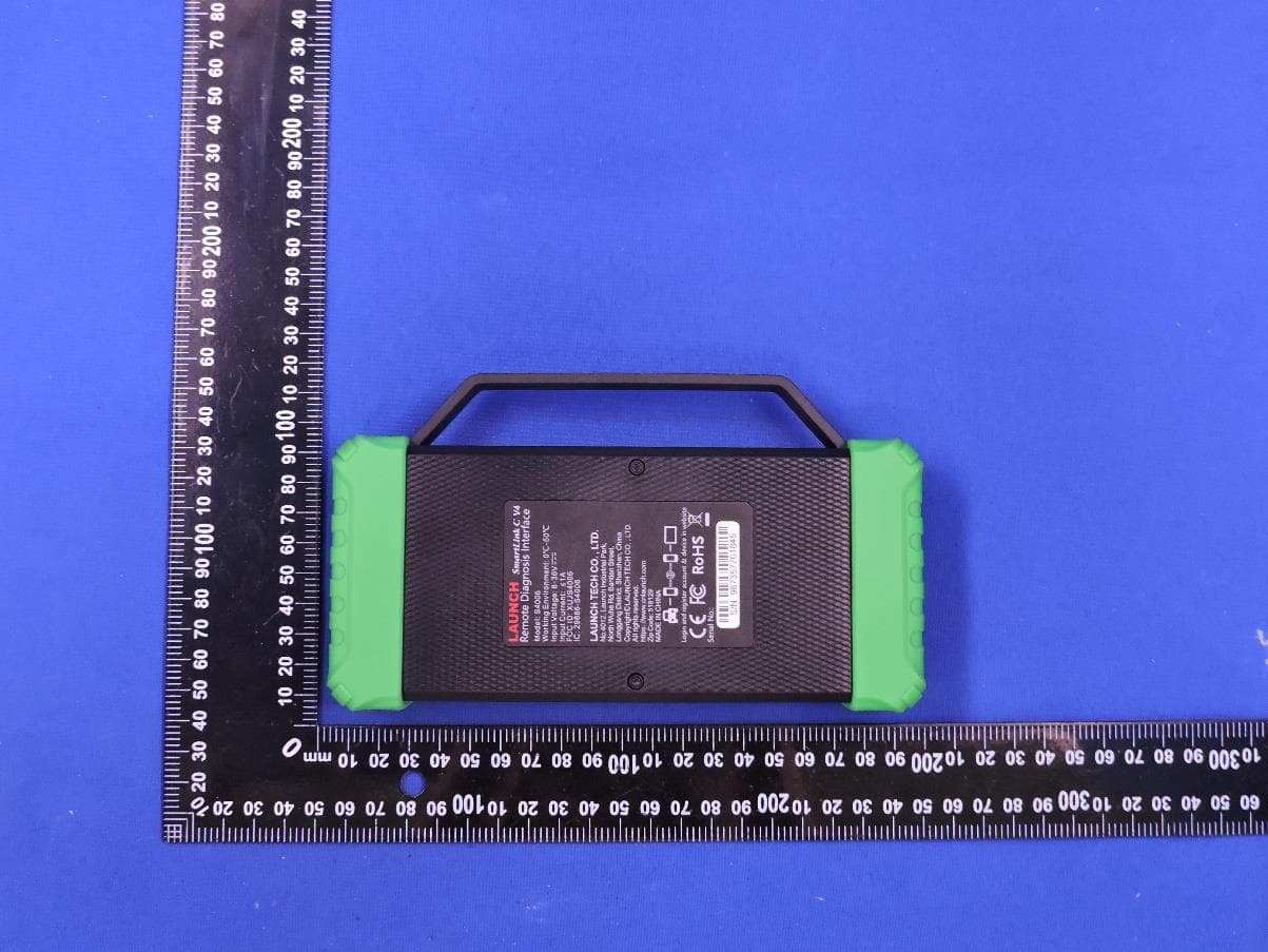
XUJS4006
Sep 04, 2026Remote Diagnosis Interface
Equipment Class
DTS - Digital Transmission SystemXUJEVT511S
Jul 09, 2026Battery Pack Airtightness Tester (High Voltage)
Equipment Class
DTS - Digital Transmission System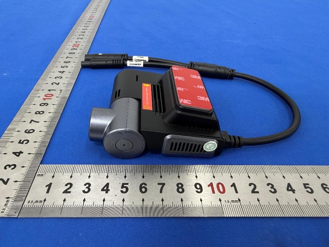
XUJG5201
Jun 26, 2026Car Sense Vision
Equipment Class
PCB - PCS Licensed Transmitter
XUJOADDPD1005A
Jun 05, 2026Automotive Diagnostic Tool
Equipment Class
NII - Unlicensed National Information Infrastructure TX