XVD40019Atticat Remote Transmitter
Concept Engineering, Inc.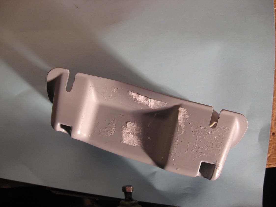
Click to zoom
Application Details
- Equipment Class
- DSC - Part 15 Security/Remote Control Transmitter
- Date of Grant
- May 16, 2010
- Application Purpose
- Original Equipment
- Date of Application
- May 16, 2010
- Equipment Note
- Atticat Remote Transmitter
- Frequency Range
- 315.00000000 - 315.00000000
- Company
- Concept Engineering, Inc.
- Country
- United States
Documents & Files
Document Text
Text extracted from the exhibit documents filed with the FCC. Open a document above to read the original.
Users Manual
1 OWNERS MANUAL ® 2 Introduction and AttiCat ® System Overview . . . . . . . . . . . . . . . . . . . . . . . . . . . . . . . . . . . . . . . .3 System Safety Features . . . . . . . . . . . . . . . . . . . . . . . . . . . . . . . . . . . . . . . . . . . . . . . . . . . . . . . . . . .4 Specifications . . . . . . . . . . . . . . . . . . . . . . . . . . . . . . . . . . . . . . . . . . . . . . . . . . . . . . . . . . . . . . . . . . .5 Choosing an Extension Cord and Using a Generator . . . . . . . . . . . . . . . . . . . . . . . . . . . . . . . . .6 Glossary . . . . . . . . . . . . . . . . . . . . . . . . . . . . . . . . . . . . . . . . . . . . . . . . . . . . . . . . . . . . . . . . . . . . . . .7 Installation Instructions Required Installation Materials . . . . . . . . . . . . . . . . . . . . . . . . . . . . . . . . . . . . . . . . . . . . . .8 Personal Protective Equipment . . . . . . . . . . . . . . . . . . . . . . . . . . . . . . . . . . . . . . . . . . . . . 8 Job Preparation . . . . . . . . . . . . . . . . . . . . . . . . . . . . . . . . . . . . . . . . . . . . . . . . . . . . . . . . . . 8 How to Install . . . . . . . . . . . . . . . . . . . . . . . . . . . . . . . . . . . . . . . . . . . . . . . . . . . . . . . . . . . .9 Maintenance Inspections Visual Inspection-External . . . . . . . . . . . . . . . . . . . . . . . . . . . . . . . . . . . . . . . . . . . . . . . . .10 Visual Inspection-Internal . . . . . . . . . . . . . . . . . . . . . . . . . . . . . . . . . . . . . . . . . . . . . . . . . .12 Operational Inspection . . . . . . . . . . . . . . . . . . . . . . . . . . . . . . . . . . . . . . . . . . . . . . . . . . . .13 Troubleshooting Guide . . . . . . . . . . . . . . . . . . . . . . . . . . . . . . . . . . . . . . . . . . . . . . . . . . . . . . . . . . .15 TABLE OF CONTENTS 3 1 MACHINE3 BAGS OF INSULATION2 HOSE INTRODUCTION SYSTEM OVERVIEW This manual is provided with the AttiCat ® Expanding Blown-in Insulation System developed by Owens Corning . This document is to be used to understand the system and to assist in the diagnosis and resolution of minor machine problems . The AttiCat ® Expanding Blown-in Insulation System consists of: 1) a blowing machine, 2) the hose, and 3) the bags of expanding loosefill insulation . The AttiCat ® blowing machine consists of the feeder and the base . The feeder is the portion of the system where the operator inserts the insulation; a gravity feed guides the insulation down onto the agitator bars in the base . Paddles on the rotating agitators break apart the insulation into smaller pieces . Insulation flows through the agitators and into the revolving valve, and is then blown into the hose by the blower . The entire path - from agitators through the hose - is required to properly condition the insulation for use in the attic . The hose is made up of two or three sections . Clamps are used to attach the sections together . The hose is attached to the base of the machine by a twist-on coupling . The attic end of the hose has a wireless remote control unit to start and stop the flow of insulation . The system is completed by the bags of the loosefill blown-in insulation product . Each of the parts is integral to the proper operation and quality of the blown-in insulation process . 4 FEEDERThe feeder is designed to enclose the insulation hopper to protect against injury by prohibiting easy access to the agitator bars within the base unit while the machine is running . The machine will not run if the feeder is not attached . This further protects the operator from the moving agitator bars and possible injury . AUTOCUTTER The AUTOCUTTER assembly completely encloses a standard utility knife blade . A blade guard on the inside of the feeder protects users from any cutting injuries . CENTER OF GRAVITY Most of the machine’s mass is concentrated in the lower unit, creating a very stable machine despite its height . (CAUTION: The base unit should be lifted by two people .) The center of gravity also enables the machine to be easily tipped slightly and wheeled around like a dolly by one person . SYSTEM SAFETY FEATURES 5 PRODUCTION RATEApproximately 7 pounds/minute, or 4-5 minutes/Bag HOSE DIAMETER21/2" ELECTRIC115 VAC 60HTZ requires one (1) 15 amp circuit to operate WEIGHT141 lbs Machine only 206 lbs shipping SPECIFICATIONS IMPORTANT NOTE: Use only AttiCat ® Blown-in PINK Fiberglas ™ Insulation. Other Materials May Damage the Machine and Void the Warranty 36” 571/4” 32” 2 31/4” FEEDER26 LBS BASE115 LBS 6 GENERATORS AND EXTENSION CORDS Your AttiCat ® machine will operate on power from a commercial-sized generator . No household generators may be used due to the high inrush requirements of the AttiCat ® machine . Also, generators made by Honda, Yamaha, Coleman and Generac are not recommended. While they are of high quality, these generators do not have the inrush protection devices necessary to start the AttiCat ® machine and protect the generator . The start-up requirement for the AttiCat ® machine is 2000 watts; normal operating requirement is 1600 watts . We recommend a generator of not less than 3000 watts, 115 VAC . In addition, the AttiCat ® Manufacturer recommends generators with a 50% power boost feature that aids the generator in high current startups . Running additional equipment from the same generator means you will need to know the total electrical requirements before selecting the correct size of generator . For details on selecting and purchasing a generator, please call 1-800-GET PINK ™ . An input line reactor will protect the AttiCat ® electronics from transient overvoltage conditions and harmful harmonic distortions (over 10%) which are common problems with electronic generators . If you plan to power the AttiCat ® machine from a generator other than as specified by the AttiCat ® manufacturer, contact the AttiCat ® manufacturer to purchase the input line reactor . This particular line reactor is made specifically for machines utilizing a…
Text truncated - open the document above for the full version.
Cover Letter(s)
February 27, 2010 American Telecommunications Certification Body, Inc. 6731 Whittier Avenue Suite C110 McLean, VA 22101 To Whom It May Concern: Please be advised that Concept Engineering, Inc. authorizes Washington Laboratories, Ltd. to act on our behalf, until otherwise notified, for applications submitted to American Telecommunications Certification Body, Inc. (ATCB). The following personnel of Washington Laboratories, Ltd. Are authorized: • Michael F. Violette, President • Steven D. Koster, EMC Operations Manager We certify that we are not subject to denial of federal benefits, that includes FCC benefits, pursuant to Section 5301 of the Anti-Drug Abuse ACT of 1988, U.S.C. 862. Further, no party, as defined in 47 CFR 1.2002(b), to the application is subject to denial of federal benefits, that includes FCC benefits. Thank you for your attention to this matter. Regards, Christopher M. Relyea President
Cover Letter(s)
February 27, 2010 American Telecommunications Certification Body, Inc. 6731 Whittier Avenue Suite C110 McLean, VA 22101 RE: Certification Application FCC ID: XVD40019 Please be advised that under the provision of 47 CFR 0.457 and 0.459 the following exhibits are to be held confidential on behalf of Concept Engineering, Inc.: • Schematics • Operational Description • Example: Block Diagram The application contains technical information that Concept Engineering, Inc. deems to be trade secrets and proprietary. If made public, the information might be used to the disadvantage of the applicant in the market place. Thank you for your attention to this matter. Regards, Christopher M. Relyea President
Cover Letter(s)
May 4, 2010 Federal Communications Commission c/o American Telecommunications Certification Body, Inc. 6731 Whittier Avenue Suite C110 McLean, VA 22101 RE: Certification Application FCC ID: XVD40019 15.19 Statement To whom it may concern, Please find attachedto this letterphotos of the device for which we are seeking certification. As the device is intended to be used, it is attached to the end of a 2”or 2- 1/2”diameter hose and it is used to blow fiberglass insulation into attic spaces. Typically, this transmitter is being used in the attic of a home and the insulationblowing machineis located outside the home. The hose is 100 to 150 feet in length and is very inflexible. Consequently, the hose, with the transmitter attached is typically dragged though the construction site as it is deloyed and stored. Thissubjects the transmitter to substantive abue. The transmitter enclosure was made relativelysmall and tapered to facilitate pulling though constuction sites without snagging onobstructions and damaging the transmitter.Additionally, the identification labelingis located in a recess for protection. Unfortunately the 15.19 statement will not fit on the label. Any additional labeling that we add may not survive when the product is in use, and therefore we request a waiver from placing the 15.19 statement on this transmitter. We will,however;prominently place the statement in the user manual. Thank you foryour attention to this matter. Regards, Christopher M. Relyea President
External Photos
External Photos ©2008 Washington Laboratories, Ltd FCC ID: XVD40019 External Photos ©2008 Washington Laboratories, Ltd FCC ID: XVD40019 External Photos ©2008 Washington Laboratories, Ltd FCC ID: XVD40019 External Photos ©2008 Washington Laboratories, Ltd FCC ID: XVD40019 External Photos ©2008 Washington Laboratories, Ltd FCC ID: XVD40019
ID Label/Location Info
PRINT COLORSWHITEPMS 485 15% BLACK BLACK DIE LINES DIE CUT DIMENSIONS ARTWORK PART # REVISION NOTES DAT E 30170 Dec 16, 2009 3 3777 BUSINESS PARK DR SUITE A COLUMBUS OH 43204 LABEL FOR REMOTE HOUSING PART # 30300 SECOND SURFACE SCREEN PRINTED ON .010” VELVET LEXAN 8A35 SEE CAD DRAWING FOR PART 30170 “REMOTE LABEL” FOR DIE CUT SPECS PERMANENT PRESURE SENSITIVE ADHESIVE BACK SIDE **GRAY TO MATCH MOLDED PLASTIC PART # 30300** ® 315 Mhz FCC ID: XVD40019 PN: 30170
Internal Photos
Internal photos ©2008 Washington Laboratories, Ltd FCC ID: XVD40019 Internal photos ©2008 Washington Laboratories, Ltd FCC ID: XVD40019 Internal photos ©2008 Washington Laboratories, Ltd FCC ID: XVD40019 Internal photos ©2008 Washington Laboratories, Ltd FCC ID: XVD40019
Test Report
Document 10770-01, Rev. 0 FCC ID: XVD40019 IC ID: TBD FCC and IC Certification Test Report Washington Laboratories, Ltd April 2010 FCC & Industry Canada Certification Test Report for Concept Engineering Inc. FCC ID: XVD40019 IC ID: TBD April 15, 2010 Prepared for: Concept Engineering Inc. 3777 Business Park Drive - Suite A Columbus, OH, 43204 Prepared By: Washington Laboratories, Ltd. 7560 Lindbergh Drive Gaithersburg, Maryland 20879 Prepared By: Washington Laboratories, Ltd. 7560 Lindbergh Drive Gaithersburg, Maryland 20879 Testing Certificate 2675.01 FCC & IC Certification Test Report Document 10770-01, Rev. 0 FCC ID: XVD40019 IC ID: TBD FCC and IC Certification Test Report Washington Laboratories, Ltd April 2010 FCC & Industry Canada Certification Test Report for the Concept Engineering Inc. Atticat Remote Transmitter FCC ID: XVD40019 IC ID: TBD April 29, 2010 WLL JOB# 10770 Prepared by: James Ritter EMC Compliance Engineer Reviewed by: Steven D. Koster EMC Operations Manager Document 10770-01, Rev. 0 FCC ID: XVD40019 IC ID: TBD FCC and IC Certification Test Report Washington Laboratories, Ltd April 2010 ii Abstract This report has been prepared on behalf of Concept Engineering Inc. to support the attached Application for Equipment Authorization. The test report and application are submitted for a Periodic Intentional Radiator under Part 15.231 of the FCC Rules and Regulations and Spectrum Management and Telecommunications Policy RSS-210 issue 7 of Industry Canada. This Federal Communication Commission (FCC) Certification Test Report documents the test configuration and test results for a Concept Engineering Inc. Atticat Remote Transmitter. Testing was performed on an Open Area Test Site (OATS) of Washington Laboratories, Ltd, 7560 Lindbergh Drive, Gaithersburg, MD 20879. Site description and site attenuation data have been placed on file with the FCC's Sampling and Measurements Branch at the FCC laboratory in Columbia, MD. The Industry Canada OATS numbers are 3035A-1 and 3035A-2 for Washington Laboratories, Ltd. Site 1 and Site 2, respectively. Washington Laboratories, Ltd. has been accepted by the FCC and approved by the American Association for Laboratory Accreditation (A2LA) under Certificate 2675.01 as an independent FCC test laboratory. The Concept Engineering Inc. Atticat Remote Transmitter complies with the limits for a Periodic Intentional Radiator device under FCC Part 15.231 and Industry Canada RSS- 210issue 7. Document 10770-01, Rev. 0 FCC ID: XVD40019 IC ID: TBD FCC and IC Certification Test Report Washington Laboratories, Ltd April 2010 iii Table of Contents Abstract ................................................................................................ii 1 Introduction..............................................................................................................1 1.1 Compliance Statement ........................................................................................ 1 1.2 Test Scope ........................................................................................................... 1 1.3 Contract Information........................................................................................... 1 1.4 Test Dates ........................................................................................................... 1 1.5 Test and Support Personnel ................................................................................ 1 2 Equipment Under Test .............................................................................................2 2.1 EUT Identification & Description ...................................................................... 2 2.2 Test Configuration .............................................................................................. 2 2.3 Testing Algorithm............................................................................................... 2 2.4 Test Location ...................................................................................................... 2 2.5 Measurements ..................................................................................................... 3 2.5.1 References................................................................................................... 3 2.6 Measurement Uncertainty................................................................................... 3 3 Test Equipment ........................................................................................................5 4 Test Results ..............................................................................................................6 4.1 Transmission Cessation from Time-of-Release.................................................. 6 4.2 Occupied Bandwidth: (FCC Part §2.1049) ......................................................... 7 4.3 Radiated Spurious Emissions.............................................................................. 8 4.3.1 Test Procedure ............................................................................................ 8 List of Tables Table 1. Device Summary................................................................................................... 2 Table 2: Expanded Uncertainty List ................................................................................... 4 Table 3: Test Equipment List............................................................................................. 5 Table 4. Occupied Bandwidth Results................................................................................ 8 Table 5. Radiated Emissions Test Data, 315 MHz, Unit On side.................................... 10 Table 6. Radiated Emissions Test Data, 315 MHz, Unit Flat........................................... 11 Table 7. Radiated Emissions Test Data, 315 MHz, Unit Upright .................................... 12 List of Figures Figure 1. Time Period: Release to Termination of Transmission......................................…
Text truncated - open the document above for the full version.
Test Setup Photos
Test Setup Photos ©2008 Washington Laboratories, Ltd Test Setup Photos ©2008 Washington Laboratories, Ltd Test Setup Photos ©2008 Washington Laboratories, Ltd
Contact Information
Applicant
Christopher Martin Relyea(President)
Technical Contact
Washington LabsSteven Koster
[email protected]301-216-1500
7560 Lindbergh Drive · Gaithersburg, Maryland · United States
Test Firm
Washington Laboratories, Ltd.Steve Koster
Technical Specifications
| # | Rule Parts | Frequency Range | Power Output |
|---|---|---|---|
| 1 | 15.231 | 315 MHz - 315 MHz | - |