XVZGITCPJ318Cellular Data Terminal Equipment
Kobelco Construction Machinery Co., Ltd.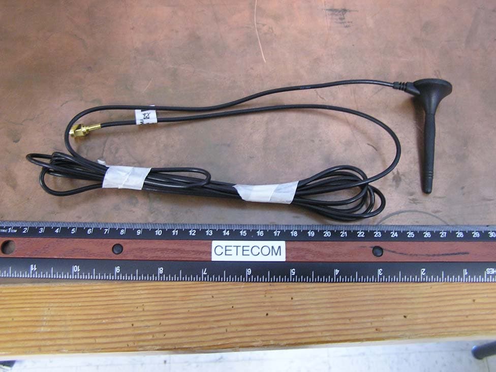
Click to zoom
Application Details
- Equipment Class
- PCB - PCS Licensed Transmitter
- Date of Grant
- Dec 22, 2009
- Application Purpose
- Original Equipment
- Date of Application
- Dec 22, 2009
- Equipment Note
- Cellular Data Terminal Equipment
- Frequency Range
- 1852.40000000 - 1907.60000000
- Country
- Japan
Documents & Files
Document Text
Text extracted from the exhibit documents filed with the FCC. Open a document above to read the original.
Users Manual
Technical description for Global IT Controller model number JD22E00004F1 1.The system summary of Global IT Controller JD22E00004F1 This device (called "GITC") calculates the operation information of the crane, and it is a controller having a function to transmit a message to WEB server after having saved it temporarily. In addition, it is equipped with the GPS function. The system summary in Fig.1. During the control of the crane, an operator does not operate this GITC directly at all. GITC has no buttons which a operator operates directly. By communication between the controller or the receipt electric wave signal from the outside, it functions entirely. But the operation of GITC has only a monitoring function for the operation of the crane without influence entirely. The trouble of GITC does not influence the operation of the crane. . This device communicates in the following condition during crane driving for the Web server. * At the time of the trouble outbreak of the crane again at the time of trouble cancellation * When serious operation about security occurred operationally * When GITC transmits accumulation data for 1st regularly (By night) * When there was data demand from the WEB server. Fig.1. The system summary of Crawler Crane GITC System 2.The installation of the device This device is installed near the driver's seat of the cranes cabin. Figure of placement of the operator's seat is just what to show it in Fig.2,Fig.3. The GITC is connected to an Load Safety Device (LSD) installed on a crane by a RS232C communications cable. The power supply is connected to the battery of the crane directly and can transmit the data which I saved by the receipt from the outside even if a crane is not switched on. In addition, the built-in battery is not equipped with GITC. GPS Antenna Cable 3G/GSM Antenna Cable Communication to LSD and battery supply harness The details of the installation of the GITC with some cable. GITC (JD22E00004F1) M6×4 Adapter Cable Fig.3 Fig.2. The installation of GITC Fig.3. The installation of GITC (Details) Load Safety Device GITC About 300 ~ 400mm Crane Cabin Front 3.FCC statements 3.1. NOTICE: This device complies with Part 15 of the FCC Rules and with RSS-210 of Industry Canada. Operation is subject to the following two conditions: (1) this device may not cause harmful interference, and (2) this device must accept any interference received, including interference that may cause undesired operation. 3.2. NOTICE: Changes or modifications made to this equipment not expressly approved by KOBELCO CRANES CO.,LTD. may void the FCC authorization to operate this equipment. 3.3. NOTE: This equipment has been tested and found to comply with the limits for a Class B digital device, pursuant to Part 15 of the FCC Rules. These limits are designed to provide reasonable protection against harmful interference in a residential installation. This equipment generates, uses and can radiate radio frequency energy and, if not installed and used in accordance with the instructions, may cause harmful interference to radio communications. However, there is no guarantee that interference will not occur in a particular installation. If this equipment does cause harmful interference to radio or television reception, which can be determined by turning the equipment off and on, the user is encouraged to try to correct the interference by one or more of the following measures: - Reorient or relocate the receiving antenna. - Increase the separation between the equipment and receiver. - Connect the equipment into an outlet on a circuit different from that to which the receiver is connected. - Consult the dealer or an experienced radio/TV technician for help. 3.4. RF Exposure: Radiofrequency radiation exposure Information: This equipment complies with FCC radiation exposure limits set forth for an uncontrolled environment. This equipment should be installed and operated with minimum distance of 20 cm between the radiator and your body. This transmitter must not be co-located or operating in conjunction with any other antenna or transmitter.
External Photos
External Photos
RF Exposure Info
FCC-ID XVZGITCPJ318 IC-ID (Industry Canada) 8711A-GITCPJ318 PREDICTION OF MPE AT A GIVEN DISTANCE Calculations can be made to predict RF field strength and power density levels around typical RF sources using the general equations (3) and (4) on page 19 of the following FCC document: “OET Bulletin 65, Edition 97-01 - Evaluating Compliance with FCC Guidelines for Human Exposure to Radio frequency Electromagnetic Fields”. These equations are generally accurate in the far field of an antenna but will over predict power density in the near field, where they could be used for making a “worst case” prediction. S = PG/4πR 2 (3) Where S = power density (in appropriate units, e.g. mW/cm 2 ) P = power input to the antenna (in appropriate units e.g. mW) G = power gain of the antenna in the direction of interest relative to the isotropic radiator R = distance to the center of radiation of the antenna (appropriate units e.g. cm) or, S = EIRP/4πR 2 (4) Where EIRP = Equivalent Isotropically radiated power General Limits: §1.1307 Cellular Radiotelephone Service (subpart H of part 22) Non-building-mounted antennas: height above ground level to lowest point of antenna < 10 m and total power of all channels > 1000 W ERP (1640 W EIRP) §1.1307 Personal Communications Services (part 24) Broadband PCS (subpart E): non-building-mounted antennas: height above ground level to lowest point of antenna < 10 m and total power of all channels > 2000 W ERP (3280 W EIRP) §1.1310 LIMITS FOR MAXIMUM PERMISSIBLE EXPOSURE (MPE) (B) Limits for General Population/Uncontrolled Exposure 300–1500 MHz: f/1500 mW/cm² 1500–100,000 MHz: 1.0 mW/cm² §2.1091 No routine evaluation required when the device ...operate at frequencies of 1.5 GHz or below and their effective radiated power (ERP) is 1.5 watts or more, or if they operate at frequencies above 1.5 GHz and their ERP is 3 watts or more. FCC-ID XVZGITCPJ318 IC-ID (Industry Canada) 8711A-GITCPJ318 §24.232 (a) Base stations are limited to 1640 watts peak equivalent isotropically radiated power (e.i.r.p.) with an antenna height up to 300 meters HAAT. b) Mobile/portable stations are limited to 2 watts e.i.r.p. peak power, ... §22.913 (a) Maximum ERP. The effective radiated power (ERP) of base transmitters and cellular repeaters must not exceed 500 Watts. The ERP of mobile transmitters and auxiliary test transmitters must not exceed 7 Watts. The table below is excerpted from Table 1B of 47 CFR 1.1310 titled “Limits for Maximum Permissible Exposure (MPE), Limits for General Population/Uncontrolled Exposure” Frequency Range (MHz) Power Density (mW/cm 2 ) 300 -1500 f/1500 1500 - 100000 1.0 Prediction for Part 22 Maximum radiated power EIRP: 32.434 dBm (1751.46mW) @ 848.8MHz Lowest limit for 850 MHz fixed operations (@20cm) where no routine evaluation is required is § 1.1310: (f/1500)mW/cm 2 =0.5659 mW/cm 2 Calculated at distance of 20cm for reference antenna: Power density = 1751.46 / (4 x pi x 20 2 ) = 0.3486 mW/cm 2 Result: Configuration complies with rules as power density is below MPE limit. Prediction for Part 24 Maximum radiated power EIRP: 29.722 dBm (937.99 mW) @1909.8 MHz Lowest limit for 1900 MHz fixed operations (@20cm) where no routine evaluation is required is § 1.1310 : 1 mW/cm 2 Calculated at distance of 20cm: Power density = 937.99 / (4 x pi x 20 2 ) = 0.1867 mW/cm 2 Result: Configuration complies with rules as power density is below MPE limit. FCC-ID XVZGITCPJ318 IC-ID (Industry Canada) 8711A-GITCPJ318 Date: 2009-12-10 Name: Josie Sabado Title: EMC Project Engineer Company: Cetecom Inc. Address: 411 Dixon Landing Rd, Milpitas, CA 95035, USA Phone: +1 408 586 6230 Email: [email protected]
Test Report
7 layers AG Aufsichtsratsvorsitzenderh Registergerichth registered in: Borsigstrasse 11 Chairman of the Supervisory Board: Düsseldorf, HRB 44096 40880 Ratingen, Germany Markus Becker USt-IdNr h VAT Nr: Phone: +49 (0) 2102 749 0 Vorstandh Board: DE 203159652 Fax: +49 (0) 2102 749 350 Dr. Hans-Jürgen Meckelburg www.7Layers.com René Schildknecht InterLab is a registered trademark of 7 layers AG FCC Measurement/Technical Report on GSM/UMTS module Siemens Cellular Engine HC25 Report Reference: MDE_Siem_0605_FCCb Test Laboratory: 7 layers AG Borsigstrasse 11 40880 Ratingen Germany email: [email protected] DAT-P-192/99-01 Note: The following test results relate only to the devices specified in this document. This report shall not be reproduced in parts without the written approval of the testing laboratory. Test report Reference: MDE_Siem_0605_FCCb Page 2 of 67 Table of Contents 0 Summary 3 0.1 Technical Report Summary 3 0.2 Measurement Summary 4 1 Administrative Data 6 1.1 Testing Laboratory 6 1.2 Project Data 6 1.3 Applicant Data 6 1.4 Manufacturer Data 6 2 Testobject Data 7 2.1 General EUT Description 7 2.2 EUT Main components 8 2.3 Ancillary Equipment 8 2.4 EUT Setups 8 2.5 Operating Modes 9 3 Test Results 10 3.1 RF Power Output 10 3.2 Frequency stability 14 3.3 Spurious emissions at antenna terminals 20 3.4 Field strength of spurious radiation 24 3.5 Emission and Occupied Bandwidth 28 3.6 Band edge compliance 32 4 Test Equipment 35 5 Photo Report 38 6 Setup Drawings 42 7 Annex 44 Measurement Plots Test report Reference: MDE_Siem_0605_FCCb Page 3 of 67 0 Summary 0.1 Technical Report Summary Type of Authorization Certification for a GSM cellular radiotelephone device Applicable FCC Rules Prepared in accordance with the requirements of FCC Rules and Regulations as listed in 47 CFR Ch.1 Parts 0 to 19 and Parts 20 to 69 (10-1-06 Edition). The following subparts are applicable to the results in this test report. Part 2 Subpart J - Equipment Authorization Procedures, Certification § 2.1046 Measurement required: RF power output § 2.1049 Measurement required: Occupied bandwidth § 2.1051 Measurement required: Spurious emissions at antenna terminals § 2.1053 Measurement required: Field strength of spurious radiation § 2.1055 Measurement required: Frequency stability § 2.1057 Frequency spectrum to be investigated Part 22 Subpart C – Operational and Technical Requirements § 22.355 Frequency tolerance Subpart H – Cellular Radiotelephone Service § 22.913 Effective radiated power limits § 22.917 Emission limitations for cellular equipment Summary Test The EUT complied with all performed tests as listed in chapter 0.2 Measurement Summary. Test report Reference: MDE_Siem_0605_FCCb Page 4 of 67 0.2 Measurement Summary RF Power Output The measurement was performed according to FCC §2.1046 10-1-06 OP-Mode Setup Port Final Result op-mode 1 setup_a01 antenna connector passed op-mode 2 setup_a01 antenna connector passed op-mode 3 setup_a01 antenna connector passed op-mode 4 setup_a01 antenna connector passed op-mode 5 setup_a01 antenna connector passed op-mode 6 setup_a01 antenna connector passed op-mode 7 setup_a01 antenna connector passed op-mode 8 setup_a01 antenna connector passed op-mode 9 setup_a01 antenna connector passed Frequency stability The measurement was performed according to FCC §2.1055 10-1-06 OP-Mode Setup Port Final Result op-mode 2 setup_a01 antenna connector passed op-mode 5 setup_a01 antenna connector passed op-mode 8 setup_a01 antenna connector passed Spurious emissions at antenna terminals The measurement was performed according to FCC §2.1051 10-1-06 OP-Mode Setup Port Final Result op-mode 1 setup_a01 antenna connector passed op-mode 2 setup_a01 antenna connector passed op-mode 3 setup_a01 antenna connector passed op-mode 4 setup_a01 antenna connector passed op-mode 5 setup_a01 antenna connector passed op-mode 6 setup_a01 antenna connector passed op-mode 7 setup_a01 antenna connector passed op-mode 8 setup_a01 antenna connector passed op-mode 9 setup_a01 antenna connector passed Field strength of spurious radiation The measurement was performed according to FCC §2.1053 10-1-06 OP-Mode Setup Port Final Result op-mode 1 setup_a02 enclosure passed op-mode 2 setup_a02 enclosure passed op-mode 3 setup_a02 enclosure passed op-mode 4 setup_a02 enclosure passed op-mode 5 setup_a02 enclosure passed op-mode 6 setup_a02 enclosure passed op-mode 7 setup_a02 enclosure passed op-mode 8 setup_a02 enclosure passed op-mode 9 setup_a02 enclosure passed Test report Reference: MDE_Siem_0605_FCCb Page 6 of 67 1 Administrative Data 1.1 Testing Laboratory Company Name: 7 Layers AG Address Borsigstr. 11 40880 Ratingen Germany This facility has been fully described in a report submitted to the FCC and accepted under the registration number 96716 . The test facility is also accredited by the following accreditation organisation: - Deutscher Akkreditierungs Rat DAR-Registration no. DAT-P-192/99-01 Responsible for Accreditation Scope: Dipl.-Ing. Bernhard Retka Dipl.-Ing. Robert Machulec Dipl.-Ing. Thomas Hoell Report Template Version: 2006-12-18 1.2 Project Data Responsible for testing and report: Dipl.-Ing. Andreas Petz Date of Test(s): 2007-02-09 to 2007-03-02 Date of Report: 2007-03-15 1.3 Applicant Data Company Name: Siemens AG Address: Siemensdamm 50 13629 Berlin Germany Contact Person: Mr. Hussein Halawi 1.4 Manufacturer Data Company Name: please see applicant data Address: Contact Person: Test report Reference: MDE_Siem_0605_FCCb Page 7 of 67 2 Testobject Data 2.1 General EUT Description Equipment under Test: GSM/UMTS module Type Designation: Siemens Cellular Engine HC25 Kind of Device: (optional) GSM 850/900/1800/1900 + UMTS FDD I/II/V module Voltage Type: DC Nominal Voltage: 4.2 V Maximum Voltage: 4.2 V Minimum Voltage: 3.2 V General product description: The Equipment Under Test (EUT) is a GSM 850/900/1800/1900 module and supports EDGE and FDD I/II/V. The manufacturer declared that nominal voltage is equal …
Text truncated - open the document above for the full version.
Test Report
7 layers AG Aufsichtsratsvorsitzenderh Registergerichth registered in: Borsigstrasse 11 Chairman of the Supervisory Board: Düsseldorf, HRB 44096 40880 Ratingen, Germany Markus Becker USt-IdNr h VAT Nr: Phone: +49 (0) 2102 749 0 Vorstandh Board: DE 203159652 Fax: +49 (0) 2102 749 350 Dr. Hans-Jürgen Meckelburg www.7Layers.com René Schildknecht InterLab is a registered trademark of 7 layers AG FCC Measurement/Technical Report on GSM/UMTS module Siemens Cellular Engine HC25 Report Reference: MDE_Siem_0605_FCCa Test Laboratory: 7 layers AG Borsigstrasse 11 40880 Ratingen Germany email: [email protected] DAT-P-192/99-01 Note: The following test results relate only to the devices specified in this document. This report shall not be reproduced in parts without the written approval of the testing laboratory. Test report Reference: MDE_Siem_0605_FCCa Page 2 of 67 Table of Contents 0 Summary 3 0.1 Technical Report Summary 3 0.2 Measurement Summary 4 1 Administrative Data 6 1.1 Testing Laboratory 6 1.2 Project Data 6 1.3 Applicant Data 6 1.4 Manufacturer Data 6 2 Testobject Data 7 2.1 General EUT Description 7 2.2 EUT Main components 8 2.3 Ancillary Equipment 8 2.4 EUT Setups 8 2.5 Operating Modes 9 3 Test Results 10 3.1 RF Power Output 10 3.2 Frequency stability 14 3.3 Spurious emissions at antenna terminals 20 3.4 Field strength of spurious radiation 24 3.5 Emission and Occupied Bandwidth 28 3.6 Band edge compliance 32 4 Test Equipment 35 5 Photo Report 38 6 Setup Drawings 42 7 Annex 44 Measurement Plots Test report Reference: MDE_Siem_0605_FCCa Page 3 of 67 0 Summary 0.1 Technical Report Summary Type of Authorization Certification for a GSM cellular radiotelephone device Applicable FCC Rules Prepared in accordance with the requirements of FCC Rules and Regulations as listed in 47 CFR Ch.1 Parts 0 to 19 and Parts 20 to 69 (10-1-06 Edition). The following subparts are applicable to the results in this test report. Part 2 Subpart J - Equipment Authorization Procedures, Certification § 2.1046 Measurement required: RF power output § 2.1049 Measurement required: Occupied bandwidth § 2.1051 Measurement required: Spurious emissions at antenna terminals § 2.1053 Measurement required: Field strength of spurious radiation § 2.1055 Measurement required: Frequency stability § 2.1057 Frequency spectrum to be investigated Part 24 Subpart E - Broadband PCS § 24.232 Power and antenna height limits § 24.235 Frequency stability § 24.236 Field strength limits § 24.238 Emission limitations for Broadband PCS equipment Summary Test Results: The EUT complied with all performed tests as listed in chapter 0.2 Measurement Summary. Test report Reference: MDE_Siem_0605_FCCa Page 4 of 67 0.2 Measurement Summary RF Power Output The measurement was performed according to FCC §2.1046 10-1-06 OP-Mode Setup Port Final Result op-mode 1 setup_a01 antenna connector passed op-mode 2 setup_a01 antenna connector passed op-mode 3 setup_a01 antenna connector passed op-mode 4 setup_a01 antenna connector passed op-mode 5 setup_a01 antenna connector passed op-mode 6 setup_a01 antenna connector passed op-mode 7 setup_a01 antenna connector passed op-mode 8 setup_a01 antenna connector passed op-mode 9 setup_a01 antenna connector passed Frequency stability The measurement was performed according to FCC §2.1055 10-1-06 OP-Mode Setup Port Final Result op-mode 2 setup_a01 antenna connector passed op-mode 4 setup_a01 antenna connector passed op-mode 8 setup_a01 antenna connector passed Spurious emissions at antenna terminals The measurement was performed according to FCC §2.1051 10-1-06 OP-Mode Setup Port Final Result op-mode 1 setup_a01 antenna connector passed op-mode 2 setup_a01 antenna connector passed op-mode 3 setup_a01 antenna connector passed op-mode 4 setup_a01 antenna connector passed op-mode 5 setup_a01 antenna connector passed op-mode 6 setup_a01 antenna connector passed op-mode 7 setup_a01 antenna connector passed op-mode 8 setup_a01 antenna connector passed op-mode 9 setup_a01 antenna connector passed Field strength of spurious radiation The measurement was performed according to FCC §2.1053 10-1-06 OP-Mode Setup Port Final Result op-mode 1 setup_a02 enclosure passed op-mode 2 setup_a02 enclosure passed op-mode 3 setup_a02 enclosure passed op-mode 4 setup_a02 enclosure passed op-mode 5 setup_a02 enclosure passed op-mode 6 setup_a02 enclosure passed op-mode 7 setup_a02 enclosure passed op-mode 8 setup_a02 enclosure passed op-mode 9 setup_a02 enclosure passed Test report Reference: MDE_Siem_0605_FCCa Page 6 of 67 1 Administrative Data 1.1 Testing Laboratory Company Name: 7 Layers AG Address Borsigstr. 11 40880 Ratingen Germany This facility has been fully described in a report submitted to the FCC and accepted under the registration number 96716 . The test facility is also accredited by the following accreditation organisation: - Deutscher Akkreditierungs Rat DAR-Registration no. DAT-P-192/99-01 Responsible for Accreditation Scope: Dipl.-Ing. Bernhard Retka Dipl.-Ing. Robert Machulec Dipl.-Ing. Thomas Hoell Report Template Version: 2006-12-18 1.2 Project Data Responsible for testing and report: Dipl.-Ing. Andreas Petz Date of Test(s): 2007-02-09 to 2007-03-02 Date of Report: 2007-03-16 1.3 Applicant Data Company Name: Siemens AG Address: Siemensdamm 50 13629 Berlin Germany Contact Person: Mr. Hussein Halawi 1.4 Manufacturer Data Company Name: please see applicant data Address: Contact Person: Test report Reference: MDE_Siem_0605_FCCa Page 7 of 67 2 Testobject Data 2.1 General EUT Description Equipment under Test: GSM/UMTS module Type Designation: Siemens Cellular Engine HC25 Kind of Device: (optional) GSM 850/900/1800/1900 + UMTS FDD I/II/V module Voltage Type: DC Nominal Voltage: 4.2 V Maximum Voltage: 4.2 V Minimum Voltage: 3.2 V General product description: The Equipment Under Test (EUT) is a GSM 850/900/1800/1900 module and supports EDGE and FDD I/II/V. The manufacturer declared that nominal voltage is equal to maximum voltage. In P…
Text truncated - open the document above for the full version.
Test Report
7 layers AG Aufsichtsratsvorsitzenderh Registergerichth registered in: Borsigstrasse 11 Chairman of the Supervisory Board: Düsseldorf, HRB 44096 40880 Ratingen, Germany Markus Becker USt-IdNr h VAT Nr: Phone: +49 (0) 2102 749 0 Vorstandh Board: DE 203159652 Fax: +49 (0) 2102 749 350 Dr. Hans-Jürgen Meckelburg TAX No. 147/5869/0385 www.7Layers.com René Schildknecht InterLab is a registered trademark of 7 layers AG FCC Measurement/Technical Report on GSM/UMTS module Siemens Cellular Engine HC28 Report Reference: MDE_Siem_0605_FCCe Test Laboratory: 7 layers AG Borsigstrasse 11 40880 Ratingen Germany email: [email protected] DAT-P-192/99-01 Note: The following test results relate only to the devices specified in this document. This report shall not be reproduced in parts without the written approval of the testing laboratory. Test report Reference: MDE_Siem_0605_FCCe Page 2 of 32 Table of Contents 0 Summary 3 0.1 Technical Report Summary 3 0.2 Measurement Summary 4 1 Administrative Data 6 1.1 Testing Laboratory 6 1.2 Project Data 6 1.3 Applicant Data 6 1.4 Manufacturer Data 6 2 Testobject Data 7 2.1 General EUT Description 7 2.2 EUT Main components 8 2.3 Ancillary Equipment 8 2.4 EUT Setups 8 2.5 Operating Modes 9 3 Test Results 10 3.1 RF Power Output 10 3.2 Spurious emissions at antenna terminals 12 3.3 Emission and Occupied Bandwidth 15 4 Test Equipment 18 5 Photo Report 22 6 Setup Drawings 25 7 Annex 27 Measurement Plots Test report Reference: MDE_Siem_0605_FCCe Page 3 of 32 0 Summary 0.1 Technical Report Summary Type of Authorization Certification for a GSM cellular radiotelephone device Applicable FCC Rules Prepared in accordance with the requirements of FCC Rules and Regulations as listed in 47 CFR Ch.1 Parts 0 to 19 and Parts 20 to 69 (10-1-06 Edition). The following subparts are applicable to the results in this test report. Part 2 Subpart J - Equipment Authorization Procedures, Certification § 2.1046 Measurement required: RF power output § 2.1049 Measurement required: Occupied bandwidth § 2.1051 Measurement required: Spurious emissions at antenna terminals § 2.1053 Measurement required: Field strength of spurious radiation § 2.1055 Measurement required: Frequency stability § 2.1057 Frequency spectrum to be investigated Part 22 Subpart C – Operational and Technical Requirements § 22.355 Frequency tolerance Subpart H – Cellular Radiotelephone Service § 22.913 Effective radiated power limits § 22.917 Emission limitations for cellular equipment Summary Test The EUT complied with all performed tests as listed in chapter 0.2 Measurement Summary. Test report Reference: MDE_Siem_0605_FCCe Page 4 of 32 0.2 Measurement Summary RF Power Output The measurement was performed according to FCC §2.1046 10-1-06 OP-Mode Setup Port Final Result op-mode 1 setup_03 antenna connector passed op-mode 2 setup_03 antenna connector passed op-mode 3 setup_03 antenna connector passed op-mode 4 setup_03 antenna connector passed op-mode 5 setup_03 antenna connector passed op-mode 6 setup_03 antenna connector passed op-mode 7 setup_03 antenna connector passed op-mode 8 setup_03 antenna connector passed op-mode 9 setup_03 antenna connector passed op-mode 10 setup_01 antenna connector passed op-mode 11 setup_01 antenna connector passed op-mode 12 setup_01 antenna connector passed Frequency stability The measurement was performed according to FCC §2.1055 10-1-06 OP-Mode Setup Port Final Result – – – N/P Spurious emissions at antenna terminals The measurement was performed according to FCC §2.1051 10-1-06 OP-Mode Setup Port Final Result op-mode 2 setup_02 antenna connector passed op-mode 5 setup_02 antenna connector passed op-mode 8 setup_02 antenna connector passed Field strength of spurious radiation The measurement was performed according to FCC §2.1053 10-1-06 OP-Mode Setup Port Final Result – – – N/P Emission and Occupied Bandwidth The measurement was performed according to FCC §2.1049 10-1-06 OP-Modte Setup Port Final Result op-mode 2 setup_02 antenna connector passed op-mode 5 setup_02 antenna connector passed op-mode 8 setup_02 antenna connector passed Band edge compliance The measurement was performed according to FCC §2.1053 OP-Modl~ Setup Port 10-1-06 Final Result NIP NIP not performed The tests were chosen in agreement with the applicant. This module HC28 is a modification of the module HC25 (FCC 10: QIPHC25). 'layers 7 layers AG, Borsigstr. 11 40880 Ratingen, GermallY Phone +49 (0)2102 749 0 Responsible for Responsible Accreditation Scope: for Test Report: a.~ Page 5 of 32 Test report Reference: MDE_Siem_0605_FCCe Page 6 of 32 1 Administrative Data 1.1 Testing Laboratory Company Name: 7 Layers AG Address Borsigstr. 11 40880 Ratingen Germany This facility has been fully described in a report submitted to the FCC and accepted under the registration number 96716 . The test facility is also accredited by the following accreditation organisation: - Deutscher Akkreditierungs Rat DAR-Registration no. DAT-P-192/99-01 Responsible for Accreditation Scope: Dipl.-Ing. Bernhard Retka Dipl.-Ing. Robert Machulec Dipl.-Ing. Thomas Hoell Report Template Version: 2007-08-29 1.2 Project Data Responsible for testing and report: Dipl.-Ing. Andreas Petz Receipt of EUT: 2007-08-14 Date of Test(s): 2007-08-22 to 2007-09-11 Date of Report: 2007-09-17 1.3 Applicant Data Company Name: Siemens AG Address: Siemensdamm 50 13629 Berlin Germany Contact Person: Mr. Hussein Halawi 1.4 Manufacturer Data Company Name: please see applicant data Address: Contact Person: Test report Reference: MDE_Siem_0605_FCCe Page 7 of 32 2 Testobject Data 2.1 General EUT Description Equipment under Test: GSM/UMTS module Type Designation: Siemens Cellular Engine HC28 Kind of Device: (optional) GSM 850/900/1800/1900 + UMTS FDD I/II/V module Voltage Type: DC Nominal Voltage: 4.2 V Maximum Voltage: 4.2 V Minimum Voltage: 3.5 V General product description: The Equipment Under Test (EUT) is a GSM 850/900/1800/1900 module and supports EDGE and FDD I/II/V with HSD…
Text truncated - open the document above for the full version.
Test Report
7 layers AG Aufsichtsratsvorsitzenderh Registergerichth registered in: Borsigstrasse 11 Chairman of the Supervisory Board: Düsseldorf, HRB 44096 40880 Ratingen, Germany Markus Becker USt-IdNr h VAT Nr: Phone: +49 (0) 2102 749 0 Vorstandh Board: DE 203159652 Fax: +49 (0) 2102 749 350 Dr. Hans-Jürgen Meckelburg TAX No. 147/5869/0385 www.7Layers.com René Schildknecht InterLab is a registered trademark of 7 layers AG FCC Measurement/Technical Report on GSM/UMTS module Siemens Cellular Engine HC28 Report Reference: MDE_Siem_0605_FCCf Test Laboratory: 7 layers AG Borsigstrasse 11 40880 Ratingen Germany email: [email protected] DAT-P-192/99-01 Note: The following test results relate only to the devices specified in this document. This report shall not be reproduced in parts without the written approval of the testing laboratory. Test report Reference: MDE_Siem_0605_FCCf Page 2 of 40 Table of Contents 0 Summary 3 0.1 Technical Report Summary 3 0.2 Measurement Summary 4 1 Administrative Data 6 1.1 Testing Laboratory 6 1.2 Project Data 6 1.3 Applicant Data 6 1.4 Manufacturer Data 6 2 Testobject Data 7 2.1 General EUT Description 7 2.2 EUT Main components 8 2.3 Ancillary Equipment 8 2.4 EUT Setups 8 2.5 Operating Modes 9 3 Test Results 10 3.1 RF Power Output 10 3.2 Spurious emissions at antenna terminals 12 3.3 Field strength of spurious radiation 15 3.4 Emission and Occupied Bandwidth 18 3.5 Band edge compliance 21 4 Test Equipment 23 5 Photo Report 27 6 Setup Drawings 30 7 Annex 32 Measurement Plots Test report Reference: MDE_Siem_0605_FCCf Page 3 of 40 0 Summary 0.1 Technical Report Summary Type of Authorization Certification for a GSM cellular radiotelephone device Applicable FCC Rules Prepared in accordance with the requirements of FCC Rules and Regulations as listed in 47 CFR Ch.1 Parts 0 to 19 and Parts 20 to 69 (10-1-06 Edition). The following subparts are applicable to the results in this test report. Part 2 Subpart J - Equipment Authorization Procedures, Certification § 2.1046 Measurement required: RF power output § 2.1049 Measurement required: Occupied bandwidth § 2.1051 Measurement required: Spurious emissions at antenna terminals § 2.1053 Measurement required: Field strength of spurious radiation § 2.1055 Measurement required: Frequency stability § 2.1057 Frequency spectrum to be investigated Part 24 Subpart E - Broadband PCS § 24.232 Power and antenna height limits § 24.235 Frequency stability § 24.236 Field strength limits § 24.238 Emission limitations for Broadband PCS equipment Summary Test Results: The EUT complied with all performed tests as listed in chapter 0.2 Measurement Summary. Test report Reference: MDE_Siem_0605_FCCf Page 4 of 40 0.2 Measurement Summary RF Power Output The measurement was performed according to FCC §2.1046 10-1-06 OP-Mode Setup Port Final Result op-mode 1 setup_04 antenna connector passed op-mode 2 setup_04 antenna connector passed op-mode 3 setup_04 antenna connector passed op-mode 4 setup_04 antenna connector passed op-mode 5 setup_04 antenna connector passed op-mode 6 setup_04 antenna connector passed op-mode 7 setup_04 antenna connector passed op-mode 8 setup_04 antenna connector passed op-mode 9 setup_04 antenna connector passed op-mode 10 setup_02 antenna connector passed op-mode 11 setup_02 antenna connector passed op-mode 12 setup_02 antenna connector passed Frequency stability The measurement was performed according to FCC §2.1055 10-1-06 OP-Mode Setup Port Final Result – – – N/P Spurious emissions at antenna terminals The measurement was performed according to FCC §2.1051 10-1-06 OP-Mode Setup Port Final Result op-mode 2 setup_01 antenna connector passed op-mode 5 setup_01 antenna connector passed op-mode 8 setup_03 antenna connector passed Field strength of spurious radiation The measurement was performed according to FCC §2.1053 10-1-06 OP-Mode Setup Port Final Result op-mode 2 setup_05 enclosure passed op-mode 5 setup_05 enclosure passed op-mode 8 setup_05 enclosure passed ~layers Emission and Occupied Bandwidth The measurement was performed according to FCC §2.1049 10-1-06 OP-Mode Setup Port Final Result op-mode 2 setup_01 antenna connector passed op-mode 5 setup_01 an…
Text truncated - open the document above for the full version.
Contact Information
Applicant
Motohiko Mizutani(Group Manager)
Test Firm
CETECOM Inc.Meinolf Glunz
[email protected]408-586-6301
Technical Specifications
| # | Rule Parts | Frequency Range | Power Output | Emission | Tolerance |
|---|---|---|---|---|---|
| 6 | 24E | 1.85 GHz - 1.91 GHz | 410.00 mW | 4M20F9W | 2.5 ppm |