XW3DKMSP728GAMING MOUSE
Dongguan Siliten Electronics CO.,LTDApplication Details
- Equipment Class
- DTS - Digital Transmission System
- Date of Grant
- Sep 07, 2026
- Application Purpose
- Original Equipment
- Equipment Note
- GAMING MOUSE
- Frequency Range
- 2402.00000000 - 2480.00000000
- Country
- China
Documents & Files
Document Text
Text extracted from the exhibit documents filed with the FCC. Open a document above to read the original.
Attestation Statements
Covered Equipment Certification Attestation Letter DATE: August 28, 2026 Nemko North America, Inc. 303 River Road Ottawa K1V 1H2 Canada ATTN.: Reviewing Engineer FCC ID: XW3DKMSP728 Dongguan Siliten Electronics CO.,LTD (“the applicant”) certifies that the equipment for which authorization is sought is not “covered” equipment prohibited from receiving an equipment authorization pursuant to section 2.903 of the FCC rules. This includes certifying that the equipment for which authorization is sought does not include cybersecurity or anti-virus software produced or provided by Kaspersky Lab, Inc. or any of its successors and assignees, including equipment with integrated Kaspersky Lab, Inc. (or any of its successors and assignees) cybersecurity or anti-virus software pursuant to DA-24-886 and KDB 986446 D01 Covered Equipment Guidance section B(2a). Note: If the equipment for which the applicant seeks authorization is produced by any of the entities identified on the current Covered List, the applicant should include an explanation on why the equipment is not “covered” equipment. Dongguan Siliten Electronics CO.,LTD (“the applicant”) certifies that, as of the date of the filing of the application, the applicant is not identified on the Covered List as an entity producing “covered” equipment. Signed: Printed name: Steven Kang Title: Vice President Company Name: Dongguan Siliten Electronics CO.,LTD
Attestation Statements
Designation of U.S. Agent for Service of Process Certification Attestation Letter DATE: 28 August 2026 Federal Communications Commission Authorization and Evaluation Division 7435 Oakland Mills Road Columbia, MD 21046 USA FCC ID: XW3DKMSP728 ATTENTION: FCC Certification – Section 2.911(d)(7) Information Dongguan Siliten Electronics CO.,LTD as required by section 2.911(d)(7), designate below contact located in the United States for purposes of acting as the applicant’s agent for service of process. The Applicant acknowledges that they must maintain an agent for no less than one year after terminating all marketing and importation or the conclusion of any Commission-related proceeding involving the equipment. The applicant further acknowledges their responsibility to inform the FCC whenever the Designated U.S. Agent information above changes. Applicant Signed: Designated U.S. Agent Signed: Signed:_________________________ Signed:__________________________ Printed name: Steven kang Printed name: Gigi Liu Title: Vice President Title: CEO Company Name: Dongguan Siliten Electronics CO.,LTD FRN: 0019295559 Email: [email protected] TEL: 0769-86300136 FAX: +86-769-86337646 Address: Sijia Yewu Industrial estate, Shijie Town, Dongguan, China Company Name: ASUS COMPUTER INTERNATIONAL FRN: 0033432428 Email: [email protected] TEL: 510-3999138 FAX: 510-6084555 Address: 48720 Kato Road, Fremont, CA 94538, United States
Cover Letter(s)
Declaration of Authorization We Name: Dongguan Siliten Electronics CO.,LTD Address: Sijia Yewu Industrial estate, Shijie Town City: Dongguan Country: China Declare that: Name Representative of agent: Stanley Wu Agent Company name: DEKRA Testing and Certification Co., Ltd. Address: No. 26, Huaya 1 st Rd., Guishan Dist., City: Taoyuan City 333411 Country: Taiwan. is authorized to apply for FCC Certification of the following product(s): Product description: GAMING MOUSE Type designation: P728 FCC ID: XW3DKMSP728 Trademark: ASUS on our behalf. ----------------------------------- Steven kang / Vice President Dongguan Siliten Electronics CO.,LTD
Cover Letter(s)
Date: August 28, 2026 Federal Communications Commission Authorization and Evaluation Division 7435 Oakland Mills Road Columbia, MD 21046 USA Confidentiality Request regarding application for certification of FCC ID: XW3DKMSP728. Pursuant to FCC 47 CFR 0.457(d) and 0.459 of the Commission’s Rules, the Applicant Hereby requests confidential treatment of information accompanying this Application As outlined below: Type of Confidentiality Requested Exhibit ☒ Permanent Block Diagrams ☒ Permanent Operation Description ☐ Permanent Tune up procedure ☒ Permanent Schematics ☐ Permanent BOM List The above materials contain trade secrets and proprietary information not customarily Released to the public. The public disclosure of these matters might be harmful to the Applicant and provide unjustified benefits to its competitors. The Applicant understands that pursuant to Rule 0.457, disclosure of this Application and all accompanying documentation will not be made before the date of the Grant for this application. Pursuant to DA04-1705 June 15, 2004 of the Commission’s public notice, we also request temporary confidential treatment of information accompanying this application as outlined below: Type of Confidentiality Requested Exhibit ☒ Short Term External Photos ☒ Short Term Internal Photos ☒ Short Term Test Setup Photos ☒ Short Term User’s Manual Note: Release date of short term confidentiality is 180 days from grant date marked. (FCC must be informed when marketing begins earlier.) Sincerely, Name: Steven kang Email: [email protected] Signature:
ID Label/Location Info
P728 SPATHA _ label uptade DATE : 2026 . 07 . 01 / scale 1 : 1 FCC ID : XW3DKMSP728 IC : 10050A-MP728
RF Exposure Info
Report No.: 2670308R-SAUSV01S-A Page: 1 of 25 Test report No.: 2670308R-SAUSV01S-A SAR Test Report Product Name GAMING MOUSE Trademark ASUS Model and /or type reference P728 Applicant ́s name / address Dongguan Siliten Electronics CO.,LTD Sijia Yewu Industrial estate, Shijie Town, Dongguan, China Manufacturer ́s name ASUSTeK COMPUTER INC. FCC ID XW3DKMSP728 Applicable Standard IEEE 1528-2013 KDB 447498 D01 v06 KDB 865664 D01 v01r04 Test Result Max. SAR Measurement (1g) 2.4 GHz: 0.132 W/kg Verdict Summary IN COMPLIANCE Documented By (Supervisor / Jinn Chen) Te s t e d B y (Senior Engineer / Luke Cheng) Approved By (Assistant Manager / San Lin) Date of Receipt 2026/07/13 Date of Issue 2026/09/04 Report Version V1.0 Report No.: 2670308R-SAUSV01S-A Page: 2 of 25 INDEX Page 1. General Information ........................................................................................................ 5 1.1 EUT Description ................................................................................................. 5 1.2 Antenna List ....................................................................................................... 5 1.3 SAR Test Exclusion Calculation ......................................................................... 6 1.4 Test Environment ................................................................................................ 7 1.5 Measurement procedures................................................................................... 8 2. SAR Measurement System ............................................................................................. 9 2.1 DASY System Description .................................................................................. 9 2.2 Area Scans ....................................................................................................... 10 2.3 DASY E-Field Probe ......................................................................................... 11 2.4 DATA Acquisition Electronics (DAE) and Measurement Server ........................ 12 2.5 Robot ................................................................................................................ 13 2.6 Device Holder ................................................................................................... 13 2.7 Phantom ........................................................................................................... 14 3. Tissue Simulating Liquid .............................................................................................. 15 3.1 The composition of the tissue simulating liquid ................................................ 15 3.2 Tissue Calibration Result .................................................................................. 15 3.3 Tissue Dielectric Parameters for Phantoms ..................................................... 16 4. Measurement Procedure ............................................................................................... 17 4.1 SAR System Check .......................................................................................... 17 4.2 SAR Measurement Procedure .......................................................................... 18 5. RF Exposure Limits ....................................................................................................... 19 6. Test Equipment List ...................................................................................................... 20 7. Measurement Uncertainty ............................................................................................. 22 8. Conducted Power Measurement (Including tolerance allowed for production unit) ................................................................................................................................ 23 9. Test Results ................................................................................................................... 24 9.1 Test Results Summary ..................................................................................... 24 Appendix A. System Check Data Appendix B. Highest measurement Data Appendix C. Test Setup Photographs Appendix D. Probe Calibration Data Appendix E. Dipole & Source Calibration Appendix F. Product Photos-Please refer to the file: 2670308R-Product Photos Report No.: 2670308R-SAUSV01S-A Page: 3 of 25 Competences and Guarantees DEKRA is a testing laboratory competent to carry out the tests described in this report. In order to assure the traceability to other national and international laboratories, DEKRA has a calibration and maintenance program for its measurement equipment. DEKRA guarantees the reliability of the data presented in this report, which is the result of the measurements and the tests performed to the item under test on the date and under the conditions stated in the report and it is based on the knowledge and technical facilities available at DEKRA at the time of performance of the test. DEKRA is liable to the client for the maintenance of the confidentiality of all information related to the item under test and the results of the test. The results presented in this Test Report apply only to the particular item under test established in this document. IMPORTANT: No parts of this report may be reproduced or quoted out of context, in any form or by any means, except in full, without the previous written permission of DEKRA. General conditions 1.The test results relate only to the samples tested. 2. The test results shown in the test report are traceable to the national/international standard through the calibrat ion report of the equipment and evaluated measurement uncertainty herein. 3. This report must not be used to claim product endorsement by TAF or any agency of the government. 4. The test report shall not be reproduced without the written approval of D EKRA Testing and Certification Co., Ltd. 5. Measurement uncertainties evaluated for each te sting system and associated connection…
Text truncated - open the document above for the full version.
RF Exposure Info
Report No.: 2670308R-SAUSV01S-A Page: 1 of 2 Appendix A. System Check Data Report No.: 2670308R-SAUSV01S-A Page: 2 of 2 Test Laboratory: DEKRA Date: 2026/07/28 System Performance Check_2450MHz-Head Communication System: UID 0, CW; Frequency: 2450 MHz Communication System PAR: 0 dB Medium parameters used: f = 2450 MHz; σ = 1.74 S/m; ε r = 40.23; ρ = 1000 kg/m 3 Phantom section: Flat Section Measurement Standard: DASY5 (IEEE/IEC/ANSI C63.19-2011) DASY Configuration: • Probe: EX3DV4 - SN7631; ConvF(8.01, 7.42, 7.22) @ 2450 MHz; Calibrated: 2026/02/20 • Sensor-Surface: 1.4mm (Mechanical Surface Detection) • Electronics: DAE4 Sn1651; Calibrated: 2026/02/16 • Phantom: ELI V8.0; Type: QD OVA 004 AA; Serial: 2139 • Measurement SW: DASY52, Version 52.10 (4); Configuration/2450MHz_Head/Area Scan (10x10x1): Measurement grid: dx=12mm, dy=12mm Maximum value of SAR (measured) = 17.9 W/kg Configuration/2450MHz_Head/Zoom Scan (7x7x7)/Cube 0: Measurement grid: dx=5mm, dy=5mm, dz=5mm Reference Value = 98.81 V/m; Power Drift = 0.13 dB Peak SAR (extrapolated) = 22.7 W/kg SAR(1 g) = 12.3 W/kg; SAR(10 g) = 5.98 W/kg Smallest distance from peaks to all points 3 dB below = 9 mm Ratio of SAR at M2 to SAR at M1 = 54.7% Maximum value of SAR (measured) = 19.3 W/kg
RF Exposure Info
Report No.: 2670308R-SAUSV01S-A Page: 1 of 3 Appendix B. Highest Measurement Data Report No.: 2670308R-SAUSV01S-A Page: 2 of 3 Test Laboratory: DEKRA Date: 2026/07/28 4_RF 2.4GHz_2.4G Wireless-2M_CH19_Back_0mm_ANT Main Communication System: UID 0, RF 2.4G; Frequency: 2440 MHz Communication System PAR: 0 dB Medium parameters used: f = 2440 MHz; σ = 1.76 S/m; ε r = 40.26; ρ = 1000 kg/m 3 Phantom section: Flat Section Measurement Standard: DASY5 (IEEE/IEC/ANSI C63.19-2011) DASY Configuration: • Probe: EX3DV4 - SN7631; ConvF(8.01, 7.42, 7.22) @ 2440 MHz; Calibrated: 2026/02/20 • Sensor-Surface: 1.4mm (Mechanical Surface Detection) • Electronics: DAE4 Sn1651; Calibrated: 2026/02/16 • Phantom: ELI V8.0; Type: QD OVA 004 AA; Serial: 2139 • Measurement SW: DASY52, Version 52.10 (4); Configuration/Flat/Area Scan (11x12x1): Measurement grid: dx=12mm, dy=12mm Maximum value of SAR (measured) = 0.0675 W/kg Configuration/Flat/Zoom Scan (7x7x7)/Cube 0: Measurement grid: dx=5mm, dy=5mm, dz=5mm Reference Value = 6.070 V/m; Power Drift = -0.12 dB Peak SAR (extrapolated) = 0.0990 W/kg SAR(1 g) = 0.043 W/kg; SAR(10 g) = 0.015 W/kg Smallest distance from peaks to all points 3 dB below: Larger than measurement grid (> 15 mm) Ratio of SAR at M2 to SAR at M1 = 46.6% Maximum value of SAR (measured) = 0.0704 W/kg Report No.: 2670308R-SAUSV01S-A Page: 3 of 3 Test Laboratory: DEKRA Date: 2026/07/28 3_Bluetooth_BLE-1M_CH19_Back_0mm_ANT Main Communication System: UID 0, BT 1M&3M&BLE; Frequency: 2440 MHz Communication System PAR: 0 dB Medium parameters used: f = 2440 MHz; σ = 1.76 S/m; ε r = 40.26; ρ = 1000 kg/m 3 Phantom section: Flat Section Measurement Standard: DASY5 (IEEE/IEC/ANSI C63.19-201 1) DASY Configuration: • Probe: EX3DV4 - SN7631; ConvF(8.01, 7.42, 7.22) @ 2440 MHz; Calibrated: 2026/02/20 • Sensor-Surface: 1.4mm (Mechanical Surface Detection) • Electronics: DAE4 Sn1651; Calibrated: 2026/02/16 • Phantom: ELI V8.0; Type: QD OVA 004 AA; Serial: 2139 • Measurement SW: DASY52, Version 52.10 (4); Configuration/Flat/Area Scan (11x12x1): Measurement grid: dx=12mm, dy=12mm Maximum value of SAR (measured) = 0.0675 W/kg Configuration/Flat/Zoom Scan (7x7x7)/Cube 0: Measurement grid: dx=5mm, dy=5mm, dz=5mm Reference Value = 6.259 V/m; Power Drift = -0.07 dB Peak SAR (extrapolated) = 0.0910 W/kg SAR(1 g) = 0.041 W/kg; SAR(10 g) = 0.015 W/kg Smallest distance from peaks to all points 3 dB below: Larger than measurement grid (> 15 mm) Ratio of SAR at M2 to SAR at M1 = 52.8% Maximum value of SAR (measured) = 0.0696 W/kg
RF Exposure Info
Appendix D. Probe Calibration
RF Exposure Info
Appendix E. Dipole & Source Calibration
Test Report
Freq Effi Effi Gain Gain UHIS DHIS Max Min DirectivityBeamwidthAttH AttV (MHz) (%) (dB) (dBi) (dBd) (%) (%) (dB) (dB) (dBi) (3dB) (dB) (dB) 2400 57.53 -2.4 3.02 0.87 20.792 36.739 3.02 -13.18 5.42 90 49.71 49.87 2410 55.04 -2.59 2.8 0.65 19.746 35.294 2.8 -14.24 5.39 180 49.7 49.81 2420 55.55 -2.55 2.87 0.72 19.895 35.655 2.87 -14.59 5.42 180 49.6 49.7 2430 55.49 -2.56 3.21 1.06 19.748 35.738 3.21 -14.6 5.77 60 49.7 49.77 2440 58.37 -2.34 3.65 1.5 20.537 37.831 3.65 -14.94 5.99 60 49.78 49.88 2450 58.05 -2.36 3.74 1.59 20.109 37.941 3.74 -16.1 6.1 0 49.85 49.95 2460 57.31 -2.42 3.71 1.56 19.621 37.688 3.71 -16.9 6.13 0 49.81 49.85 2470 56.37 -2.49 3.58 1.43 19.147 37.227 3.58 -17.36 6.07 0 49.83 49.8 2480 60.58 -2.18 3.85 1.7 20.606 39.977 3.85 -16.35 6.02 0 50.03 49.92 2490 56.37 -2.49 3.46 1.31 19.449 36.925 3.46 -15.74 5.95 0 49.72 49.5 2500 55.38 -2.57 3.33 1.18 19.551 35.827 3.33 -14.87 5.9 0 49.86 49.68 厂商(Brand) 东莞市亿瑞电子科技有限公司 Dongguan Yirui Electronic Technology Co., Ltd. 厂家地址东莞市塘厦镇田心社区丰达工业区丰达路 7 栋 13 号二楼 TYPE 陶瓷单极天线 monopole ceramic antenna 型号(Model)21B00174A Passive Test For WiFi2.4Application Information O4Version5.271.371 TotalTime4m 2s 352ms AdditionalInfor NULL
Test Report
Report No.: 2670308R-RFUSV01S-B Page: 1 of 22 Test Report No: 2670308R-RFUSV01S-B TEST REPORT FCC Rules & Regulations Product Name GAMING MOUSE Brand Name ASUS Model No. P728 FCC ID XW3DKMSP728 Applicant ́s Name / Address Dongguan Siliten Electronics CO.,LTD Sijia Yewu Industrial estate, Shijie Town, Dongguan, China Manufacturer’s Name ASUSTeK COMPUTER INC. Test Method Requested, Standard FCC CFR Title 47 Part 15 Subpart C Section 15.247 Verdict Summary IN COMPLIANCE Documented by Hailey Peng Approved by Steven Tsai Date of Receipt 2026/07/13 Date of Issue 2026/08/20 Report Version V1.0 Report No.: 2670308R-RFUSV01S-B Page: 2 of 22 INDEX page Competences and Guarantees ................................................................................................................................ 4 General Conditions .................................................................................................................................................. 4 Revision History ....................................................................................................................................................... 5 Summary of Test Result .......................................................................................................................................... 6 1. General Information .................................................................................................................................. 7 1.1. EUT Description ....................................................................................................................................... 7 1.2. EUT Information ....................................................................................................................................... 8 1.3. Testing Applied Standards ........................................................................................................................ 8 1.4. Testing Location Information .................................................................................................................... 9 1.5. Ambient Conditions In The Laboratory ................................................................................................... 10 1.6. Measurement Uncertainty ...................................................................................................................... 10 1.7. List of Test Equipment ............................................................................................................................ 11 2. Test Configuration of EUT ...................................................................................................................... 12 2.1. Test Condition ......................................................................................................................................... 12 2.2. Test Frequency Mode ............................................................................................................................. 12 2.3. Duty Cycle .............................................................................................................................................. 12 2.4. Measurement Configuration ................................................................................................................... 13 2.5. Tested System Details ............................................................................................................................ 14 2.6. Configuration of Tested System ............................................................................................................. 14 3. AC Power Line Conducted Emission ..................................................................................................... 16 3.1. Test Setup ............................................................................................................................................... 16 3.2. Test Limit ................................................................................................................................................ 16 3.3. Test Procedure ....................................................................................................................................... 16 3.4. Test Result of AC Power Line Conducted Emission ............................................................................... 16 4. Occupied Bandwidth & DTS Bandwidth ................................................................................................. 17 4.1. Test Setup ............................................................................................................................................... 17 4.2. Test Limit ................................................................................................................................................ 17 4.3. Test Procedures ...................................................................................................................................... 17 4.4. Test Result of Occupied Bandwidth & DTS Bandwidth .......................................................................... 17 5. Maximum Peak Conducted Output Power ............................................................................................. 18 5.1. Test Setup ............................................................................................................................................... 18 5.2. Test Limit ................................................................................................................................................ 18 5.3. Test Procedures ...................................................................................................................................... 18 5.4. Test Result of Maximum Peak Conducted Output Power ...................................................................... 18 6. Maximum Power Spectral Density ..................................................................…
Text truncated - open the document above for the full version.
Test Report
Report No.: 2670308R-RFUSV01S-A Page: 1 of 21 Test Report No: 2670308R-RFUSV01S-A TEST REPORT FCC Rules & Regulations Product Name GAMING MOUSE Brand Name ASUS Model No. P728 FCC ID XW3DKMSP728 Applicant ́s Name / Address Dongguan Siliten Electronics CO.,LTD Sijia Yewu Industrial estate, Shijie Town, Dongguan, China Manufacturer’s Name ASUSTeK COMPUTER INC. Test Method Requested, Standard FCC CFR Title 47 Part 15 Subpart C Section 15.247 Verdict Summary IN COMPLIANCE Documented by Hailey Peng Approved by Steven Tsai Date of Receipt 2026/07/13 Date of Issue 2026/08/20 Report Version V1.0 Report No.: 2670308R-RFUSV01S-A Page: 2 of 21 INDEX page Competences and Guarantees ................................................................................................................................ 4 General Conditions .................................................................................................................................................. 4 Revision History ....................................................................................................................................................... 5 Summary of Test Result .......................................................................................................................................... 6 1. General Information .................................................................................................................................. 7 1.1. EUT Description ....................................................................................................................................... 7 1.2. EUT Information ....................................................................................................................................... 7 1.3. Testing Applied Standards ........................................................................................................................ 7 1.4. Testing Location Information .................................................................................................................... 8 1.5. Ambient Conditions In The Laboratory ..................................................................................................... 9 1.6. Measurement Uncertainty ........................................................................................................................ 9 1.7. List of Test Equipment ............................................................................................................................ 10 2. Test Configuration of EUT ...................................................................................................................... 11 2.1. Test Condition ......................................................................................................................................... 11 2.2. Test Frequency Mode ............................................................................................................................. 11 2.3. Duty Cycle .............................................................................................................................................. 11 2.4. Measurement Configuration ................................................................................................................... 12 2.5. Tested System Details ............................................................................................................................ 13 2.6. Configuration of Tested System ............................................................................................................. 13 3. AC Power Line Conducted Emission ..................................................................................................... 15 3.1. Test Setup ............................................................................................................................................... 15 3.2. Test Limit ................................................................................................................................................ 15 3.3. Test Procedure ....................................................................................................................................... 15 3.4. Test Result of AC Power Line Conducted Emission ............................................................................... 15 4. Occupied Bandwidth & DTS Bandwidth ................................................................................................. 16 4.1. Test Setup ............................................................................................................................................... 16 4.2. Test Limit ................................................................................................................................................ 16 4.3. Test Procedures ...................................................................................................................................... 16 4.4. Test Result of Occupied Bandwidth & DTS Bandwidth .......................................................................... 16 5. Maximum Peak Conducted Output Power ............................................................................................. 17 5.1. Test Setup ............................................................................................................................................... 17 5.2. Test Limit ................................................................................................................................................ 17 5.3. Test Procedures ...................................................................................................................................... 17 5.4. Test Result of Maximum Peak Conducted Output Power ...................................................................... 17 6. Maximum Power Spectral Density ................................................................…
Text truncated - open the document above for the full version.
Contact Information
Applicant
Steven kang(Vice President)
[email protected]Fax: +86-769-86337646
Technical Contact
ASUS COMPUTER INTERNATIONALGigi Liu
48720 Kato Road · Fremont, 94538 · United States
Test Firm
DEKRA TESTING AND CERTIFICATION CO., LTD. LinKouMirenda Liao
[email protected]Fax: +886-2-2602-6881
Technical Specifications
| # | Rule Parts | Frequency Range | Power Output |
|---|---|---|---|
| 1 | 15C | 2.40 GHz - 2.48 GHz | 3.24 mW |
| 2 | 15C | 2.40 GHz - 2.48 GHz | 3.24 mW |
Other Applications from Dongguan Siliten Electronics CO.,LTD
XW3DKMSP728DOCK
Sep 04, 2026CHARGING DOCK
Equipment Class
DTS - Digital Transmission System
XW3DKMSP716
Aug 01, 2024GAMING MOUSE
Equipment Class
DTS - Digital Transmission System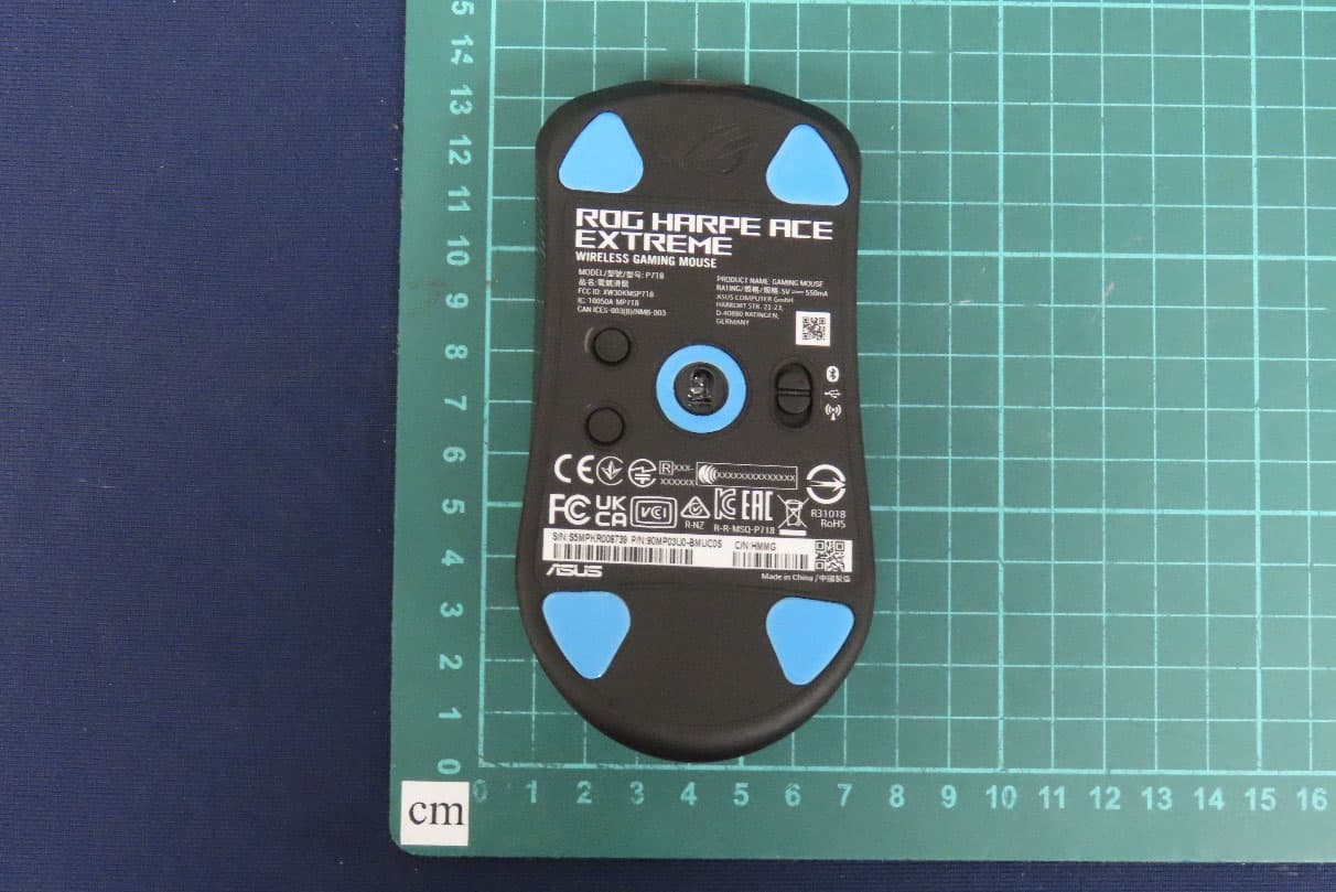
XW3DKMSP718
Jul 02, 2024GAMING MOUSE
Equipment Class
DTS - Digital Transmission System
XW3DKKBX807
Jan 17, 2022WIRELESS GAMING KEYBOARD
Equipment Class
DXX - Part 15 Low Power Communication Device Transmitter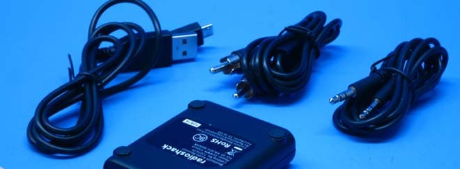
XW3DA-8600BK
Feb 09, 2015Rechargeable Portable Bluetooth Receiver
Equipment Class
DXX - Part 15 Low Power Communication Device Transmitter