Text extracted from the exhibit documents filed with the FCC. Open a document above to read the original.
Echo 2G System User Manual HMS Space Utilization Service HERMAN MILLER INCpage 1 of 9 Echo 2G System User Manual Copyright, 2010, Herman Miller Inc.Revision: 1.1 1. System Overview Echo 2G is a redeployable and scalable multi-tier sensing system that is installed at a customer facility for a period of 3 to 5 weeks to capture space utilization rates. The system employs three technology tiers to capture, aggregate, and transmit workplace utilization data for analysis and trend reporting. Figure 1 Echo 2G System Diagram illustrates the relationship between those tiers. Figure 1 Echo 2G System Diagram HERMAN MILLER INCpage 2 of 9 Echo 2G System User Manual Copyright, 2010, Herman Miller Inc.Revision: 1.1 Furniture Tier This tier determines occupancy by sensing movement of a chair in the customer facility. Motion data is transmitted wirelessly to receivers. Room Tier This tier aggregates motion data from the furniture tier. The data is periodically transmitted to Herman Miller over the Internet via either: 1) the customer LAN or 2) a wireless network comprising a 900 MHz wireless backhaul network, a wireless gateway and a cellular router. Analysis Tier This tier stores all customer data on a secure server at Herman Miller for value-added analysis and reporting. 2. System Deployment and Operation Overview The Echo 2G system is designed to be easily deployed and operated at customer facilities. Receivers are first deployed across the customer study site, and then motes are deployed to predefined spaces in the customer study area. Motes communicate occupancy data to receivers, receivers communicate occupancy data to the Herman Miller DCS over the Internet, and the DCS stores occcupancy data in a database, where it is later used to generate customer reports. The communication protocols between components are illustrated in Figure 2 Data flow diagram with protocols. Figure 2 Data flow diagram with protocols Two types of messages are transmitted from receivers to the DCS (data collection server). First, raw occupancy data is encapsulated in an HTTP or HTTPS POST request, which contains binary data from linked motes. Second, a short heartbeat packet containing operational metrics is transmitted every 10 minutes; this heartbeat packet is used to monitor system status and connectivity. The DCS acknowledges all messages. These acknowledgements may include receiver commands. HERMAN MILLER INCpage 3 of 9 Echo 2G System User Manual Copyright, 2010, Herman Miller Inc.Revision: 1.1 3.1. RF Environment The wireless motes communicate with receivers in the 902-928MHz band, so will not interfere with WiFi, Bluetooth, or Zigbee wireless networks, all of which operate in the 2.4GHz band. 3.2. Power and Data Lines All receivers require power and data connections. They must be placed within wireless range of a subset of motes, where the wireless range between a mote and a receiver is approximately 100 feet indoors. A receiver is capable of linking with over 300 motes, but on average, will link with about 30 motes. To achieve redundant mote coverage, a deployment of 600 motes requires approximately 30 receivers. 3.3. IP Addresses To simplify installation, receivers use dynamic IP addresses. These IP addresses are assigned by the DHCP server on the customer Local Area Network (LAN) along with a subnet mask and default gateway. 3.4. Internet Access Receivers send data via the Internet HTTPS. Heartbeat messages are transmitted every 10 minutes. Occupancy data is transmitted less frequently. If required, receivers may be configured to use a web proxy server. 3.5. Internet Services Receivers use several common Internet services to communicate the space utilization information to the DCS, including DNS to resolve the hostname of the DCS. 3.6. Deployment Laptop A wireless laptop is used to assign individual motes to predefined spaces. A barcode scanner is attached to the USB port of this laptop. This scanner functions as a secondary keyboard. 3. Detailed Process and Deployment Steps Conducting a Space Utilization Study using the Echo 2G system is a four-step process. Step One: Gather Information The customer facility management team provides Herman Miller with information required to conduct the study. This information includes study objectives, location, desired dates, number of motes required, desired reports, a floor plan, and a spreadsheet identifying all workspaces to be monitored during the course of the study. For each of these spaces, the spreadsheet should also contain any optional attributes that may be required to generate desired reports. In this step, Herman Miller obtains the necessary customer IT approvals if the Echo 2G system is to be connected to the customer LAN. Step Two: Setup The required equipment is sent to the customer study site in one or more shipping containers. The key pieces of equipment are the motes and the receivers. HERMAN MILLER INCpage 4 of 9 Echo 2G System User Manual Copyright, 2010, Herman Miller Inc.Revision: 1.1 Important Changes not expressly approved by Herman Miller, Inc. could void the user's authority to operate the equipment. Note: This equipment has been tested and found to comply with the limits for a Class B digital device, pursuant to Part 15 of the FCC Rules. These limits are designed to provide reasonable protection against harmful interference in a residential installation. This equipment generates, uses and can radiate radio frequency energy and, if not installed and used in accordance with the instructions, may cause harmful interference to radio communications. However, there is no guarantee that interference will not occur in a particular installation. If this equipment does cause harmful interference to radio or television reception, which can be determined by turning the equipment off and on, the user is encouraged to try to correct the interference by one or more of the following measures: - Reorient or relocate the receiving antenna. - Increase the separation be…
Text truncated - open the document above for the full version.
Page 1 of 1 RP-6XXXL 12 East Devonwood SOLVING A WAVE OF EMI COMPLIANCE PROBLEMS Romeoville, IL 60446 February 12, 2010 Tel: (815) 293-0772 Page 1 of 1 Fax: (815) 293-0820 Federal Communications Commission Authorization and Evaluation Division 7435 Oakland Mills Rd. Columbia, MD 21046 Industry Canada Certification and Engineering Bureau Ottawa, Ontario K2H 8S2 Canada Reference FCC ID: XWM-HMIMOTE Reference IC ID: 6108A-HMIMOTE Organization: Herman Miller. 2. Long Term Confidentiality Herman Miller requests that the following materials be withheld from public inspection permanently under 47 C.F.R. 0.457 & 0.459: (1) Detailed Circuit Schematics of the EUT (2) Block Diagrams The above materials contain proprietary and confidential information not customarily released to the public. The public disclosure of these materials provides unjustified benefits to its competitors in the market. They are considered confidential trade secrets Authorized Signature Joseph Strzelecki Senior EMC Engineer Radiometrics Midwest Corporation Authorized Agent for Herman Miller.
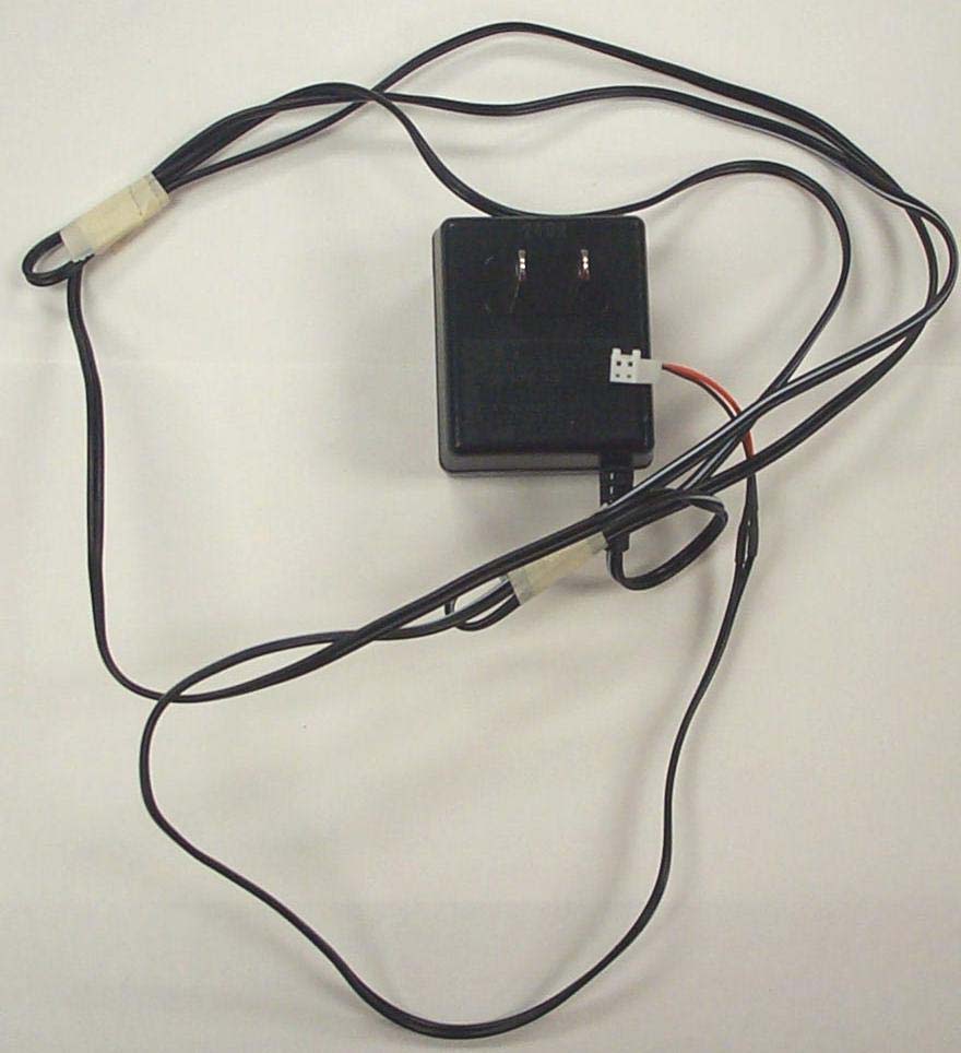
Authorized Agent: Radiometrics Midwest Corporation (815) 293-0772 External EUT Photographs Front of EUT Back of EUT
Authorized Agent: Radiometrics Midwest Corporation (815) 293-0772 ID Label/Location for Mote Mote Label • Text to be printed in light grey ink on black vinyl label • Adhesive is to be permanent acrylic, pressure sensitive Radiometrics Midwest Corporation (815) 293-0772 – [email protected] #6 is the label location
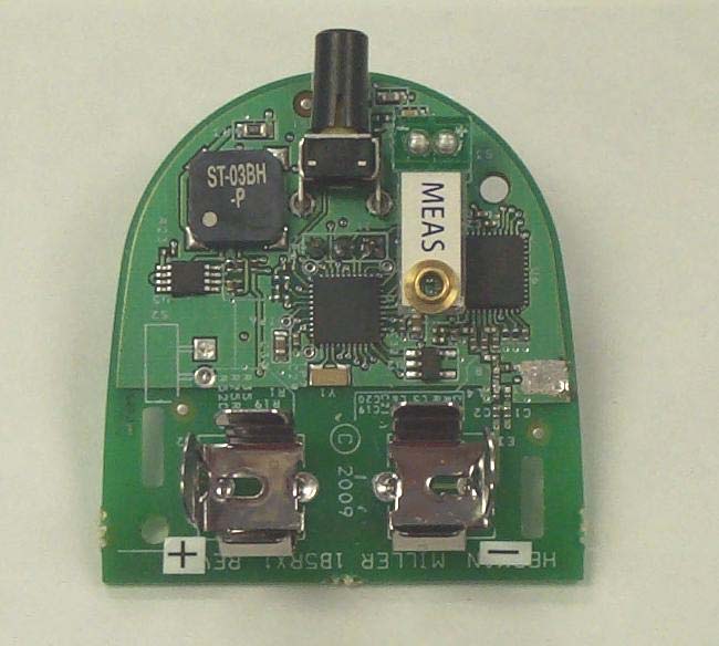
Authorized Agent: Radiometrics Midwest Corporation (815) 293-0772 Internal EUT Photographs Photograph of inside Covers Authorized Agent: Radiometrics Midwest Corporation (815) 293-0772 Photograph of Processor Board-Component Side Authorized Agent: Radiometrics Midwest Corporation (815) 293-0772 Photograph of Processor Board-Foil Side
Radiometrics Midwest Corporation (815) 293-0772 – www.radiomet.com Page 1 of 14 Electromagnetic Compatibility Test Report Tests Performed on a Herman Miller, Incorporated Sensor Transciever, Model 1B5RX2 Radiometrics Document RP-6643A Product Detail: FCC ID: XWM-HMIMOTE IC: 6108A- HMIMOTE Equipment type: 900 MHz Transceiver Test Standards: US CFR Title 47, Chapter I, FCC Part 15 Subpart C FCC Part 15 CFR Title 47: 2008 Industry Canada RSS-210, Issue 7: 2007 as required for Category I Equipment This report concerns: Original Grant for Certification FCC Part 15.249 Tests Performed For: Test Facility: Herman Miller, Incorporated 855 East Main Av., P.O. Box 302 Zeeland, MI 49464-0302 Radiometrics Midwest Corporation 12 East Devonwood Romeoville, IL 60446 Test Date(s): (Month-Day-Year) September 9 thru November 11, 2009 Document RP-6643A Revisions: Rev. Issue Date Affected Pages Revised By 0 February 5, 2010 1 February 11, 2010 1 Joseph Strzelecki RADIOMETRICS MIDWEST CORPORATION - EMC Test Report Testing of the Herman Miller, Incorporated, Model 1B5RX2, Sensor Transceiver RP-6643A Rev. 0 Page 2 of 14 Table of Contents 1 ADMINISTRATIVE DATA.................................................................................................................... 3 2 TEST SUMMARY AND RESULTS......................................................................................................3 2.1 RF Exposure Compliance Requirements ..................................................................................... 3 3 EQUIPMENT UNDER TEST (EUT) DETAILS..................................................................................... 4 3.1 EUT Description............................................................................................................................ 4 3.1.1 FCC Section 15.203 & RSS-GEN Antenna Requirements .................................................... 4 3.2 Related Submittals........................................................................................................................ 4 4 TESTED SYSTEM DETAILS .............................................................................................................. 4 4.1 Tested System Configuration ....................................................................................................... 4 4.2 Special Accessories...................................................................................................................... 4 4.3 Equipment Modifications............................................................................................................... 4 5 TEST SPECIFICATIONS AND RELATED DOCUMENTS .................................................................. 5 6 RADIOMETRICS’ TEST FACILITIES.................................................................................................. 5 7 DEVIATIONS AND EXCLUSIONS FROM THE TEST SPECIFICATIONS ......................................... 6 8 CERTIFICATION ................................................................................................................................. 6 9 TEST EQUIPMENT TABLE ................................................................................................................ 6 10 TEST SECTIONS.............................................................................................................................. 6 10.1 Time of Occupancy (Dwell Time)................................................................................................ 6 10.2 Occupied Bandwidth (20 dB) ...................................................................................................... 7 10.3 Band-edge Compliance of RF Emissions ................................................................................... 9 10.4 Radiated Emissions .................................................................................................................. 10 10.4.1 Radiated Emissions Field Strength Sample Calculation .................................................... 11 10.4.2 Radiated Emissions Test Results ...................................................................................... 12 10.5 Receive Mode Radiated Emissions .......................................................................................... 14 Notice: This report must not be reproduced (except in full) without the written approval of Radiometrics Midwest Corporation. RADIOMETRICS MIDWEST CORPORATION - EMC Test Report Testing of the Herman Miller, Incorporated, Model 1B5RX2, Sensor Transceiver RP-6643A Rev. 0 Page 3 of 14 1 ADMINISTRATIVE DATA Equipment Under Test: A Herman Miller, Incorporated, Sensor Transceiver Model: 1B5RX2 Serial Number: None This will be referred to as the EUT in this Report Date EUT Received at Radiometrics: (Month-Day-Year) Test Date(s): (Month-Day-Year) September 9, 2009 September 9 thru November 11, 2009 Test Report Written By: Test Witnessed By: Joseph Strzelecki Senior EMC Engineer The tests were not witnessed by Herman Miller, Incorporated Radiometrics’ Personnel Responsible for Test: Test Report Approved By Joseph Strzelecki Senior EMC Engineer NARTE EMC-000877-NE Chris W. Carlson Director of Engineering NARTE EMC-000921-NE 2 TEST SUMMARY AND RESULTS The EUT (Equipment Under Test) is a Sensor Transceiver, Model 1B5RX2, manufactured by Herman Miller, Incorporated. The detailed test results are presented in a separate section. The following is a summary of the test results. Emissions Tests Results Environmental Phenomena Frequency Range FCC Section RSS-210 Section Test Result 20 dB Bandwidth Test 902-928 MHz 15.249 A2.9 Pass Radiated Emissions 30 MHz to 25 GHz 15.249 A2.9 Pass AC Conducted Emissions Test 0.15-30 MHz 15.207 RSS-Gen-e 7.2.2 Pass 2.1 RF Exposure Compliance Requirements Since the power output is less than 1 mW, the EUT meets the FCC requirement for RF exposure. Since the EUT is less than 200 mW, it is exempt from RSS-102. There are no power level adjustments an…
Text truncated - open the document above for the full version.
Authorized Agent: Radiometrics Midwest Corporation (815) 293-0772 Test Setup Photographs Photograph of Radiated Emissions Test Setup
| # | Rule Parts | Frequency Range | Power Output |
|---|---|---|---|
| 1 | 15C | 903 MHz - 927 MHz | - |

Base receiver and transmitter for wireless sensor communication
Equipment Class
DXX - Part 15 Low Power Communication Device Transmitter