Text extracted from the exhibit documents filed with the FCC. Open a document above to read the original.
. Nova user guide www.s-w-a-p.co.uk . 1 sWaP Nova user guide www.s-w-a-p.co.uk Contents Welcome to your sWaP ™ Nova 2 Getting started 3 Inserting your SIM card 3 Charging the battery 3 Switching on and off 4 Using the stylus 4 Removing/inserting the memory card 4 Pen Calibration 4 The clock face 4 Menu map 5 Dialling a call 5 Answering a call 5 Voice activation 5 Ending a call 5 Viewing previously dialled calls 5 Using speed dial 5 In-call options 6 Call history 6 Using the wired earphones 6 Your Phone book (Contacts) 7 Adding a new entry 7 Copying entries 7 Finding an entry 7 Other Phone book options 7 Messages 8 SMS messages 8 MMS messages 10 Voice mail server 11 Broadcast message 11 Media 12 Photo album 12 Video player 12 Audio player 13 Sound recorder 14 FM radio 14 WAP 15 Settings 16 Pen Calibration 16 Organizer 16 File manager 18 Stopwatch 18 User Profiles 19 Phone Setup 19 Call Setup 20 Network Setup 20 Security Setup 21 Restore Factory Settings 21 USB link to your computer 22 Important safety information 23 Exposure to radio frequency (RF) signals 23 Operational precautions 23 Medical devices 23 Batteries 24 Vehicles 24 Specific Absorption Rate (SAR) 24 EU directives 25 FCC warning 25 contents . 2 sWaP Nova user guide www.s-w-a-p.co.uk Contents Welcome to your sWaP ™ Nova The most compact multifunction mobile you’ve ever owned. Please also take a moment to read the important safety information located at the rear of this guide. 1.76” high resolution touch screen Speaker Call button End button Power button Microphone Slide out USB port Options port Up/down button Things that you can do: • Insert your SIM card page 3 • Charge the battery page 3 • Switch on page 4 • Dial/answer a call page 5 • Use the earphones page 6 • Use the phone book page 7 • Use messaging page 8 • Use multimedia applications page 12 • Access websites page 15 USB port eject button Stylus SIM card slot Micro SD memory card . 3 sWaP Nova user guide www.s-w-a-p.co.uk Contents 0%100% Getting started Inserting your SIM card Note: Avoid touching the gold contacts of your SIM card. 1 Slide out the stylus from the side of your Nova to reveal the recessed SIM card slot. 2 Slide your SIM card, with its gold contacts upwards and its notched corner towards the Nova, carefully into the slot. 3 Use the end of the stylus to push the SIM card all the way into the slot until it clicks into place. CLICK! Charging the battery You can charge your sWaP Nova using the USB port on your computer and there are two ways to connect it: • Using the slide out USB port, or • Using the supplied USB connection cable. Your sWaP Nova can be switched on or off when it is charging. While charging, the battery indicator on the display will show the progress: USB Charging using the slide out USB port 1 On the underside of your sWaP Nova, slide the USB port button towards the base. The USB connector will be revealed. 2 Carefully insert the USB connector into a vacant socket on your computer. TIP: Keep your finger on the USB port button to prevent the connector from retracting back into sWaP Nova. 3 If your computer is not already switched on, switch it on to start charging your sWaP Nova. Charging using the supplied USB connection cable 1 Carefully insert the small plug of the supplied USB cable into the Options port at the base of your sWaP Nova. Note: Be sure to insert the plug into the correct socket and in the correct orientation. The Options port is the smaller socket, just above the slide USB port. It has rounded corners on its lower side corresponding to similar corners on the plug. 2 The other end of the cable has a standard USB plug which you can attach to your computer. 3 If your computer is not already switched on, switch it on to start charging your sWaP Nova. Options port PC . 4 sWaP Nova user guide www.s-w-a-p.co.uk Contents Switching on and off Press and hold the upper button until the screen responds, then release. Using the stylus The stylus is a slide out pointer with which you can select items more accurately on the touch screen. It is stored in the slot along the right side of your sWaP Nova. Removing/inserting the memory card Your sWaP Nova comes with a 2 GigaByte memory card to store all of your messages, pictures, videos and other information. You do not normally need to remove the memory card, however, there may the occasional need to transfer memory content to, or from, another similarly equipped device. The memory card conforms to the Micro SD standard and is cleverly hidden within the slide out USB port. 1 On the underside of your sWaP Nova, slide the USB port button towards the base. The USB connector will be revealed. 2 Within the underside of the USB connector you will see the end of the concealed memory card. With a finger nail, prise out the memory card from the connector. To reinsert the card, ensure that it is oriented as above and then carefully push it into the slot within the USB connector. The clock face When your sWaP Nova is not engaged in other activities, it will display a clock face (analog or digital): Menu Network saWP Contacts 14 Analog clock face Tap here to access the main menu Tap here to access your Phone book Menu Network Contacts Digital clock face Name of the current network The chosen clock face will overlaid with the current network name plus selectable options (in the two lower corners). The top edge of the clock face will also show one or more of the following status icons: Signal level (0 to 4 bars) Battery charge status ? Missed call SMS message(s) received MMS message(s) received GPRS data connection available Earphones attached Auto keypad lock is off Auto keypad lock is on Bluetooth function enabled Alarm set User profile set to use ring alert only User profile set to use vibrate first and then ring User profile set to use vibrate and ring alerts User profile set to use vibration alert only Stopwatch running Pen Calibration For best results, we recommend that you calibrate the screen of y…
Text truncated - open the document above for the full version.
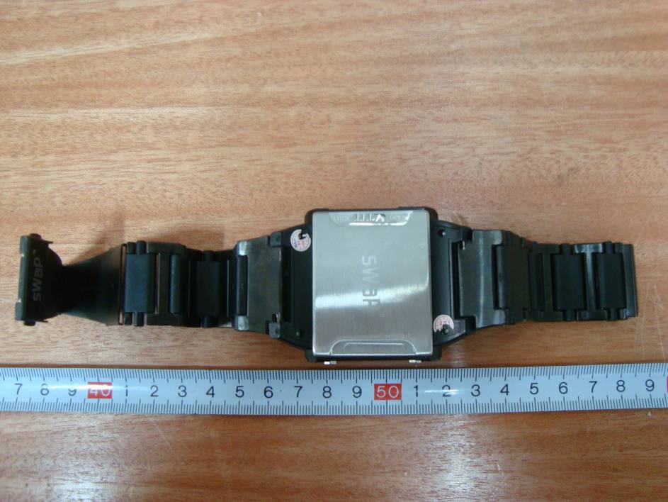
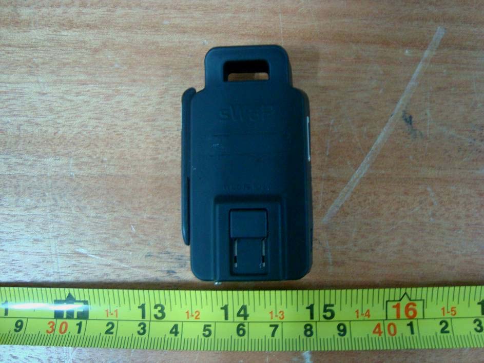
EXHIBIT B - EUT EXTERNAL PHOTOGRAPHS EUT – Front View EUT – Rear View EUT – Left Side View EUT – Right Side View EUT – Bottom View
EXHIBIT A - FCC ID LABELING AND LOCATION FCC ID Label FCC ID Label Location Label here The label shown shall be permanently affixed at a conspicuous location on the device and be readily visible to the user at the time purchase (Labeling requirements per 2.925)
EXHIBIT C - EUT INTERNAL PHOTOGRAPHS EUT – Cover off View EUT – Main Board Top View EUT – Main Board Top Shielding off View EUT – Main Board Bottom View EUT – Main Board Bottom Shielding Off View EUT – LCD Top View EUT – LCD Bottom View EUT – Antenna View-1 EUT – Antenna View-2 EUT – Battery View GSM Antenna Bluetooth Antenna
Note: This test report is prepared for the customer shown above and for the device described herein. It may not be duplicated or used in part without prior written consent from Bay Area Compliance Laboratories Corp. This report must not be used by the customer to claim product certification, approval, or endorsement by NVLAP*, NIST, or any agency of the Federal Government. * This report may contain data that are not covered by the NVLAP accreditation and are marked with an asterisk “*” (Rev.2) FCC PART 15.247 MEASUREMENT AND TEST REPORT For Dyal Trading Limited Solar house, 282 Chase Rd., London, N14 6NZ, UK FCC ID: XWN5017271000040N Report Type: Original Report Product Type: GSM Mobile Phone Test Engineer: Leon Chen Report Number: RSZ10101304-15.247 Report Date: 2010-12-06 Reviewed By: Merry Zhao EMC Engineer Prepared By: Bay Area Compliance Laboratories Corp. (Shenzhen) 6/F, the 3rd Phase of WanLi Industrial Building, ShiHua Road, FuTian Free Trade Zone Shenzhen, Guangdong, China Tel: +86-755-33320018 Fax: +86-755-33320008 Dyal Trading Limited FCC ID: XWN5017271000040N Report No.: RSZ10101304-15.247 Page 2 of 43 FCC Part15.247 Test Report TABLE OF CONTENTS GENERAL INFORMATION.......................................................................................................................................4 PRODUCT DESCRIPTION FOR EQUIPMENT UNDER TEST (EUT) .....................................................................................4 OBJECTIVE...................................................................................................................................................................4 RELATED SUBMITTAL(S)/GRANT(S).............................................................................................................................4 TEST METHODOLOGY..................................................................................................................................................4 TEST FACILITY.............................................................................................................................................................5 SYSTEM TEST CONFIGURATION ..........................................................................................................................6 DESCRIPTION OF TEST CONFIGURATION......................................................................................................................6 EUT EXERCISE SOFTWARE..........................................................................................................................................6 EQUIPMENT MODIFICATIONS.......................................................................................................................................6 LOCAL SUPPORT EQUIPMENT LIST AND DETAILS........................................................................................................6 EXTERNAL I/O CABLE..................................................................................................................................................6 CONFIGURATION OF TEST SETUP.................................................................................................................................6 BLOCK DIAGRAM OF TEST SETUP................................................................................................................................7 SUMMARY OF TEST RESULTS ...............................................................................................................................8 FCC §15.247 (i) & §2.1093 – RF EXPOSURE INFORMATION..................................................................................9 APPLICABLE STANDARD..............................................................................................................................................9 RESULT: .....................................................................................................................................................................10 FCC §15.203 - ANTENNA REQUIREMENT...........................................................................................................11 APPLICABLE STANDARD............................................................................................................................................11 ANTENNA CONNECTOR CONSTRUCTION....................................................................................................................11 FCC §15.207 (a) – AC LINE CONDUCTED EMISSIONS .....................................................................................12 APPLICABLE STANDARD............................................................................................................................................12 MEASUREMENT UNCERTAINTY..................................................................................................................................12 EUT SETUP................................................................................................................................................................12 EMI TEST RECEIVER SETUP.......................................................................................................................................13 TEST EQUIPMENT LIST AND DETAILS.........................................................................................................................13 TEST PROCEDURE......................................................................................................................................................13 TEST RESULTS SUMMARY..........................................................................................................................................13 TEST DATA................................................................................................................................................................13 FCC §15.209, §15.205 & §15.247(d) – RADIATED SPURIOUS EMISSIONS............................…
Text truncated - open the document above for the full version.
EXHIBIT D - TEST SETUP PHOTOGRAPHS AC Line Conducted Emissions - Front View AC Line Conducted Emissions - Side View Below 1 GHz: Spurious Radiated Emissions - Front View Below 1 GHz: Spurious Radiated Emissions - Rear View Above 1 GHz: Spurious Radiated Emissions - Front View Above 1 GHz: Spurious Radiated Emissions - Rear View
| # | Rule Parts | Frequency Range | Power Output |
|---|---|---|---|
| 1 | 15C | 2.40 GHz - 2.48 GHz | 501.00 µW |

Watch Phone
Equipment Class
DSS - Part 15 Spread Spectrum Transmitter