XWR2107Radar (human detection system)
Elta Systems Ltd.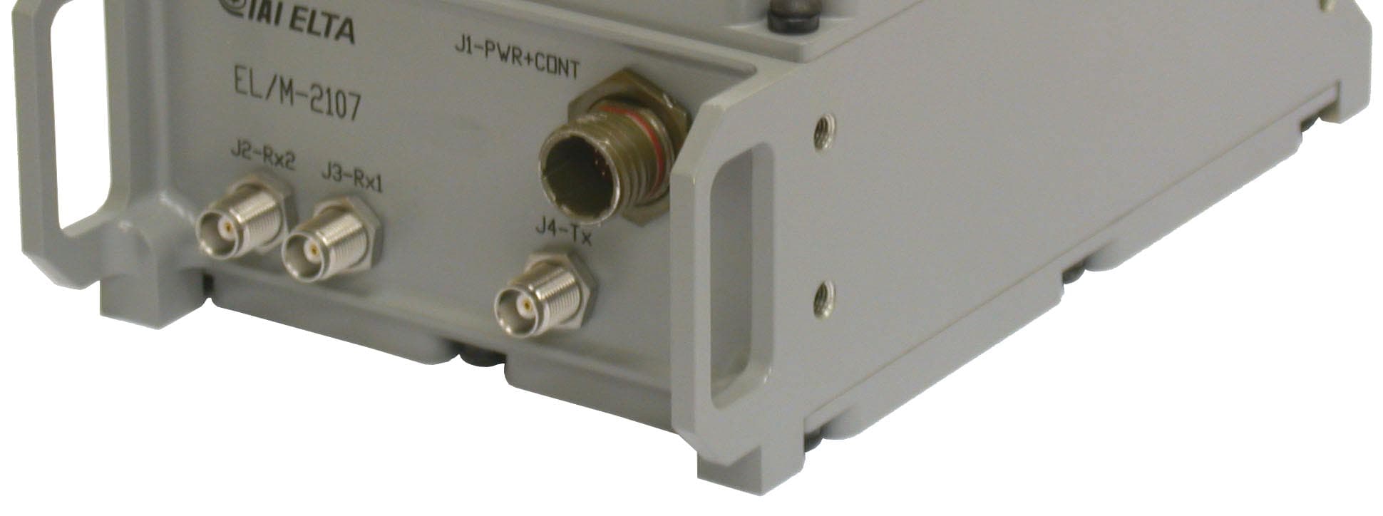
Click to zoom
Application Details
- Equipment Class
- TNB - Licensed Non-Broadcast Station Transmitter
- Date of Grant
- Jan 12, 2010
- Application Purpose
- Original Equipment
- Date of Application
- Jan 10, 2010
- Equipment Note
- Radar (human detection system)
- Frequency Range
- 5394.37500000 - 5406.25000000
- Company
- Elta Systems Ltd.
- Country
- Israel
Documents & Files
Document Text
Text extracted from the exhibit documents filed with the FCC. Open a document above to read the original.
Users Manual
Unclassified HUMAN DETECTION SYSTEM EL/M - 2107 (HDS) USER MANUAL - 2 - This document contains proprietary information of ELTA Systems Ltd. TABLE OF CONTENTS 1. SCOPE .................................................................................................................... 4 1.1. System Goal.........................................................................................................................5 1.2. Applicable Documents ........................................................................................................5 2. SYSTEM OVERVIEW ......................................................................................... 6 3. HDS - DESCRIPTION AND TECHNICAL SPECIFICATIONS ............................................................................................... 7 3.1. Radar Overview ...................................................................................................................7 3.2. HDS Specifications..............................................................................................................9 3.3. Probability of Detection.......................................................................................................9 3.4. Human Detection System - HDS .......................................................................................10 Transceiver 11 3.4.1. Antenna Array ...................................................................................................................12 3.4.2. Connecting Cables .............................................................................................................13 3.4.3. Electro Optical Tracking (optional)...................................................................................16 3.5. System Operation ..............................................................................................................17 3.5.1. Control Buttons .................................................................................................................18 3.5.1. 19 3.6. Environmental Conditions .................................................................................................19 3.7. EL/M-2107 Operation Procedure ......................................................................................20 3.7.1. At start up standby command will send to the Radar ........................................................20 3.7.2. Waiting for legal Ack from the radar, If there isn't Ack or the Ack was illegal then send again the command until three times, if the command was fail then going to recovery procedure.........................................................................20 3.7.3. Waiting for Radar Wakeup command ...............................................................................20 3.7.4. After gets wakeup command, send Operate command, operate command is dividing to three commands: .........................................................................20 3.7.5. In search state if there isn’t plots from the radar, then go to recovery state,...................................................................................................................................20 3.7.6. Every communication fail or radar fail will be written to LOG file with the fail Time.......................................................................................................................20 - 3 - This document contains proprietary information of ELTA Systems Ltd. 4. Installation Instructions for ELM – 2107 system ............................................. 22 4.1. Software installation ..........................................................................................................22 4.2. Hardware installation.........................................................................................................22 5. Notes and warning ............................................................................................... 24 - 4 - This document contains proprietary information of ELTA Systems Ltd. 1. SCOPE This document presents the Human Detection System (HDS) developed and manufactured by ELTA, a subsidiary of Israel Aircraft Industry Ltd. Given are a general radar overview, technical specification and matters related to supply support provisions and quality assurance. The purpose of this document is to assist a potential user in the assessments of the radar proposed, operational constrains, human and technical resources at his disposal etc. Also, it is in both; Manufacturer and potential user best interest, that the latter establish an approach based on the information enclosed and his requirements as regards the prospect of operating the HDS. - 5 - This document contains proprietary information of ELTA Systems Ltd. HDS and IBM PC compatible 1.1. System Goal The HDS goal is to detect and automatically alert entering and outgoing moving persons and vehicles within defined preset boundaries. As it is a very complicated process, customer should have an operational watch-keeping concept, in which the HDS will be one element in the integrated Sensors, Monitors, Command Communication and Control system. 1.2. Applicable Documents The following documents of the issue in effect 1999 form a part of this specification to the extent specified herein. In the event of conflict between the documents referenced herein and the contents of this specification or the detailed design which is an Intellectual Proprietary (IP) of ELTA, the contents of this specification and IP design shall be considered a superseding requirement. a. ISO-9001 b. MIL-HDBK 217F c. MIL-STD-810C d. MIL-STD-1472D e. RS-232 f. RS-422 - 6 - This document contains proprietary information of ELTA Systems Ltd. 2. SYSTEM OVERVIEW The system is based on ELTA’s vast experience in high-resolution technology and innovative radars. The system automatically detects moving objects and persons within the covered area. It allows segregation of persons …
Text truncated - open the document above for the full version.
External Photos
Elta Systems Ltd. FCC ID:XWR2107 Page 1 of 4 EXTERNAL PHOTOGRAPHS This document contains 3 photographs Elta Systems Ltd. FCC ID:XWR2107 Page 2 of 4 Photograph No.1 ELM 2107 radar general view Antenna Main body Elta Systems Ltd. FCC ID:XWR2107 Page 3 of 4 Photograph No.2 ELM 2107 radar, main body front view Elta Systems Ltd. FCC ID:XWR2107 Page 4 of 4 Photograph No.3 ELM 2107 radar, main body rear side view
ID Label/Location Info
Elta Systems Ltd. FCC ID:XWR2107 Page 1 of 2 Label The label shown below will be affixed on the side panel of the ELM2107 radar. Label location Label with FCC ID:XWR2107 will be placed here DC BA 4321 DC BA 4321 I NFORMATION CONTAINED HEREIN IS PROPRIETARY AND MAY NOT BE REPRODUCED WITHOUT WRITTEN CONSENT ZONE REV DESCRIPTION DATE APPROVED NAME PLATE SIZE CAGE CODE PART No. (DWG. No.) REV. A3 1021E502-001 - SCALE : SHEET 1 OF 1 SECURITY UNCLASSIFIED USED ON S.C DESIGN DRAWN CHECK APVD S.C D.R 29/11/0929/11/0929/11/09 NAME DATE D.R 29/11/09 UNLESS OTHERWISE SPECIFIED VIEW PROJECTIONS: DIMENSIONS: mmGENIRAL TOLERANCES: X ± XX ± XXX ± XXXX ± ANGLES ± SURFACE ROUGHNESS SEE SEPARATE PARTS LIST TITLE RELEASED 29/11/09 D.R. -
Parts List/Tune Up Info
PART / DOC. NO. 1021E406-001 REV.- PAGE 1 OF 6 PAGES DESIGN & MFG. OF ELECTRONIC EQUIPMENT P.O.B. 330 ASHDOD 77102 ISRAEL TEL 972-8-8572333 FAX: 972-8-8563930 TELEGER: ELTASHDOD UNCLASSIFIED FUNCTIONAL ATR for EL/M-2107 P / N 1021E500-001 RESTRICTION ON USE, DUPLICATION, OR DISCLOSURE OF PROPRIETARY INFORMATION This document contains proprietary information which is the sole property of Elta Systems Ltd. The document is submitted to the recipient for his use only. By receiving this document the recipient undertakes not to duplicate the document or to disclose in part of, or the whole of, any o f the information contained herein to any third party without receiving before hand, written permission from the submittin g company. UNCLASSIFIED PART / DOC. NO. 1021E406-001 REV.- PAGE 2 OF 6 PAGES This document contains proprietary information of ELTA Systems Ltd. REVISIONS REV. DESCRIPTION DATE APPR. - RELEASED 24.06.07 Y. A. UNLESS OTHERWISE NOTED ALL PAGES ARE OF ORIGINAL ISSUE REV. - - - - - - PAGE 1 2 3 4 5 6 REV. PAGE REV. PAGE REV. DRAFTSMAN: DESIGNER: Y. A. CHECKER: D. R. PROJECT ENG. : Y. A. MECH. ENG. : D. R. PRODUCT ASSURANCE: A. J. APPROVAL: A.D. T I T L E: FUNCTIONAL ATR for EL/M-2107 Unclassified PART / DOC. NO. 1021E406-001 REV.- PAGE 3 OF 6 PAGES This document contains proprietary information of ELTA Systems Ltd. TABLE OF CONTENTS PARA. TITLE PAGE 1. INTRODUCTION............................................................................................................ 4 1.1 APPLICABLE DOCUMENTS........................................................................................................... 4 2. VISUAL TEST.................................................................................................................... 4 2.1 VISUAL IDENTIFICATION............................................................................................................. 4 2.2 VISUAL INSPECTION.................................................................................................................... 5 3. LIST OF REQUIRED TEST EQUIPMENT................................................ 5 4. Electrical test Current test 4.1.4 TRANSMISSION TEST.............................................................6 4.1.5 Power signal...........................................................................6 4.2.4 Average noise signal level..........................................................6 4.2.6 Signal Injection.......................................................................6 4.2.9 Sensitivity test........................................................................6 4.3 Testing el/m-2107.....................................................................6 5. APPROVAL .................................................................................................................................. 6 Unclassified PART / DOC. NO. 1021E406-001 REV.- PAGE 4 OF 6 PAGES This document contains proprietary information of ELTA Systems Ltd. 1. Introduction a. This manual provides the Acceptance Test Results (ATR) EL/M-2107 P/N 1020E500-001. The ATR manual includes visual, mechanical and electrical results according the ATP logbook P/N 1021E406-001. b. For results not meeting the required specification, the appropriate place in the ATR should be marked and a failure report shall be filled. c. The test procedure is only completed if all test results and / or pages of the ATR are signed where required. d. Verify that the ATP and the ATR in your possession are the latest revisions. 1.1 Applicable Documents a. b. 5905B884-001 – EL/M-2107 ESS. 1021E405-001 – FUNCTIONAL ATP for EL/M-2107. 2. Visual test 2.1 Visual identification No'. LRU P/N REV. SERIAL NO. 1. EL/M-2107 1021E500-001 Table 2.1: Visual identification of the LRU’s Unclassified PART / DOC. NO. 1021E406-001 REV.- PAGE 5 OF 6 PAGES This document contains proprietary information of ELTA Systems Ltd. 2.2 Visual Inspection Verify that each of the following LRU’s has passed its ATP and verify the availability of the LRU’s service tag or C.O.C. Inspect each of the following LRU’s and verify: No. DESCRIPTION REQUIREMENTS RESULTS 1. Identification plate See ATP 2. Workmanship See ATP 3. Securing of connectors See ATP 4. Securing of hardware See ATP Table 2.2 Visual inspections 3. List Of Required Test Equipment Verify that all test equipment serviceable tags are updated. Unclassified PART / DOC. NO. 1021E406-001 REV.- PAGE 6 OF 6 PAGES This document contains proprietary information of ELTA Systems Ltd. 4. Electrical test 4.1.2 Current test 4.1.4 TRANSMISSION TEST Pass/fail Band [MHz] Upper frq. [MHz] Lower freq.[MHz] Required Measured Required Measured Required Measured 60 ± 5 5520 Max 5330 Min 4.1.5 POWER SIGNAL Pass/fail Power Trans [dBm] Measured Min Required +18 4.2.4 AVERAGE NOISE SIGNAL LEVEL Pass/fail Max Required Noise level CH 2 [dBm] Noise level CH 1 [dBm] -97 4.2.6. SIGNAL INJECTION Pass/fail Min Required [dBm] Ch1 Measured [dBm] Ch 2 Measured [dBm] -40 4.2.9 SENSITIVITY TEST EL/M-2107 sensitivity Pass/fail Measured [dBm] ATT. [db] Max Required [dbm] 110- 4.3 TESTING EL/M-2107 Pass/fail Detection angel (80º) Detecting & tracking False alarms 5 APROVAL Name Signature Date Manufacturer Q.A Customer Supply Voltage Current (Amp.) Measured Required 0.7 ± 0.15 Amp
RF Exposure Info
Elta Systems Ltd. FCC ID:XWR2107 RF Exposure Evaluation according to FCC 47 CFR part 1 §1.1307 The transceiver is classified as fixed. The calculation was done for minimum safety distance. Limit for power density for general population/uncontrolled exposure is 1 mW/cm 2 (for 1500 –100,000 MHz frequency range). The power density P (mW/cm 2 ) = P T / 4π ππ π r 2 P T is the transmitted power, which is equal to the peak transmitter output power plus maximum antenna gain. The maximum equivalent isotropically radiated power EIRP is P T = 20.1 dBm + 13 dBi = 33.1 dBm = 2042 mW, where 20.1 dBm is the EUT maximum output power; 13 dBi –antenna gain. The minimum safe distance “r”, where RF exposure does not exceed FCC permissible limit, is r = sqrt { P T / (Px4π)} = sqrt {2042/12.56} ≈13 cm. General public will not be exposed to dangerous RF level.
Test Report
Hermon Laboratories Ltd. Harakevet Industrial Zone, Binyamina 30500, Israel Tel. +972-4-6288001 Fax. +972-4-6288277 E-mail: [email protected] Page 1 of 54 Report ID: ELTRAD_FCC.20144.doc Date of Issue: 11/15/2009 Electrical 839.01 TEST REPORT ACCORDING TO: FCC CFR 47 Part 90 FOR: Elta Systems Ltd. Radar Model:ELM-2107 This report is in conformity with ISO/ IEC 17025. The "A2LA Accredited" symbol endorsement applies only to the tests and calibrations that are listed in the scope of Hermon Laboratories accreditation. The test results relate only to the items tested. This test report shall not be reproduced in any form except in full with the written approval of Hermon Laboratories Ltd. Report ID: ELTRAD_FCC.20144.doc Date of Issue: 11/15/2009 Page 2 of 54 Table of contents 1 Applicant information..................................................................................................................................................... 3 2 Equipment under test attributes .................................................................................................................................... 3 3 Manufacturer information .............................................................................................................................................. 3 4 Test details.................................................................................................................................................................... 3 5 Tests summary.............................................................................................................................................................. 4 6 EUT description............................................................................................................................................................. 5 6.1 General information....................................................................................................................................................... 5 6.2 Ports and lines .............................................................................................................................................................. 5 6.3 Support and test equipment .......................................................................................................................................... 5 6.4 Changes made in the EUT ............................................................................................................................................ 5 6.5 Test configuration.......................................................................................................................................................... 6 6.6 Transmitter characteristics ............................................................................................................................................ 7 7 Transmitter tests according to 47CFR part 90 requirements......................................................................................... 8 7.1 Peak output power test.................................................................................................................................................. 8 7.2 Occupied bandwidth test ............................................................................................................................................. 10 7.3 Emission mask test ..................................................................................................................................................... 14 7.4 Radiated spurious emission measurements................................................................................................................ 17 7.5 Spurious emissions at RF antenna connector test ...................................................................................................... 27 7.6 Frequency stability test................................................................................................................................................ 37 7.7 RF exposure................................................................................................................................................................ 39 8 APPENDIX A Test equipment and ancillaries used for tests....................................................................................... 40 9 APPENDIX B Measurement uncertainties................................................................................................................... 42 10 APPENDIX C Test laboratory description ................................................................................................................... 43 11 APPENDIX D Specification references ....................................................................................................................... 43 12 APPENDIX E Test equipment correction factors......................................................................................................... 44 13 APPENDIX F Abbreviations and acronyms................................................................................................................. 54 Report ID: ELTRAD_FCC.20144.doc Date of Issue: 11/15/2009 Page 3 of 54 1 Applicant information Client name: Elta Systems Ltd. Address: 100 Yitzhack Hanassi Blvd., P.O.B. 330, Ashdod, 77102, Israel Telephone: +972 8857 2891 Fax: +972 8857 2798 E-mail: [email protected] Contact name: Mr. Moti Faivelovitz 2 Equipment under test attributes Product name: Radar Model(s): ELM-2107 Serial number: 236 Hardware version: PN 1021E500-001 Software release: 3_0_541 Receipt date 10/22/2009 3 Manufacturer information Manufacturer name: Elta Systems Ltd. Address: 100 Yitzhack Hanassi Blvd., P.O.B. 330, Ashdod, 77102, Israel Telephone: +972 8857 2891 Fax: +972 8857 2798 E-Mail: [email protected] Contact name: Mr. Moti Faivelovitz 4 Test details Project ID: 20144 Location: Hermon Laboratories Ltd. Harakevet Industrial Zone, Binyami…
Text truncated - open the document above for the full version.
Test Setup Photos
Elta Systems Ltd. FCC ID:XWR2107 Page 1 of 8 SETUP PHOTOGRAPHS This document contains 7 photographs Elta Systems Ltd. FCC ID:XWR2107 Page 2 of 8 Photograph No.1 Peak output power measurement setup Elta Systems Ltd. FCC ID:XWR2107 Page 3 of 8 Photograph No.2 Occupied bandwidth, emission mask, conducted spurious emissions measurement setup Elta Systems Ltd. FCC ID:XWR2107 Page 4 of 8 Photograph No.3 Spurious emissions measurement setup in the anechoic chamber below 30 MHz Elta Systems Ltd. FCC ID:XWR2107 Page 5 of 8 Photograph No.4 Spurious emissions measurement setup in the anechoic chamber in 30 -1000 MHz Elta Systems Ltd. FCC ID:XWR2107 Page 6 of 8 Photograph No.5 Spurious emissions measurement setup in the anechoic chamber above 1000 MHz Elta Systems Ltd. FCC ID:XWR2107 Page 7 of 8 Photograph No.6 Radiated emissions measurement setup at the OATS above 1000 MHz Elta Systems Ltd. FCC ID:XWR2107 Page 8 of 8 Photograph No.7 Frequency stability measurement setup
Contact Information
Applicant
ISAHAR GABAY(EMC GROUP LEADER)
Technical Contact
Hermon Laboratories Ltd.Michael Nikishin
[email protected]+972 4626 8440
Harakevet Industrial zone, P.O.Box 23 · Binyamina · Israel
Non-Technical Contact
Elta Systems Ltd.Yehuda Grin
[email protected]+972 8857 2891
Test Firm
Hermon Laboratories Ltd.Alexander Usoskin
Technical Specifications
| # | Rule Parts | Frequency Range | Power Output | Emission | Tolerance |
|---|---|---|---|---|---|
| 1 | 90 | 5.39 GHz - 5.41 GHz | 102.00 mW | 209MF0N | 44186.0000000000 Hz |