XX6-STP8280TETRA Portable Terminal
Sepura Limited
Click to zoom
Application Details
- Equipment Class
- TNE - Licensed Non-Broadcast Transmitter Held to Ear
- Date of Grant
- Aug 08, 2012
- Application Purpose
- Original Equipment
- Date of Application
- Aug 08, 2012
- Equipment Note
- TETRA Portable Terminal
- Frequency Range
- 862.00000000 - 869.00000000
- Company
- Sepura Limited
- Country
- United Kingdom
Documents & Files
Document Text
Text extracted from the exhibit documents filed with the FCC. Open a document above to read the original.
Users Manual
sepura TETRA Terminals Product Guide MOD-10-1164 Issue 9 © SEPURA PLC 2012 MOD-10-1164 sepura TETRA Terminals Product Guide 06-06-12 Page 2 of 45 Issue 9 © Sepura plc 2012 Contents CONVENTIONS _______________________________________________ 3 REGULATORY STATEMENTS ___________________________________ 4 Compliance with Standards _________________________________________________ 4 North American and Canadian markets ________________________________________ 5 Marchés nord-américain et canadien __________________________________________ 7 OPERATIONAL REQUIREMENTS ________________________________ 9 Operating Conditions _______________________________________________________ 9 IP, IEC and ATEX Ratings ___________________________________________________ 9 HANDHELD RADIO RANGE ____________________________________ 10 STP Series Radios ________________________________________________________ 11 SRH3500, SRH3800, SRH3900 _______________________________________________ 27 MOBILE / GATEWAY RADIO RANGE ____________________________ 32 SRG3000 Mobile / Gateway Transceiver ______________________________________ 33 Standard Console _________________________________________________________ 34 Colour Console ___________________________________________________________ 34 Handset Based Console ___________________________________________________ 35 Applications Interface Unit _________________________________________________ 36 Mobile / Gateway Radio Accessories _________________________________________ 36 Mobile / Gateway Radio Audio Control _______________________________________ 37 RADIO OPERATION __________________________________________ 38 HEALTH AND SAFETY ________________________________________ 39 User Information __________________________________________________________ 39 Compliance with Standards ________________________________________________ 42 GLOSSARY _________________________________________________ 43 ACKNOWLEDGEMENTS ______________________________________ 44 NOTICE ____________________________________________________ 45 Contact Details ___________________________________________________________ 45 MOD-10-1164 sepura TETRA Terminals Product Guide 06-06-12 Page 3 of 45 Issue 9 © Sepura plc 2012 CONVENTIONS This guide uses the following formatting and graphical conventions. Convention Description Note icon. Emphasises related, reinforcing, or important information. Tip icon. Suggests alternative methods for accomplishing tasks or procedures. Caution icon. Indicates actions or processes that require caution from the user. MOD-10-1164 sepura TETRA Terminals Product Guide 06-06-12 Page 4 of 45 Issue 9 © Sepura plc 2012 REGULATORY STATEMENTS COMPLIANCE WITH STANDARDS RADIATION PROTECTION The radios fully comply with the NRPB specification EN50360 (EN50361) and the ICNIRP guidelines for exposure to electromagnetic fields mandated for mobile phones (2W per kg over a 10g sample). ELECTRO MAGNETIC COMPATIBILITY The radios meet the EMC requirements specified by the ETSI specifications: ETSI EN 301 489-1, ETSI EN 301 489-18 TYPE APPROVAL The radios have been self-certified against the R&TTE Directive EN 303 035-1 and are CE marked accordingly. ENVIRONMENTAL The radios fully comply with the following environmental regulatory requirements: The MIL STD 810E standard for Salt Fog: The MIL STD 810E standard for Driving Sand (SRH3000 radios only) The radios have been self-certified to fully comply with all environmental aspects detailed by ETSI EN 300 019. These include mechanical and climatic tests covering such things as drop, vibration, bump and shock as well as temperature and humidity. STP8X SPECIFIC ENVIRONMENTS The STP8X radio is designed to work in the following hazardous environments... GAS ENVIRONMENT The STP8X radio complies with the following specifications for operation in a gas environment International IECEx Specifications: Ex ib IIC T4 Gb (-20°C <= Ta <= +55°C) European ATEX Specification II 2G Ex ib IIC T4 Gb (-20°C<=Ta<=+55°C) DUST ENVIRONMENT The STP8X radio complies with the following specifications for operation in a dust environment: International IECEx Specifications: Ex ib IIIC T90°C Db (-20°C<=Ta <= +55°C) European ATEX Specification II 2D Ex ib IIIC T90°C (-20°C<=Ta<=+55°C) Db IP6x MOD-10-1164 sepura TETRA Terminals Product Guide 06-06-12 Page 5 of 45 Issue 9 © Sepura plc 2012 STP8X CONDITIONS FOR SAFE USE The equipment has been impact tested according to the low risk of mechanical danger. Care should be taken to avoid mechanical impact. Use only Sepura approved batteries, antennas and accessories. The battery pack must not be removed or replaced in the hazardous area. The antenna must not be removed / replaced in the hazardous area. The RuSC cover or RuSC connector must not be removed or replaced in the hazardous area. RADIO OPERATION The radios meet the requirements specified by the ETSI specification EN 300 394-1. SAFETY AND VEHICLE CERTIFICATION AGENCY (VCA) The radios fully comply with the User Safety specification EN60950, and the Automotive Directive detailed in 2006/28/EC. NORTH AMERICAN AND CANADIAN MARKETS The following regulatory statements apply to users in the North American and/or Canadian markets. SRG3900 RADIOS Changes or modifications not expressly approved by the party responsible for compliance could void the user‟s authority to operate the equipment (FCC rule part 15.21). This device complies with part 15 of the FCC Rules. Operation is subject to the following two conditions: (1) This device may not cause harmful interference, and (2) this device must accept any interference received, including interference that may cause undesired operation. (FCC Rule Part 15.19(a)(3)). NOTE: This equipment has been tested and found to comply with the limits for a Class A digital device, pursuant to part 15 of the FCC Rules. These limits are designed to provide reasonable protection against harmful interference when the equipment is operated in a commercial environment. T…
Text truncated - open the document above for the full version.
Users Manual
STP8000 Series CAR KIT INSTALLATION & USER GUIDE 1 sepura INTRODUCTION The STP8000 car kit provides secure retention of the radio within a cradle. The car kit features battery charging, external antenna connection, external PTT keypad, hands-free operation with the external microphone and loudspeaker. A standard RS232 data port and USB is provided for data transfer applications. Connections are provided for optional accessories. Cable colour Electrical parameters Fuse RED Vehicle +ve (12v MAX) 4 Amp BLACK Vehicle –ve (vehicle chassis) n/a PINK Open drain Output, max current 0.5A Protected by a re-settable fuse provided inside car kit YELLOW Open drain Output, max current 0.5A Protected by a re-settable fuse provided inside car kit BLUE Input Signal Level 12VDC (200 uA max) 1 Amp sepura or MICSMICALARMPTT REMOTE PTT CRADLE Front INTERFACE UNIT (user interface) USBDATA (RS232)SXC HANDSET/FIST MIC Loudspeaker Output 50Ω Rear INTERFACE UNIT (vehicle harness) Antenna Connections for accessories STP8000 Series CAR KIT INSTALLATION & USER GUIDE 2 sepura Information The STP8000 car kit is designed for 12 V negative earth systems. In vehicles with a 24 V supply, an approved converter must be used, NOT a 12 V tap on the battery. The equipment is to be installed in accordance with the requirements of local radio communications authorities and/or Health and Safety regulations. 12 V supply leads, antenna cables and speaker wiring is to be routed as far away as possible from gas or fuel lines. This reduces the risk to safety in the event of a leak. The car kit should be positioned so that it does not obstruct, or become at risk of damage from, any occupant or carried items. All cabling should be hidden and not left loose. Radio Software For correct operation of the STP8000 with the car kit, the STP8000 must have radio software of v9.0 greater. INSTALLATION This installation guide provides basic installation information and is not intended to be definitive, as different types of vehicles will require different ways installation arrangements. The installer must ensure that fixing screws of an appropri- ate length are used (some installations may require different screws). The information given here is general and for guid- ance only. The installation must comply with in-country CODE OF PRACTICE for the installation of mobile radio and related ancillary equipment in land based vehicles — e.g. FCS1362 (formally MPT1362)see http:// www.fcs.org.uk. WARNING 1 Disconnect the vehicle’s battery before commencing installation (be aware of effect on public broadcast radio security code, alarm systems and some engine man- agement systems). 2 Do not smoke, or use naked flames, when working near the vehicle’s fuel system. 3 Ensure that fuel lines, hydraulic lines and existing cables are not damaged during installation. 4 Ensure that the installation does not impede the normal operation of the vehicle, including the operation of any safety device, e.g., airbags and seatbelt tensioners. 5 Speed control, fuel injection, anti-lock braking, naviga- tion, air bag and other electronic systems are relatively immune to RF interference. However, if difficulty is experienced, or faulty operation suspected, consult the vehicle’s dealer. 6 This equipment is suitable for 12 V negative earth vehi- cles only. Use on other supply systems will result in damage to the equipment. 7 No part of the equipment should be mounted such that injury to the occupants is likely during an accident. 8 Prolonged operation of the radio in the car kit with the vehicle engine switched off, could drain the vehicle’s battery. 9 Prolonged operation at high volume levels may cause the interface unit to become hot. Cradle The cradle should be attached to the vehicle’s interior in a convenient position using the mounting brackets. The location of the cradle should allow the user unrestricted access to the radio’s controls. The radio’s display should be visible to the user but not distracting when driving. The cradle should not prevent the user from controlling or operating the vehicle. Interface Unit Attach the interface unit to the vehicle’s interior, using, if appropriate, the four 25mm self-tapping screws provided. The interface unit should be mounted on a firm surface in- side the passenger compartment, within reach of all cabling. The data socket should be easily accessible. Connect the lead from the cradle to the socket labelled “RADIO”. Con- nect the vehicle harness to the socket labelled “AUTO”. Note: Do not install the interface unit in engine compartment. Cables & Connectors Ensure the cables due not rub against sharp edges and are not subjected to undue stress. Power Connection (thick red and black wires) • The positive power line must include a fuse as close as possible to the power source. The negative power line must be connected close to the battery-to-vehicle-body connexion (not directly to the battery) and must not include a fuse. • It is recommended that the power cable runs are kept as short as possible. • The blue wire provides an ignition sensing input. If ignition switching is required, trim the wire to length so that it can be wired, via a fuse, to the ignition switch, using the splicing connector provided. Otherwise this wire must be connected, via a fuse, to the permanent positive supply. A fuse must always be fitted close to where the wire is connected. Fuse Ratings Positive supply 4 A Ignition sense 1 A The ring terminated wires are for direct connection to the vehicle battery (do not connect at this stage); supply should not be taken from any other point. Feed the bullet terminated free ends through the bulkhead, using a grommet to protect the wires. Locate the free ends under the dashboard and connect to the main wiring har- ness supplied with the car kit. Connect the ring terminals to the vehicle battery when the rest of the installation (see fol- lowing sections) is complete and satisfactory. Remote Microphone The remote microp…
Text truncated - open the document above for the full version.
Users Manual
STP8000 Series CAR KIT INSTALLATION & USER GUIDE 1 sepura INTRODUCTION The STP8000 car kit provides secure retention of the radio within a cradle. The car kit features battery charging, external antenna connection, external PTT keypad, hands-free operation with the external microphone and loudspeaker. A standard RS232 data port and USB is provided for data transfer applications. Connections are provided for optional accessories. Cable colour Electrical parameters Fuse RED Vehicle +ve (12v MAX) 4 Amp BLACK Vehicle –ve (vehicle chassis) n/a PINK Open drain Output, max current 0.5A Protected by a re-settable fuse provided inside car kit YELLOW Open drain Output, max current 0.5A Protected by a re-settable fuse provided inside car kit BLUE Input Signal Level 12VDC (200 uA max) 1 Amp sepura or MICSMICALARMPTT REMOTE PTT CRADLE Front INTERFACE UNIT (user interface) USBDATA (RS232)SXC HANDSET/FIST MIC Loudspeaker Output 50Ω Rear INTERFACE UNIT (vehicle harness) Antenna Connections for accessories STP8000 Series CAR KIT INSTALLATION & USER GUIDE 2 sepura Information The STP8000 car kit is designed for 12 V negative earth systems. In vehicles with a 24 V supply, an approved converter must be used, NOT a 12 V tap on the battery. The equipment is to be installed in accordance with the requirements of local radio communications authorities and/or Health and Safety regulations. 12 V supply leads, antenna cables and speaker wiring is to be routed as far away as possible from gas or fuel lines. This reduces the risk to safety in the event of a leak. The car kit should be positioned so that it does not obstruct, or become at risk of damage from, any occupant or carried items. All cabling should be hidden and not left loose. Radio Software For correct operation of the STP8000 with the car kit, the STP8000 must have radio software of v9.0 greater. INSTALLATION This installation guide provides basic installation information and is not intended to be definitive, as different types of vehicles will require different ways installation arrangements. The installer must ensure that fixing screws of an appropri- ate length are used (some installations may require different screws). The information given here is general and for guid- ance only. The installation must comply with in-country CODE OF PRACTICE for the installation of mobile radio and related ancillary equipment in land based vehicles — e.g. FCS1362 (formally MPT1362)see http:// www.fcs.org.uk. WARNING 1 Disconnect the vehicle’s battery before commencing installation (be aware of effect on public broadcast radio security code, alarm systems and some engine man- agement systems). 2 Do not smoke, or use naked flames, when working near the vehicle’s fuel system. 3 Ensure that fuel lines, hydraulic lines and existing cables are not damaged during installation. 4 Ensure that the installation does not impede the normal operation of the vehicle, including the operation of any safety device, e.g., airbags and seatbelt tensioners. 5 Speed control, fuel injection, anti-lock braking, naviga- tion, air bag and other electronic systems are relatively immune to RF interference. However, if difficulty is experienced, or faulty operation suspected, consult the vehicle’s dealer. 6 This equipment is suitable for 12 V negative earth vehi- cles only. Use on other supply systems will result in damage to the equipment. 7 No part of the equipment should be mounted such that injury to the occupants is likely during an accident. 8 Prolonged operation of the radio in the car kit with the vehicle engine switched off, could drain the vehicle’s battery. 9 Prolonged operation at high volume levels may cause the interface unit to become hot. Cradle The cradle should be attached to the vehicle’s interior in a convenient position using the mounting brackets. The location of the cradle should allow the user unrestricted access to the radio’s controls. The radio’s display should be visible to the user but not distracting when driving. The cradle should not prevent the user from controlling or operating the vehicle. Interface Unit Attach the interface unit to the vehicle’s interior, using, if appropriate, the four 25mm self-tapping screws provided. The interface unit should be mounted on a firm surface in- side the passenger compartment, within reach of all cabling. The data socket should be easily accessible. Connect the lead from the cradle to the socket labelled ―RADIO‖. Con- nect the vehicle harness to the socket labelled ―AUTO‖. Note: Do not install the interface unit in engine compartment. Cables & Connectors Ensure the cables due not rub against sharp edges and are not subjected to undue stress. Power Connection (thick red and black wires) The positive power line must include a fuse as close as possible to the power source. The negative power line must be connected close to the battery-to-vehicle-body connexion (not directly to the battery) and must not include a fuse. It is recommended that the power cable runs are kept as short as possible. The blue wire provides an ignition sensing input. If ignition switching is required, trim the wire to length so that it can be wired, via a fuse, to the ignition switch, using the splicing connector provided. Otherwise this wire must be connected, via a fuse, to the permanent positive supply. A fuse must always be fitted close to where the wire is connected. Fuse Ratings Positive supply 4 A Ignition sense 1 A The ring terminated wires are for direct connection to the vehicle battery (do not connect at this stage); supply should not be taken from any other point. Feed the bullet terminated free ends through the bulkhead, using a grommet to protect the wires. Locate the free ends under the dashboard and connect to the main wiring har- ness supplied with the car kit. Connect the ring terminals to the vehicle battery when the rest of the installation (see fol- lowing sections) is complete and satisfactory. Remote Microphone The remote microp…
Text truncated - open the document above for the full version.
Users Manual
SPR-DOC-003060 Vehicle Antenna Installation Guide sepura Sepura plc, Radio House. SPR-DOC-03060 St Andrews Road, Cambridge CB4 1GR Issue 1 www.sepura.com INTRODUCTION When installing any TETRA antenna to a vehicle, it is the responsibility of the installer to ensure that the location of the antenna is considered not only for best RF performance but more importantly in order to minimize the potential for RF exposure to third parties. To minimise the potential risk of RF exposure to third parties, antennas should ideally be fitted to locations on the vehicle that ensures that the distance between the radiating antenna and third parties is at least 20cm or if greater the minimum safe distance required to meet the General Exposure limit for that antenna fitted. If this General Exposure distance cannot be met then the radiating antenna must be placed in a location that ensures the Occupation limit cannot exceeded. A list of minimum distances for Sepura supplied TETRA antennas are shown in table 1 below. The outline drawing below shows one example of how third parties may come into proximity of the installed antenna. Should it not be possible to maintain the minimum safe distance between third parties and the radiating antenna, then action must be taken by the installer to reduce the potential for exposure at the specified minimum distance such that the General Exposure limits are not exceeded. TABLE 1 Application/Power Sepura Part No Antenna type Antenna Gain Frequency Range Minimum Safe Distance General Occupational STP Car kit 32.5dBm 9525 800 41080 5/8 wave, M8 mount 7dBi 450- 470MHz 25cm 20cm STP Car kit 32.5dBm 300-00390 Co-linear whip, M8 mount 5dBi 817- 869MHz 20cm 20cm STP Car kit 32.5dBm 9525 800 41021 Co-linear whip, M8 mount 5dBi 817- 869MHz 20cm 20cm SRG/40dBm 9525 800 41079 ¼ wave, M8 mount 2dBi 450- 470MHz 32cm 20cm SRG/40dBm 9525 800 41080 5/8 wave, M8 mount 7dBi 450- 470MHz 57cm 26cm Fitted antenna
Users Manual
sepura TETRA Terminals Product Guide MOD-10-1164 Issue 10 © SEPURA PLC 2012 MOD-10-1164 sepura TETRA Terminals Product Guide 29/8/2012 Page 2 of 45 Issue 10 © Sepura plc 2012 Contents CONVENTIONS _______________________________________________ 3 REGULATORY STATEMENTS ___________________________________ 4 Compliance with Standards _________________________________________________ 4 North American and Canadian markets ________________________________________ 5 Marchés nord-américain et canadien __________________________________________ 7 OPERATIONAL REQUIREMENTS ________________________________ 9 Operating Conditions _______________________________________________________ 9 IP, IEC and ATEX Ratings ___________________________________________________ 9 HANDHELD RADIO RANGE ____________________________________ 10 STP Series Radios ________________________________________________________ 11 SRH3500, SRH3800, SRH3900 _______________________________________________ 27 MOBILE / GATEWAY RADIO RANGE ____________________________ 32 SRG3000 Mobile / Gateway Transceiver ______________________________________ 33 Standard Console _________________________________________________________ 34 Colour Console ___________________________________________________________ 34 Handset Based Console ___________________________________________________ 35 Applications Interface Unit _________________________________________________ 36 Mobile / Gateway Radio Accessories _________________________________________ 36 Mobile / Gateway Radio Audio Control _______________________________________ 37 RADIO OPERATION __________________________________________ 38 HEALTH AND SAFETY ________________________________________ 39 User Information __________________________________________________________ 39 Compliance with Standards ________________________________________________ 42 GLOSSARY _________________________________________________ 43 ACKNOWLEDGEMENTS ______________________________________ 44 NOTICE ____________________________________________________ 45 Contact Details ___________________________________________________________ 45 MOD-10-1164 sepura TETRA Terminals Product Guide 29/8/2012 Page 3 of 45 Issue 10 © Sepura plc 2012 CONVENTIONS This guide uses the following formatting and graphical conventions. Convention Description Note icon. Emphasises related, reinforcing, or important information. Tip icon. Suggests alternative methods for accomplishing tasks or procedures. Caution icon. Indicates actions or processes that require caution from the user. MOD-10-1164 sepura TETRA Terminals Product Guide 29/8/2012 Page 4 of 45 Issue 10 © Sepura plc 2012 REGULATORY STATEMENTS COMPLIANCE WITH STANDARDS RADIATION PROTECTION The radios fully comply with the NRPB specification EN50360 (EN50361) and the ICNIRP guidelines for exposure to electromagnetic fields mandated for mobile phones (2W per kg over a 10g sample). ELECTRO MAGNETIC COMPATIBILITY The radios meet the EMC requirements specified by the ETSI specifications: ETSI EN 301 489-1, ETSI EN 301 489-18 TYPE APPROVAL The radios have been self-certified against the R&TTE Directive EN 303 035-1 and are CE marked accordingly. ENVIRONMENTAL The radios fully comply with the following environmental regulatory requirements: The MIL STD 810E standard for Salt Fog: The MIL STD 810E standard for Driving Sand (SRH3000 radios only) The radios have been self-certified to fully comply with all environmental aspects detailed by ETSI EN 300 019. These include mechanical and climatic tests covering such things as drop, vibration, bump and shock as well as temperature and humidity. STP8X SPECIFIC ENVIRONMENTS The STP8X radio is designed to work in the following hazardous environments... GAS ENVIRONMENT The STP8X radio complies with the following specifications for operation in a gas environment International IECEx Specifications: Ex ib IIC T4 Gb (-20°C <= Ta <= +55°C) European ATEX Specification II 2G Ex ib IIC T4 Gb (-20°C<=Ta<=+55°C) DUST ENVIRONMENT The STP8X radio complies with the following specifications for operation in a dust environment: International IECEx Specifications: Ex ib IIIC T90°C Db (-20°C<=Ta <= +55°C) European ATEX Specification II 2D Ex ib IIIC T90°C (-20°C<=Ta<=+55°C) Db IP6x MOD-10-1164 sepura TETRA Terminals Product Guide 29/8/2012 Page 5 of 45 Issue 10 © Sepura plc 2012 STP8X CONDITIONS FOR SAFE USE The equipment has been impact tested according to the low risk of mechanical danger. Care should be taken to avoid mechanical impact. Use only Sepura approved batteries, antennas and accessories. The battery pack must not be removed or replaced in the hazardous area. The antenna must not be removed / replaced in the hazardous area. The RuSC cover or RuSC connector must not be removed or replaced in the hazardous area. RADIO OPERATION The radios meet the requirements specified by the ETSI specification EN 300 394-1. SAFETY AND VEHICLE CERTIFICATION AGENCY (VCA) The radios fully comply with the User Safety specification EN60950, and the Automotive Directive detailed in 2006/28/EC. NORTH AMERICAN AND CANADIAN MARKETS The following regulatory statements apply to users in the North American and/or Canadian markets. SRG3900 RADIOS Changes or modifications not expressly approved by the party responsible for compliance could void the user‟s authority to operate the equipment (FCC rule part 15.21). This device complies with part 15 of the FCC Rules. Operation is subject to the following two conditions: (1) This device may not cause harmful interference, and (2) this device must accept any interference received, including interference that may cause undesired operation. (FCC Rule Part 15.19(a)(3)). NOTE: This equipment has been tested and found to comply with the limits for a Class A digital device, pursuant to part 15 of the FCC Rules. These limits are designed to provide reasonable protection against harmful interference when the equipment is operated in a commercial envir…
Text truncated - open the document above for the full version.
Attestation Statements
Date 3 rd September 2012 BABT Forsyth House Churchfield Road Walton-on-Thames Surrey KT12 2TD We, Sepura believe it is safe to use the Occupational limits for RF Exposure for all our Carkit and Mobile installations because:- • Under normal operating conditions the vehicles concerned will be in motion therefore members of the general public will not be exposed to the occupational RF exposure level for any length of time that could be considerate to pose a risk to them. • Given the nature of our customer base ie utility companies etc, when the vehicle is stationary it would normally be in a location that is not accessible to the general public. Company Officer: Mr Bob Allen Telephone Number: +44 (01223) 877291 Email: [email protected]
Cover Letter(s)
Sepura plc Radio House, St Andrew’s Road, Cambridge CB4 1GR, UK Tel: +44 (0) 1223 876000 Fax: +44 (0) 1223 879000 www.sepura.com Sepura plc Registered in England No: 4353801 Registered office: Radio House, St Andrew’s Road, Cambridge CB4 1GR, England. Date 16 th May 2012 BABT TCB Forsyth House, Churchfield Road, Walton-on-Thames, Surrey, KT12 2TD Confidentiality Request Pursuant to Sections 0.457(d)(1)(ii) and 0.459 of the Commission’s Rules, Sepura plc hereby requests permanent confidential treatment of information accompanying this application as outlined below: BOM’s Circuit Diagrams Circuit Descriptions Operating Descriptions Block Diagrams The above materials contain trade secrets and proprietary information not customarily released to the public. The public disclosure of these matters might be harmful to the Applicant and provide unjustified benefits to its competitors. The Applicant understands that pursuant to Rule 0.457(d)(1)(ii), disclosure of this Application and all accompanying materials will not be made before the date of the Grant for this Application. Yours sincerely, Company Officer: Bob Allen Telephone Number: +44 (0) 1223 876000 Email: [email protected]
Cover Letter(s)
Federal Communications CommissionFCC 11-63 Beforethe Federal Communications Commission Washington, D.C. 20554 In the Matter of Amendment of Part 90 of the Commission’s Rules to Permit Terrestrial Trunked Radio (TETRA) Technology Request by the TETRA Association for Waiver of Sections 90.209, 90.210 and 2.1043 of the Commission’s Rules ) ) ) ) ) ) ) ) ) ) WT Docket No. 11-69 ET Docket No. 09-234 NOTICE OF PROPOSED RULE MAKING AND ORDER Adopted: April 18, 2011Released: April 26, 2011 Comment Date:[45 days after publication in the Federal Register] Reply Comment Date:[60 days after publication in the Federal Register] By the Commission: I.INTRODUCTION 1.In this Notice of Proposed Rule Making and Order, we propose to modify our rules to permit the certification and use of Terrestrial Trunked Radio (TETRA) equipment under Part 90 of our Rules. 1 TETRA is a spectrally efficient digital technology with the potential to provide valuable benefits to land mobile radio users. It does not, however, conform to all of our Part 90 technical rules. The TETRA Association (the Association) 2 filed a request for waiver of the Part 90 occupied bandwidth limit and emission masks, in order to permit implementation of TETRA technology in the United States. For the reasons set forth below, we grant the waiver request in part, to permit certification and use of TETRA equipment, subject to certain conditions, pending the outcome of this rulemaking proceeding. II.BACKGROUND 2.Subpart I of Part 90 of our Rules sets forth the general technical requirementsfor use of frequencies and equipment in the private land mobile radio services. Such requirements include standards for acceptability of equipment, frequency tolerance, modulation, emissions, power, and bandwidths. 3 The purpose of these technical standards is to limit wireless systems’ interference potential. 4 The Association 1 47 C.F.R. Part 90. 2 See Request for Waiver of Sections 90.209, 90.210 and 2.1043 (filed November 20, 2009) (Request). The TETRA Association is composed of 150 organizations from 37 countries, and promotes the use of TETRA technology a…
Text truncated - open the document above for the full version.
Contact Information
Applicant
Chris Beecham(Conformance Engineer)
Test Firm
DB TechnologyDave Smith
Technical Specifications
| # | Rule Parts | Frequency Range | Power Output | Emission | Tolerance |
|---|---|---|---|---|---|
| 2 | 9 | 862 MHz - 869 MHz | 3.8 W | 22K0DXW | 1000 Hz |
Other Applications from Sepura Limited
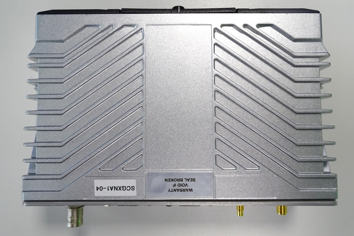
XX6SCG2228M
Jan 28, 2026TETRA RADIO CONTROL SYSTEM
Equipment Class
DSS - Part 15 Spread Spectrum Transmitter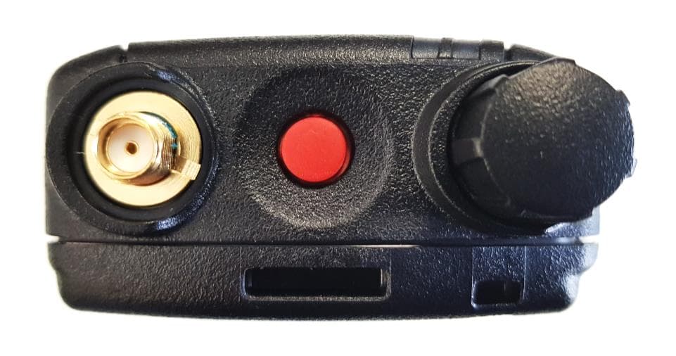
XX6SC2028W
Oct 18, 2021TETRA Portable Terminal with Bluetooth and WLAN
Equipment Class
TNE - Licensed Non-Broadcast Transmitter Held to Ear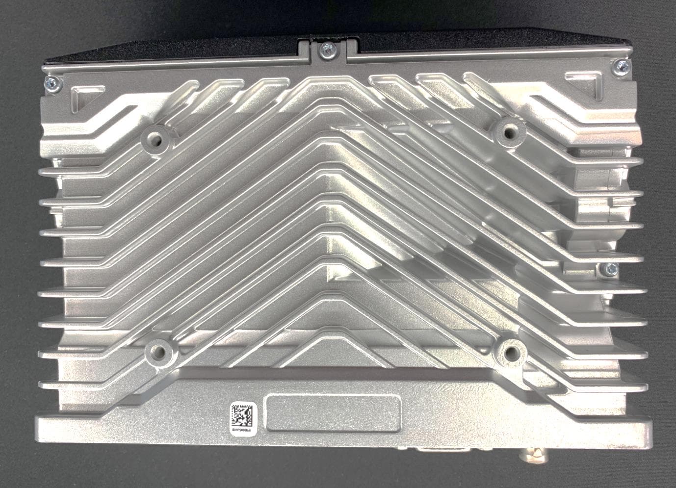
XX6SCG2229W
Apr 15, 2021TETRA Mobile Terminal
Equipment Class
DTS - Digital Transmission System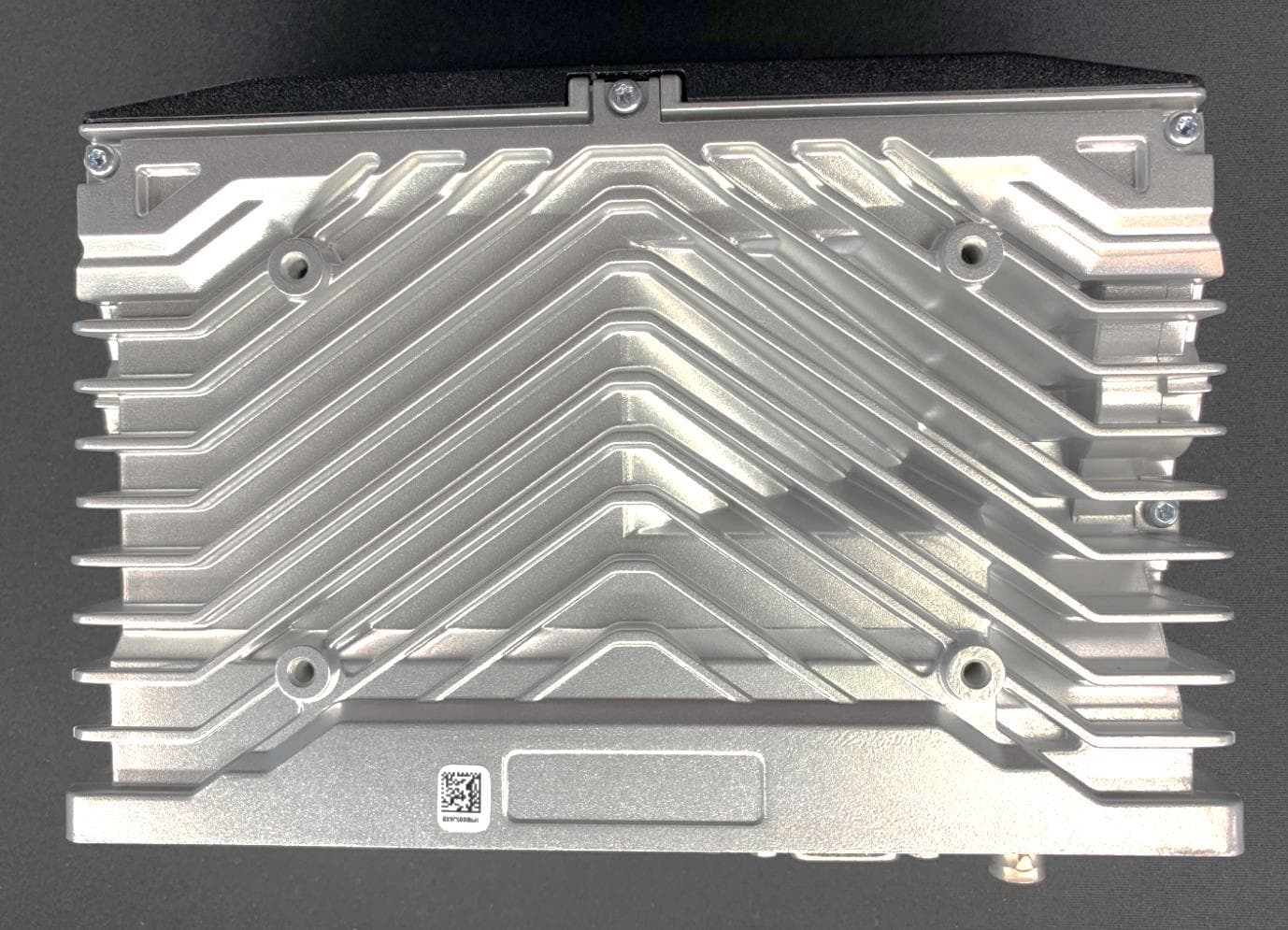
XX6SCG2229
Aug 19, 2020TETRA Mobile Terminal
Equipment Class
DSS - Part 15 Spread Spectrum Transmitter
XX6SC2124
Apr 15, 2020TETRA Portable Handheld Terminal
Equipment Class
DSS - Part 15 Spread Spectrum Transmitter