XX6SEM8040HDMR Mobile Radio
Sepura Limited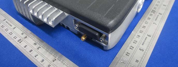
Click to zoom
Application Details
- Equipment Class
- TNB - Licensed Non-Broadcast Station Transmitter
- Date of Grant
- Sep 24, 2014
- Application Purpose
- Original Equipment
- Date of Application
- Sep 24, 2014
- Equipment Note
- DMR Mobile Radio
- Frequency Range
- 406.10000000 - 470.00000000
- Company
- Sepura Limited
- Country
- United Kingdom
Documents & Files
Document Text
Text extracted from the exhibit documents filed with the FCC. Open a document above to read the original.
Users Manual
SEM8040H DMR Mobile Vehicle Installation Guide This Installation Guide provides basic instructions for installing the DMR mobile transceiver into a vehicle. This product can be installed into various makes and models of vehicles and therefore this is not intended to be a definitive guide to installing the product. Always read the vehicle manufacturer’s handbook before starting to install the product. Installation of this product may affect the vehicle electrical systems. Contact the vehicle manufacturer if you are not certain if it is safe to install this product. The installation should comply with FCS1362 CODE OF PRACTICE for the installation of mobile radio and related ancillary equipment in land based vehicles (see http://www.fcs.org.uk). SPR-DOC-03806/1 Original Instructions: ENGLISH © Sepura plc. 2014 Sepura’s policy is to continually improve its products. The features and facilities described in this document were correct at publication, but are subject to change without notice. DMR Mobile 1 Unpacking (1) DMR Mobile (2) Fist microphone (3) Mounting bracket (4) Microphone hanger (5) Fuse (spare) (6) DC power cable including fuse holder and fuse (7) ST4.8x20 self-tapping screw (6 pieces) (8) ST4x16 self-tapping screw (2 pieces) (9) Knurled knob lock screw (2 pieces) Unpack the contents of the box and ensure that all items are received in good condition. If any of the goods are damages or not supplied, notify your Service Provider within 10 days of receipt of equipment. Vehicle Installation Guide 2 Connectors (1) Antenna connector (2) Power cable connector (3) GPS antenna connector (4) Interface connector Safety This product may affect public broadcast radio, security code alarm systems and some engine management systems. The installation of this transceiver must be performed by a qualified vehicle installation technician. This product must be installed in accordance with national and local radio communications authorities and/or Health and Safety regulations. Always switch off the transceiver in environments where RF wireless devices could potentially cause an explosion. Potentially hazardous areas are not always signed. Obey all signs and instructions relating to the usage of RF wireless devices. Do not attempt to dismantle this product. In order to reduce the risk of RF burns, the antenna must always remain connected whilst the equipment is switched on. Under no circumstances should the antenna be connected or disconnected whilst the equipment is switched on. Do not touch the antenna when the transceiver is switched on. Do not touch the heatsink fins when the transceiver is switched on. There is a potential risk of a burn injury. If a non-approved accessory is fitted, it may compromise the product safety ratings and may void any product warranty. It is recommended that the vehicle battery is disconnected before installing the product. Always read the vehicle handbook to establish whether it is practical to DMR Mobile 3 disconnect the vehicle battery without effecting devices, such as central locking mechanisms, engine management computers, security-coded in-car entertainment units and so on. Prolonged operation of the product when the vehicle engine is switched off could drain the vehicle battery. Avoid damage to fuel lines, hydraulic lines and existing cables. This product is suitable for 12V negative earth vehicles only. Do not use other supply systems, this may damage the product. 12V supply leads, antenna cables and speaker wiring must be routed away from gas or fuel lines, and any in-vehicle electrical wiring to reduce the risks associated with a fuel leak. Operator access and safety Install the transceiver in a position where the operator has easy access to the controls and the microphone when wearing a seat belt. The controls must be within the operator's normal field of vision. Position the transceiver so that it does not obstruct or become at risk of damage from any occupant or carried items. Installation Precautions RF energy Vehicle manufacturers make use of electronic control systems such as the ignition and anti-skid devices. Speed control, fuel injection, anti-lock braking, navigation, air bag and other electronic systems are not adversely effected by RF interference. However, if difficulty is experienced or faulty operation suspected, contact the vehicle manufacturer for advice before continuing to install the product. To prevent interference with any other electronic systems in the vehicle, the antenna must be mounted away from these devices and their associated cables. Refer to the vehicle handbook for the location of these devices and information relating to radio frequency interference. Specialised vehicles The installation on certain specialised vehicles such as fuel tankers and fire-fighting vehicles may be subject to additional safety regulations which must be closely observed. Before starting to install this product, check the relevant safety regulations for the vehicle and you understand them. Petrol powered vehicles Check the vehicle to ensure that there are no petrol leaks before starting an installation involving the use of electric tools that may ignite the fuel. Before drilling, always check the location of fuel lines and electrical wiring looms, Avoid drilling near the fuel tank. Vehicle Installation Guide 4 Gas powered vehicles Check the vehicle to ensure that there are no gas leaks before starting an installation involving the use of electric tools that may ignite the fuel. DO NOT USE A NAKED FLAME. Butane and propane gases are heavier than air, and may be present in some lower parts of the vehicle and undetectable by smell. STOP if you notice any sign of a gas leak and inform the vehicle owner immediately. Before drilling, always check the location of fuel lines and electrical wiring looms, Avoid drilling near the fuel tank. Supply cables should be run, if possible, on the opposite side of the vehicle to the gas fuel pipe. Vehicles fitted with elec…
Text truncated - open the document above for the full version.
Users Manual
S M8040H Quick Reference Guide DMR Mobile Radio E Quick Reference Guide 1 General This guide covers the basic operati on of the DMR Mobile. Please refer to the DMR Mobile user guide for more detailed information on using this product. Disclaimer notice Sepura’s policy is to continually im prove its products. The features and facilities described in this document were correct at publication, but are subject to change without notice. Contact Us Sepura plc. Radio House, St Andrew’s Road, Cambridge CB4 1GR United Kingdom Tel: +44 (0)1223 876000 Fax: +44 (0)1223 879000 SPR-DOC-03808/1 Original Instructions: ENGLISH © Sepura plc. 2014 All rights reserved. This document is intended for the use of Sepura plc’s customers and/or other parties only for the purposes of the agr eement or arrangement under which this document is submitted, and no part of it ma y be reproduced or transmitted in any form or means without the prior written permission of Sepura plc. Contents Safety ....................................................................................... 2 Disposing of this product ......................................................... 4 Connectors, controls, buttons and keys ..................................... 6 Status indicators and icons ........................................................ 6 Accessory information .............................................................. 8 Fist microphone ..................................................................... 8 Basic operation ......................................................................... 8 Power On/Off ........................................................................ 8 Adjusting the volume .............................................................. 8 Selecting a Channel ................................................................ 8 Making a PTT call ................................................................. 8 Receiving a PTT call .............................................................. 9 Emergency alarm ................................................................... 9 DMR Mobile Radio 2 Safety Read these safety instructions carefully. Attention! Sepura mobiles are designed for use by mobile workforces, often working alone, and are intended for use in occupational and controlled conditions. This product is restricted for occupational use and is not intended or authorised for use by the general population. It is the responsibility of the person operating the product to ensure that it is operated safely at all times, and that local laws and regulations governing the usage of Radio Freque ncy (RF) products are observed. Users must be trained to operate this product safely. Their personal safety could be affected if they do not understand how to operate this product correctly. Exposure to RF energy Sepura designs and manufactures products to meet strict guidelines and international standards relating to Radio Frequency energy and the potential health risks associated with using such products. Sepura terminals are low powered radio transmitters and receivers that receive and transmit Radio Frequenc y (RF) signals when switched on. The antenna radiates RF energy only when transmitting and not in standby mode. Users should be informed of the poten tial health risks associated with long term exposure to RF energy by their employer. RF energy interference with electronic equipment Some personal medical devices, such as hearing aids and pacemakers, can be affected by RF energy. Alwa ys consult your Service Provider or the manufacturer of the medical device before using RF wireless devices. Some electronic devices are sensitive to RF energy. Always obey signs restricting the use of wireless devices. Safely operating the product Users should always ensure that the mobile is operating correctly before entering any environment that has a potential risk to personal safety. Operate the fist microphone in a vertical position and with the microphone 5 cm (2 in.) away from your mouth when transmitting. Safety in hazardous environments Always switch off the mobile in environments where RF wireless devices could potentially cause an explosion. Potentially hazardous areas are not always signed. Obey al l signs and instructions relating to the usage of RF wireless devices. Do not use the mobile in the presence of gas fumes, explosives dust situations, nuclear facilities, fuel or chemical transfer or storage facilities. This mobile is not designed for use in potentially explosive environments where RF wireless devices could potentially cause an explosion. SWITCH OFF the mobile if you are unsure if the mobile is a risk in these environments. Po tentially hazardous areas are not always signed. Obey all signs and in structions relating to the usage of RF wireless devices. Safety when driving a vehicle Always obey local laws and regula tions governing the operation of RF wireless devices when driving and whilst at locations. Do not operate the product if it creates a distraction from driving safely and observing road conditions. Always switch off the mobile at re fuelling stations. Always observe and obey warning signs relating to th e use of RF wireless devices in the vicinity of refuelling stations. Accessories Sepura products have been tested to meet strict guidelines for personal safety and operational conditions. Only accessories approved by Sepura are recommended for use with this product. set forth for a controlled Quick Reference Guide 3 Always read the instructions supplie d with the accessory for additional safety instructions. Unauthorised modifications to the product could cause the product to become non-operational. The use of non-approved accessories may invalidate any product warranty. If a non-approved accessory is fitted, it may compromise the product safety ratings. Servicing Do not attempt to dismantle this product. Servicing and repairs to this produc t must be performed by trained service tech…
Text truncated - open the document above for the full version.
Cover Letter(s)
QA-FR-170-B
External Photos
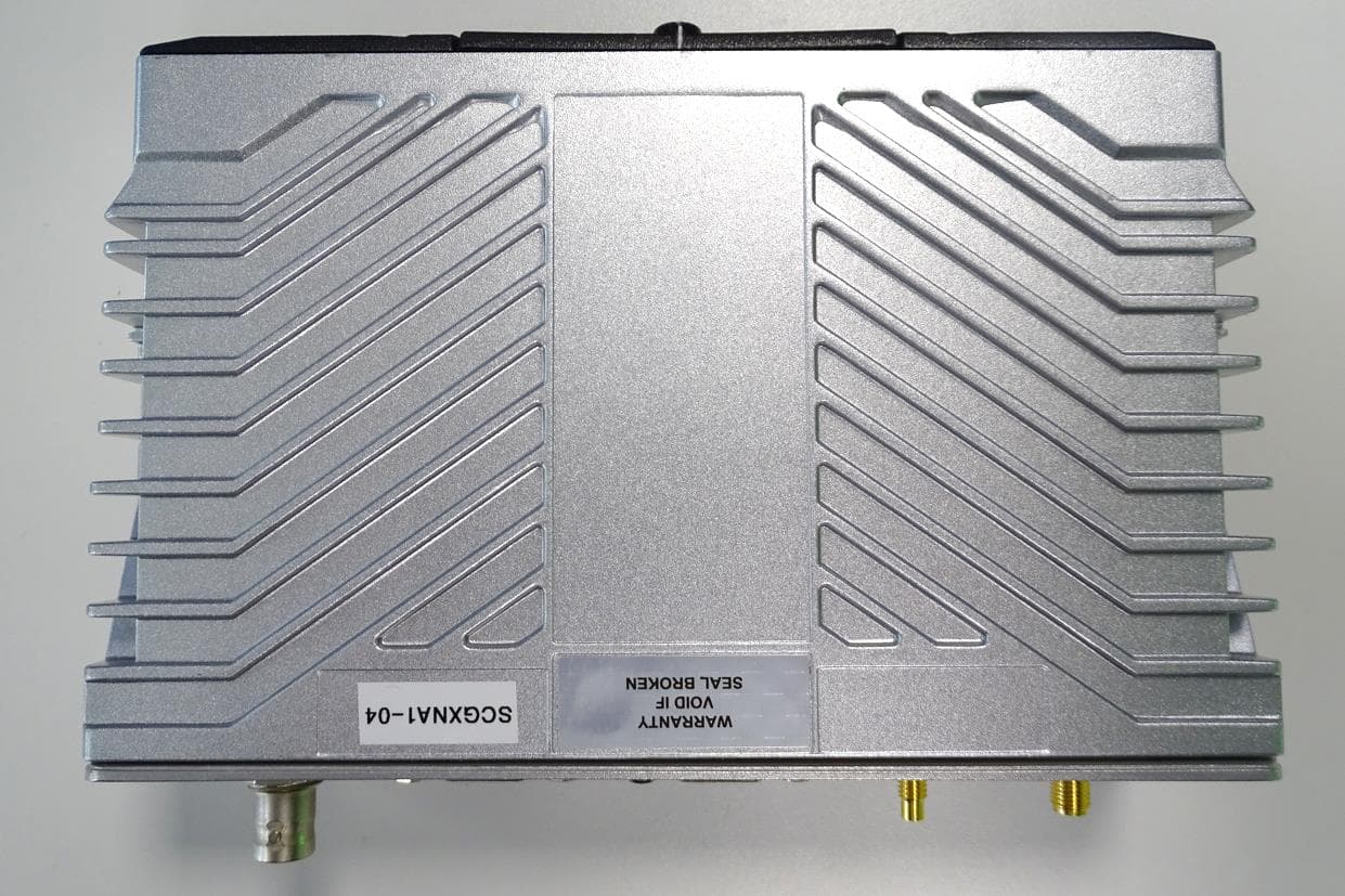
EXHIBIT B - EUT EXTERNAL PHOTOGRAPHS EUT – All View EUT –Top View EUT – Bottom View EUT – Left Side View EUT – Right Side View EUT – Front Side View EUT – Rear Side View
ID Label/Location Info
EXHIBIT A - FCC ID LABELING AND LOCATION FCC ID Label FCC ID Label Location The label shown shall be permanently affixed at a conspicuous location on the device and be readily visible to the user at the time purchase (Labeling requirements per 2.925) Label here
Internal Photos
EXHIBIT C - EUT INTERNAL PHOTOGRAPHS EUT – Front Cover Off View EUT – Front Cover Off View EUT – Uncover View EUT – Back Cover Off View EUT – Cover Off View EUT – Main Board Top With Shielding View EUT – Main Board Top Without Shielding View EUT – Main Board Bottom With Shielding View EUT – Main Board Bottom Without Shielding View EUT – Uncover View EUT – Sub Board Uncover View EUT – Sub Board Top View EUT – Sub Board Bottom View EUT – Front Uncover View EUT – Front Cover Off View EUT – Display Board Top View EUT – Display Board Bottom View EUT – Base View EUT – Base View EUT – Base View EUT of Hand Microphone – Uncover View EUT of Hand Microphone – Button Board Top View EUT of Hand Microphone – Button Board Bottom View EUT of Hand Microphone – Sub Board Top View EUT of Hand Microphone – Sub Board Bottom View
RF Exposure Info
Bay Area Compliance Laboratories Corp. (Dongguan) Report No.: R2DG131112005-00 FCC Part 22 and 90 Page 8 of 46 FCC §2.1091- MAXIMUM PERMISSIBLE EXPOSURE (MPE) Applicable Standard According to 1.1310, systems operating under the provisions of this section shall be operated in a manner that ensures the public is not exposed to RF energy level in excess of the communication guidelines. Limits for Occupational/Controlled Exposure Frequency Range (MHz) Electric Field Strength (E) (V/m) Magnetic Field Strength (H) (A/m) Power Density (S) (mW/cm 2 ) Averaging Time |E|, |H| or S (minutes) 0.3- 3.0 614 1.63 (100)* 6 3.0 - 30 1842/f 4.89/f (900/f 2 )* 6 30-300 61.4 0.163 1.0 6 300-1500 / / f/300 6 1500-100,000 / / 5 6 f = frequency in MHz * = Plane-wave equivalent power density MPE Calculation Predication of MPE limit at a given distance S = PG/4πR 2 Where: S = power density (in appropriate units, e.g. mW/cm 2 ); P = power input to the antenna (in appropriate units, e.g., mW); G = power gain of the antenna in the direction of interest relative to an isotropic radiator R = distance to the center of radiation of the antenna (appropriate units, e.g., cm); Frequency Output Power Cable Loss Typical Antenna Distance Power Density Power Density Limit MHz mW Duty Cycle dB numericdBinumeric cm mW/m 2 mW/m 2 435 44668 50% 2 1.58 0 1 75 0.2 1.45 Note: the target power is 46dBm +/-0.5dB. Result: Pass
Test Report
Note: This test report is prepared for the customer shown above and for the device described herein. It may not be duplicated or used in part without prior written consent from Bay Area Compliance Laboratories Corp. This report must not be used by the customer to claim product certification, approval, or endorsement by NVLAP*, or any agency of the Federal Government. * This report may contain data that are not covered by the NVLAP accreditation and shall be marked with an asterisk “★” (Rev.2), This report is valid only with a valid digital signature. The digital signature may be available only under the Adobe software above version 7.0. FCC PART 22 and 90 TEST REPORT For Sepura plc Radio House, St. Andrews Road, Cambridge CB4 1GR UK FCC ID: XX6SEM8040H Report Type: Original Report Product Type: DMR Mobile Radio Test Engineer: Leon Chen Report Number: R2DG131112005-00 Report Date: 2014-08-21 Reviewed By: Jerry Zhang EMC Manager Test Laboratory: Bay Area Compliance Laboratories Corp. (Dongguan) No.69 Pulongcun, Puxinhu Industrial Zone, Tangxia, Dongguan, Guangdong, China Tel: +86-769-86858888 Fax: +86-769-86858891 www.baclcorp.com.cn Bay Area Compliance Laboratories Corp. (Dongguan) Report No.: R2DG131112005-00 FCC Part 22 and 90 Page 2 of 46 TABLE OF CONTENTS GENERAL INFORMATION.......................................................................................................................................4 PRODUCT DESCRIPTION FOR EQUIPMENT UNDER TEST (EUT) ....................................................................................4 OBJECTIVE...................................................................................................................................................................4 RELATED SUBMITTAL(S)/GRANT(S).............................................................................................................................4 TEST METHODOLOGY..................................................................................................................................................4 TEST FACILITY.............................................................................................................................................................5 SYSTEM TEST CONFIGURATION ..........................................................................................................................6 DESCRIPTION OF TEST CONFIGURATION......................................................................................................................6 SUPPORT EQUIPMENT LIST AND DETAILS....................................................................................................................6 BLOCK DIAGRAM OF TEST SETUP................................................................................................................................6 SUMMARY OF TEST RESULTS...............................................................................................................................7 FCC §2.1091- MAXIMUM PERMISSIBLE EXPOSURE (MPE) ...........................................................................8 APPLICABLE STANDARD..............................................................................................................................................8 FCC §2.1046 &§ 22.727 & §90.205- RF OUTPUT POWER ....................................................................................9 APPLICABLE STANDARD..............................................................................................................................................9 TEST PROCEDURE........................................................................................................................................................9 TEST EQUIPMENT LIST AND DETAILS...........................................................................................................................9 TEST DATA..................................................................................................................................................................9 FCC §2.1047 & §90.207 - MODULATION CHARACTERISTIC ..........................................................................11 APPLICABLE STANDARD............................................................................................................................................11 TEST PROCEDURE......................................................................................................................................................11 TEST EQUIPMENT LIST AND DETAILS.........................................................................................................................11 TEST DATA................................................................................................................................................................11 FCC §2.1049& §22.357 & § 22.731 &§90.209 & §90.210 – OCCUPIED BANDWIDTH & EMISSION MASK15 APPLICABLE STANDARD............................................................................................................................................15 TEST EQUIPMENT LIST AND DETAILS.........................................................................................................................16 TEST PROCEDURE......................................................................................................................................................16 TEST DATA................................................................................................................................................................16 FCC §2.1051 & §22.861 & §90.210 - SPURIOUS EMISSIONS AT ANTENNA TERMINALS ..........................25 APPLICABLE STANDARD............................................................................................................................................25 TEST EQUIPMENT LIST AND DETAILS..........................................................................................…
Text truncated - open the document above for the full version.
Test Setup Photos
EXHIBIT D - TEST SETUP PHOTOGRAPHS Radiated Emission View (Below 1 GHz) Radiated Emissions View (Above 1 GHz)
Contact Information
Applicant
Chris Beecham(Conformance Engineer)
Test Firm
Bay Area Compliance Laboratories Corp. (Dongguan)John Chan
[email protected]86-769-86858888
Technical Specifications
| # | Rule Parts | Frequency Range | Power Output | Emission | Tolerance |
|---|---|---|---|---|---|
| 6 | 22,9 | 406.1 MHz - 470 MHz | 40 W | 9K60FXW | 0.35 ppm |
Other Applications from Sepura Limited
XX6SCG2228M
Jan 28, 2026TETRA RADIO CONTROL SYSTEM
Equipment Class
DSS - Part 15 Spread Spectrum Transmitter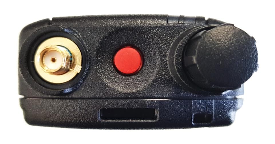
XX6SC2028W
Oct 18, 2021TETRA Portable Terminal with Bluetooth and WLAN
Equipment Class
TNE - Licensed Non-Broadcast Transmitter Held to Ear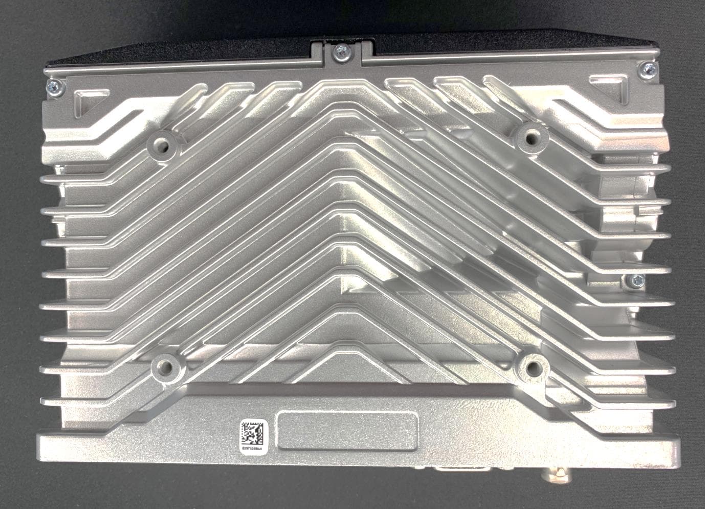
XX6SCG2229W
Apr 15, 2021TETRA Mobile Terminal
Equipment Class
DTS - Digital Transmission System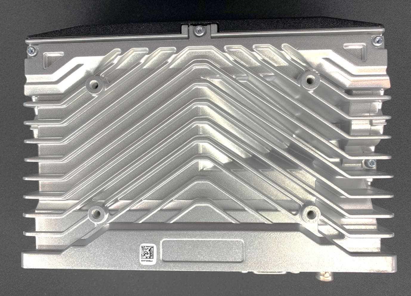
XX6SCG2229
Aug 19, 2020TETRA Mobile Terminal
Equipment Class
DSS - Part 15 Spread Spectrum Transmitter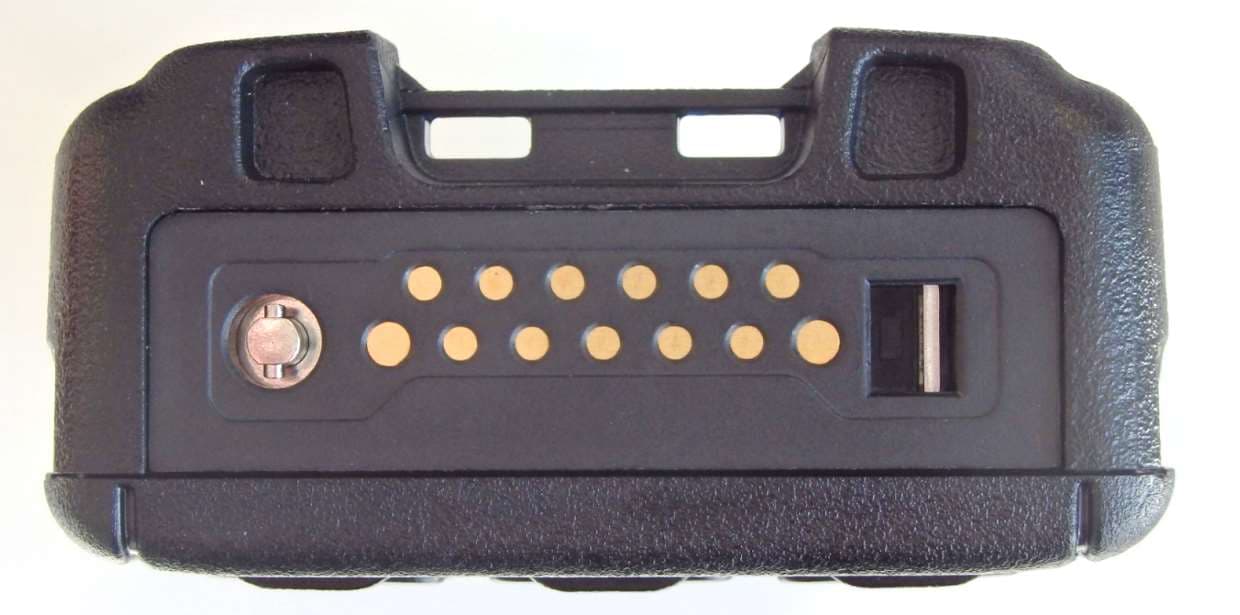
XX6SC2124
Apr 15, 2020TETRA Portable Handheld Terminal
Equipment Class
DSS - Part 15 Spread Spectrum Transmitter