XX6STP8280Portable TETRA Radio
Sepura Limited
Click to zoom
Application Details
- Equipment Class
- JBP - Part 15 Class B Computing Device Peripheral
- Date of Grant
- Nov 02, 2011
- Application Purpose
- Original Equipment
- Date of Application
- Nov 02, 2011
- Equipment Note
- Portable TETRA Radio
- Company
- Sepura Limited
- Country
- United Kingdom
Documents & Files
Document Text
Text extracted from the exhibit documents filed with the FCC. Open a document above to read the original.
Users Manual
STP8000 Series CAR KIT INSTALLATION & USER GUIDE 1 sepura INTRODUCTION The STP8000 car kit provides secure retention of the radio within a cradle. The car kit features battery charging, external antenna connection, external PTT keypad, hands-free operation with the external microphone and loudspeaker. A standard RS232 data port and USB is provided for data transfer applications. Connections are provided for optional accessories. Cable colour Electrical parameters Fuse RED Vehicle +ve (12v MAX) 4 Amp BLACK Vehicle –ve (vehicle chassis) n/a PINK Open drain Output, max current 0.5A Protected by a re-settable fuse provided inside car kit YELLOW Open drain Output, max current 0.5A Protected by a re-settable fuse provided inside car kit BLUE Input Signal Level 12VDC (200 uA max) 1 Amp sepura or MICSMICALARMPTT REMOTE PTT CRADLE Front INTERFACE UNIT (user interface) USBDATA (RS232)SXC HANDSET/FIST MIC Loudspeaker Output 50Ω Rear INTERFACE UNIT (vehicle harness) Antenna Connections for accessories STP8000 Series CAR KIT INSTALLATION & USER GUIDE 2 sepura Information The STP8000 car kit is designed for 12 V negative earth systems. In vehicles with a 24 V supply, an approved converter must be used, NOT a 12 V tap on the battery. The equipment is to be installed in accordance with the requirements of local radio communications authorities and/or Health and Safety regulations. 12 V supply leads, antenna cables and speaker wiring is to be routed as far away as possible from gas or fuel lines. This reduces the risk to safety in the event of a leak. The car kit should be positioned so that it does not obstruct, or become at risk of damage from, any occupant or carried items. All cabling should be hidden and not left loose. Radio Software For correct operation of the STP8000 with the car kit, the STP8000 must have radio software of v9.0 greater. INSTALLATION This installation guide provides basic installation information and is not intended to be definitive, as different types of vehicles will require different ways installation arrangements. The installer must ensure that fixing screws of an appropri- ate length are used (some installations may require different screws). The information given here is general and for guid- ance only. The installation must comply with in-country CODE OF PRACTICE for the installation of mobile radio and related ancillary equipment in land based vehicles — e.g. FCS1362 (formally MPT1362)see http:// www.fcs.org.uk. WARNING 1 Disconnect the vehicle’s battery before commencing installation (be aware of effect on public broadcast radio security code, alarm systems and some engine man- agement systems). 2 Do not smoke, or use naked flames, when working near the vehicle’s fuel system. 3 Ensure that fuel lines, hydraulic lines and existing cables are not damaged during installation. 4 Ensure that the installation does not impede the normal operation of the vehicle, including the operation of any safety device, e.g., airbags and seatbelt tensioners. 5 Speed control, fuel injection, anti-lock braking, naviga- tion, air bag and other electronic systems are relatively immune to RF interference. However, if difficulty is experienced, or faulty operation suspected, consult the vehicle’s dealer. 6 This equipment is suitable for 12 V negative earth vehi- cles only. Use on other supply systems will result in damage to the equipment. 7 No part of the equipment should be mounted such that injury to the occupants is likely during an accident. 8 Prolonged operation of the radio in the car kit with the vehicle engine switched off, could drain the vehicle’s battery. 9 Prolonged operation at high volume levels may cause the interface unit to become hot. Cradle The cradle should be attached to the vehicle’s interior in a convenient position using the mounting brackets. The location of the cradle should allow the user unrestricted access to the radio’s controls. The radio’s display should be visible to the user but not distracting when driving. The cradle should not prevent the user from controlling or operating the vehicle. Interface Unit Attach the interface unit to the vehicle’s interior, using, if appropriate, the four 25mm self-tapping screws provided. The interface unit should be mounted on a firm surface in- side the passenger compartment, within reach of all cabling. The data socket should be easily accessible. Connect the lead from the cradle to the socket labelled “RADIO”. Con- nect the vehicle harness to the socket labelled “AUTO”. Note: Do not install the interface unit in engine compartment. Cables & Connectors Ensure the cables due not rub against sharp edges and are not subjected to undue stress. Power Connection (thick red and black wires) • The positive power line must include a fuse as close as possible to the power source. The negative power line must be connected close to the battery-to-vehicle-body connexion (not directly to the battery) and must not include a fuse. • It is recommended that the power cable runs are kept as short as possible. • The blue wire provides an ignition sensing input. If ignition switching is required, trim the wire to length so that it can be wired, via a fuse, to the ignition switch, using the splicing connector provided. Otherwise this wire must be connected, via a fuse, to the permanent positive supply. A fuse must always be fitted close to where the wire is connected. Fuse Ratings Positive supply 4 A Ignition sense 1 A The ring terminated wires are for direct connection to the vehicle battery (do not connect at this stage); supply should not be taken from any other point. Feed the bullet terminated free ends through the bulkhead, using a grommet to protect the wires. Locate the free ends under the dashboard and connect to the main wiring har- ness supplied with the car kit. Connect the ring terminals to the vehicle battery when the rest of the installation (see fol- lowing sections) is complete and satisfactory. Remote Microphone The remote microp…
Text truncated - open the document above for the full version.
Block Diagram
sepura STP8280 Circuit Description (All frequency bands above 800MHz) 1. Introduction The STP series radio control system is built around an Analog Devices base-band digital processor. This is supported by Sepura designed custom integrated circuits acting as analogue and digital-plus-encryption interfacing circuits, to provide both control and base-band digital signal processing functionality for the radio unit. The radio hardware consists of a double conversion receiver and a Cartesian loop based transmitter. Local oscillator feeds (to both) are provided by a fractional-N frequency synthesiser system, locked to a high stability VCTCXO. An optional high sensitivity GPS receiver with integral antenna is incorporated into a module, fitted within the radio. A basic top level block diagram is shown below: 2. Receiver Architecture The receiver employs two discrete band pass filters to provide RF frequency selectivity. Both filters are SAW bandpass filters. The LNA has switchable gain to provide coarse AGC adjustment. An active mixer is used to convert to the IF of circa 70MHz, followed by a crystal filter. The IF IC includes linear gain blocks, with integral AGC facilities and also provides conversion from IF to base-band I and Q Ant Switch Cartesian loo p system Receiver LNA &BPF Receiver IF system Base- band interface system Control system Audio Amp Frequency Synthesiser System Ref VCTCXO GPS Module Accessory Connector Facility Connector PA MMI sepura outputs. These are connected to the Base-band interface circuitry. AGC is controlled via the processor and base-band interface circuitry. 3. Transmitter Architecture The transmitter uses a Cartesian feedback loop to achieve the power amplifier linearity necessary to meet the requirements of the Tetra specifications. The diagram below illustrates the Cartesian feedback loop concept in its simplest form: Negative feedback is applied in phase quadrature to dramatically enhance the overall transmitter linearity. The phase adjust control ensures that the feedback is always negative. The implementation of the Cartesian loop, involves the use of an integrated Cartesian loop IC operating at the final carrier frequency. The injection signal from the frequency synthesiser is at 2 times the carrier frequency. This is illustrated in the diagram below. Base-band I and Q signals - - Phase adjust Quadrature Mixers Quadrature Mixers Linear Amplifiers Directional coupler Negative feedback I and Q signals Programmable attenuators for power level adjustment LO from synthesiser s ystem BPF LNA BPF AGC control I To Interface Cct Q RX LO1 Ref 14.4MHz Linear IF s ystem Channel Filter Tuning control sepura Quadrature I and Q base-band signals are applied to the integrated Cartesian loop system. The Cartesian loop IC provides a forward path signal which is then amplified in a discrete linear amplifier chain. The amplified signal is then routed through the directional coupler, antenna switch and a low pass harmonic filter, to the antenna. The output taken from the directional coupler is a reduced power level replica of the actual transmitted signal. This is attenuated, filtered and then applied as the feedback to the Cartesian loop IC. Injection signals to the Cartesian loop are provided via a divide by 2 circuit (within the Cartesian loop IC) by the frequency synthesiser system. Power level changes are achieved by changes in the programmable attenuators incorporated within the Cartesian loop IC, programmed via the control system. 4. Frequency Synthesiser Architecture The frequency synthesiser system uses a pair of synthesiser ICs one for the transmitter and one for the receiver. The synthesisers use fractional-N divider techniques to provide a short locking time in combination with low adjacent channel phase noise levels. A reference voltage controlled temperature compensated crystal oscillator (VCTCXO) operating at 14.4MHz acts as the master reference for both synthesisers and the radio control system. Inherent frequency stability of the VCTCXO is better than 1 part per million. During trunked network operation, this reference is frequency locked to the received base station frequency. Cartesian loop system from the base-band interface circuitry I and Q in puts Directional coupler Ant. switch LPF BPF To Receiver TX LO PA sepura 4.1 Receiver Frequency Synthesiser The local oscillator signal (RX LO)1 is at carrier frequency plus IF frequency A 14.4MHz reference signal (fed to a synthesiser on-board the receiver IF IC) enables conversion of the IF signal to base-band I and Q quadrature components. 4.2 Transmitter Frequency Synthesiser The transmitter VCO and synthesiser operate at 2/3 of final frequency. The VCO output is buffered then fed both to the synthesiser IC and to a frequency tripler circuit. The following filter passes the tripled frequency and suppresses unwanted harmonics of the VCO frequency. The local oscillator signal (TX LO) at 4 times carrier frequency is then amplified and injected into the transmitter Cartesian loop IC. 5. Base-band and control hardware VCO Loop filter Synthesiser Reference 14.4MHz VCTCXO RX LO1 IF IC 14.4MHz Tune voltage Serial control VCO (4/3 final frequency) Loop Filter Synthesiser Tripler Serial control 14.4MHz BP Filter TX LO sepura The core of the control and base-band circuitry is a highly integrated base-band digital processor. This is supported by analogue and digital base-band port custom integrated circuits. Functionality in this section includes: CPU DSP Error correction and digital baseband filtering High performance A/D and D/A functions for both RF and audio interfaces Support for TEA encryption Support for Smart Card interface Support for Micro SD card interface Support for end-to-end encryption Real time clock Interfaces to other radio sub-systems Memory is provided by 32MB of Flash and 8MB of PSRAM. 6. Optional GPS Module The GPS module incorporates RF and signal processing circuitry on a single …
Text truncated - open the document above for the full version.
Cover Letter(s)
Sepura plc Radio House, St Andrew’s Road, Cambridge CB4 1GR, UK Tel: +44 (0) 1223 876000 Fax: +44 (0) 1223 879000 www.sepura.com Sepura plc Registered in England No: 4353801 Registered office: Radio House, St Andrew’s Road, Cambridge CB4 1GR, England. Date 11 th July 2011 BABT TCB Forsyth House, Churchfield Road, Walton-on-Thames, Surrey, KT12 2TD Confidentiality Request Pursuant to Sections 0.457(d)(1)(ii) and 0.459 of the Commission’s Rules, Sepura plc hereby requests permanent confidential treatment of information accompanying this application as outlined below: BOM’s Circuit Diagrams Circuit Descriptions Operating Descriptions Block Diagrams The above materials contain trade secrets and proprietary information not customarily released to the public. The public disclosure of these matters might be harmful to the Applicant and provide unjustified benefits to its competitors. The Applicant understands that pursuant to Rule 0.457(d)(1)(ii), disclosure of this Application and all accompanying materials will not be made before the date of the Grant for this Application. Yours sincerely, Company Officer: Bob Allen Telephone Number: +44 (0) 1223 876000 Email: [email protected]
External Photos
Sepura plc Radio House, St Andrew’s Road, Cambridge CB4 1GR, UK Tel: +44 (0) 1223 876000 Fax: +44 (0) 1223 879000 www.sepura.com Page 1 of 8 Sepura plc Registered in England No: 4353801 Registered office: Radio House, St Andrew’s Road, Cambridge CB4 1GR, England. External Photographs For XX6 STP8280 Sepura STP8280 800MHz Tetra Handportable Sepura plc Radio House, St Andrew’s Road, Cambridge CB4 1GR, UK Tel: +44 (0) 1223 876000 Fax: +44 (0) 1223 879000 www.sepura.com Page 2 of 8 Sepura plc Registered in England No: 4353801 Registered office: Radio House, St Andrew’s Road, Cambridge CB4 1GR, England. Contents STP8280 Tetra Handportable External ........................................................................................ 3 Front Cover .................................................................................................................................................. 3 Rear Cover ................................................................................................................................................... 4 RAC Side ...................................................................................................................................................... 5 PTT Side ....................................................................................................................................................... 6 FAC Socket .................................................................................................................................................. 7 Top ................................................................................................................................................................ 7 STP8280 Antenna .......................................................................................................................... 8 Part Number 300 00498 STP8280 Whip Antenna ..................................................................................... 8 Sepura plc Radio House, St Andrew’s Road, Cambridge CB4 1GR, UK Tel: +44 (0) 1223 876000 Fax: +44 (0) 1223 879000 www.sepura.com Page 3 of 8 Sepura plc Registered in England No: 4353801 Registered office: Radio House, St Andrew’s Road, Cambridge CB4 1GR, England. STP8280 Tetra Handportable External XX6 STP8280 Front Cover Sepura plc Radio House, St Andrew’s Road, Cambridge CB4 1GR, UK Tel: +44 (0) 1223 876000 Fax: +44 (0) 1223 879000 www.sepura.com Page 4 of 8 Sepura plc Registered in England No: 4353801 Registered office: Radio House, St Andrew’s Road, Cambridge CB4 1GR, England. XX6 STP8280 Rear Cover Sepura plc Radio House, St Andrew’s Road, Cambridge CB4 1GR, UK Tel: +44 (0) 1223 876000 Fax: +44 (0) 1223 879000 www.sepura.com Page 5 of 8 Sepura plc Registered in England No: 4353801 Registered office: Radio House, St Andrew’s Road, Cambridge CB4 1GR, England. XX6 STP8280 RAC Side Sepura plc Radio House, St Andrew’s Road, Cambridge CB4 1GR, UK Tel: +44 (0) 1223 876000 Fax: +44 (0) 1223 879000 www.sepura.com Page 6 of 8 Sepura plc Registered in England No: 4353801 Registered office: Radio House, St Andrew’s Road, Cambridge CB4 1GR, England. XX6 STP8280 PTT Side Sepura plc Radio House, St Andrew’s Road, Cambridge CB4 1GR, UK Tel: +44 (0) 1223 876000 Fax: +44 (0) 1223 879000 www.sepura.com Page 7 of 8 Sepura plc Registered in England No: 4353801 Registered office: Radio House, St Andrew’s Road, Cambridge CB4 1GR, England. XX6 STP8280 FAC Socket Top Sepura plc Radio House, St Andrew’s Road, Cambridge CB4 1GR, UK Tel: +44 (0) 1223 876000 Fax: +44 (0) 1223 879000 www.sepura.com Page 8 of 8 Sepura plc Registered in England No: 4353801 Registered office: Radio House, St Andrew’s Road, Cambridge CB4 1GR, England. STP8280 Antenna XX6 STP8280 Part Number 300 00498 STP8280 Whip Antenna
Internal Photos
Sepura plc Radio House, St Andrew’s Road, Cambridge CB4 1GR, UK Tel: +44 (0) 1223 876000 Fax: +44 (0) 1223 879000 www.sepura.com Page 1 of 11 Sepura plc Registered in England No: 4353801 Registered office: Radio House, St Andrew’s Road, Cambridge CB4 1GR, England. Internal Photographs For XX6 STP8280 Sepura STP8280 800MHz Tetra Handportable Sepura plc Radio House, St Andrew’s Road, Cambridge CB4 1GR, UK Tel: +44 (0) 1223 876000 Fax: +44 (0) 1223 879000 www.sepura.com Page 2 of 11 Sepura plc Registered in England No: 4353801 Registered office: Radio House, St Andrew’s Road, Cambridge CB4 1GR, England. Contents STP8280 Tetra Handportable Internal .......................................................................................... 3 Rear of Main PCB ........................................................................................................................................ 3 Rear of Main PCB: LCD Frame Removed ................................................................................................. 4 Rear of Main PCB: LCD Side Cans Removed ........................................................................................... 5 Front of Main PCB: GPS Fitted .................................................................................................................. 6 Front of Main PCB: GPS Removed ............................................................................................................ 7 Front of Main PCB: Heatsink Removed .................................................................................................... 8 Front of Main PCB: Cans Removed ........................................................................................................... 9 STP8280 GPS Module ................................................................................................................. 10 GPS Module Top Side: Cans Removed................................................................................................... 10 GPS Module Bottom Side: Cans Removed ............................................................................................ 11 Sepura plc Radio House, St Andrew’s Road, Cambridge CB4 1GR, UK Tel: +44 (0) 1223 876000 Fax: +44 (0) 1223 879000 www.sepura.com Page 3 of 11 Sepura plc Registered in England No: 4353801 Registered office: Radio House, St Andrew’s Road, Cambridge CB4 1GR, England. STP8280 Tetra Handportable Internal XX6 STP8280 Rear of Main PCB Sepura plc Radio House, St Andrew’s Road, Cambridge CB4 1GR, UK Tel: +44 (0) 1223 876000 Fax: +44 (0) 1223 879000 www.sepura.com Page 4 of 11 Sepura plc Registered in England No: 4353801 Registered office: Radio House, St Andrew’s Road, Cambridge CB4 1GR, England. XX6 STP8280 Rear of Main PCB: LCD Frame Removed Sepura plc Radio House, St Andrew’s Road, Cambridge CB4 1GR, UK Tel: +44 (0) 1223 876000 Fax: +44 (0) 1223 879000 www.sepura.com Page 5 of 11 Sepura plc Registered in England No: 4353801 Registered office: Radio House, St Andrew’s Road, Cambridge CB4 1GR, England. XX6 STP8280 Rear of Main PCB: LCD Side Cans Removed Sepura plc Radio House, St Andrew’s Road, Cambridge CB4 1GR, UK Tel: +44 (0) 1223 876000 Fax: +44 (0) 1223 879000 www.sepura.com Page 6 of 11 Sepura plc Registered in England No: 4353801 Registered office: Radio House, St Andrew’s Road, Cambridge CB4 1GR, England. XX6 STP8280 Front of Main PCB: GPS Fitted Sepura plc Radio House, St Andrew’s Road, Cambridge CB4 1GR, UK Tel: +44 (0) 1223 876000 Fax: +44 (0) 1223 879000 www.sepura.com Page 7 of 11 Sepura plc Registered in England No: 4353801 Registered office: Radio House, St Andrew’s Road, Cambridge CB4 1GR, England. XX6 STP8280 Front of Main PCB: GPS Removed Sepura plc Radio House, St Andrew’s Road, Cambridge CB4 1GR, UK Tel: +44 (0) 1223 876000 Fax: +44 (0) 1223 879000 www.sepura.com Page 8 of 11 Sepura plc Registered in England No: 4353801 Registered office: Radio House, St Andrew’s Road, Cambridge CB4 1GR, England. XX6 STP8280 Front of Main PCB: Heatsink Removed Sepura plc Radio House, St Andrew’s Road, Cambridge CB4 1GR, UK Tel: +44 (0) 1223 876000 Fax: +44 (0) 1223 879000 www.sepura.com Page 9 of 11 Sepura plc Registered in England No: 4353801 Registered office: Radio House, St Andrew’s Road, Cambridge CB4 1GR, England. XX6 STP8280 Front of Main PCB: Cans Removed Sepura plc Radio House, St Andrew’s Road, Cambridge CB4 1GR, UK Tel: +44 (0) 1223 876000 Fax: +44 (0) 1223 879000 www.sepura.com Page 10 of 11 Sepura plc Registered in England No: 4353801 Registered office: Radio House, St Andrew’s Road, Cambridge CB4 1GR, England. STP8280 GPS Module XX6 STP8280 GPS Module Top Side: Cans Removed Sepura plc Radio House, St Andrew’s Road, Cambridge CB4 1GR, UK Tel: +44 (0) 1223 876000 Fax: +44 (0) 1223 879000 www.sepura.com Page 11 of 11 Sepura plc Registered in England No: 4353801 Registered office: Radio House, St Andrew’s Road, Cambridge CB4 1GR, England. XX6 STP8280 GPS Module Bottom Side: Cans Removed
Operational Description
sepura STP8280 Circuit Description (All frequency bands above 800MHz) 1. Introduction The STP series radio control system is built around an Analog Devices base-band digital processor. This is supported by Sepura designed custom integrated circuits acting as analogue and digital-plus-encryption interfacing circuits, to provide both control and base-band digital signal processing functionality for the radio unit. The radio hardware consists of a double conversion receiver and a Cartesian loop based transmitter. Local oscillator feeds (to both) are provided by a fractional-N frequency synthesiser system, locked to a high stability VCTCXO. An optional high sensitivity GPS receiver with integral antenna is incorporated into a module, fitted within the radio. A basic top level block diagram is shown below: 2. Receiver Architecture The receiver employs two discrete band pass filters to provide RF frequency selectivity. Both filters are SAW bandpass filters. The LNA has switchable gain to provide coarse AGC adjustment. An active mixer is used to convert to the IF of circa 70MHz, followed by a crystal filter. The IF IC includes linear gain blocks, with integral AGC facilities and also provides conversion from IF to base-band I and Q Ant Switch Cartesian loo p system Receiver LNA &BPF Receiver IF system Base- band interface system Control system Audio Amp Frequency Synthesiser System Ref VCTCXO GPS Module Accessory Connector Facility Connector PA MMI sepura outputs. These are connected to the Base-band interface circuitry. AGC is controlled via the processor and base-band interface circuitry. 3. Transmitter Architecture The transmitter uses a Cartesian feedback loop to achieve the power amplifier linearity necessary to meet the requirements of the Tetra specifications. The diagram below illustrates the Cartesian feedback loop concept in its simplest form: Negative feedback is applied in phase quadrature to dramatically enhance the overall transmitter linearity. The phase adjust control ensures that the feedback is always negative. The implementation of the Cartesian loop, involves the use of an integrated Cartesian loop IC operating at the final carrier frequency. The injection signal from the frequency synthesiser is at 2 times the carrier frequency. This is illustrated in the diagram below. Base-band I and Q signals - - Phase adjust Quadrature Mixers Quadrature Mixers Linear Amplifiers Directional coupler Negative feedback I and Q signals Programmable attenuators for power level adjustment LO from synthesiser s ystem BPF LNA BPF AGC control I To Interface Cct Q RX LO1 Ref 14.4MHz Linear IF s ystem Channel Filter Tuning control sepura Quadrature I and Q base-band signals are applied to the integrated Cartesian loop system. The Cartesian loop IC provides a forward path signal which is then amplified in a discrete linear amplifier chain. The amplified signal is then routed through the directional coupler, antenna switch and a low pass harmonic filter, to the antenna. The output taken from the directional coupler is a reduced power level replica of the actual transmitted signal. This is attenuated, filtered and then applied as the feedback to the Cartesian loop IC. Injection signals to the Cartesian loop are provided via a divide by 2 circuit (within the Cartesian loop IC) by the frequency synthesiser system. Power level changes are achieved by changes in the programmable attenuators incorporated within the Cartesian loop IC, programmed via the control system. 4. Frequency Synthesiser Architecture The frequency synthesiser system uses a pair of synthesiser ICs one for the transmitter and one for the receiver. The synthesisers use fractional-N divider techniques to provide a short locking time in combination with low adjacent channel phase noise levels. A reference voltage controlled temperature compensated crystal oscillator (VCTCXO) operating at 14.4MHz acts as the master reference for both synthesisers and the radio control system. Inherent frequency stability of the VCTCXO is better than 1 part per million. During trunked network operation, this reference is frequency locked to the received base station frequency. Cartesian loop system from the base-band interface circuitry I and Q in puts Directional coupler Ant. switch LPF BPF To Receiver TX LO PA sepura 4.1 Receiver Frequency Synthesiser The local oscillator signal (RX LO)1 is at carrier frequency plus IF frequency A 14.4MHz reference signal (fed to a synthesiser on-board the receiver IF IC) enables conversion of the IF signal to base-band I and Q quadrature components. 4.2 Transmitter Frequency Synthesiser The transmitter VCO and synthesiser operate at 2/3 of final frequency. The VCO output is buffered then fed both to the synthesiser IC and to a frequency tripler circuit. The following filter passes the tripled frequency and suppresses unwanted harmonics of the VCO frequency. The local oscillator signal (TX LO) at 4 times carrier frequency is then amplified and injected into the transmitter Cartesian loop IC. 5. Base-band and control hardware VCO Loop filter Synthesiser Reference 14.4MHz VCTCXO RX LO1 IF IC 14.4MHz Tune voltage Serial control VCO (4/3 final frequency) Loop Filter Synthesiser Tripler Serial control 14.4MHz BP Filter TX LO sepura The core of the control and base-band circuitry is a highly integrated base-band digital processor. This is supported by analogue and digital base-band port custom integrated circuits. Functionality in this section includes: CPU DSP Error correction and digital baseband filtering High performance A/D and D/A functions for both RF and audio interfaces Support for TEA encryption Support for Smart Card interface Support for Micro SD card interface Support for end-to-end encryption Real time clock Interfaces to other radio sub-systems Memory is provided by 32MB of Flash and 8MB of PSRAM. 6. Optional GPS Module The GPS module incorporates RF and signal processing circuitry on a single …
Text truncated - open the document above for the full version.
Test Report
FCC ID: XX6STP8280 Sepura plc STP8000 Portable Tetra Radio 2011 Not to be reproduced, except in its entirety, Page 1 of 1 without the Permission of TUV Product Service Ltd Reference: 75915053 PHOTOGRAPHS OF TEST SET UP Radiated Emissions
Test Setup Photos
FCC ID: XX6STP8280 Sepura plc STP8000 Portable Tetra Radio 2011 Not to be reproduced, except in its entirety, Page 1 of 1 without the Permission of TUV Product Service Ltd Reference: 75915053 PHOTOGRAPHS OF TEST SET UP Radiated Emissions
Contact Information
Applicant
Chris Beecham(Conformance Engineer)
Test Firm
TUV SUD Product ServiceMark Jenkins
Technical Specifications
| # | Rule Parts | Frequency Range | Power Output |
|---|---|---|---|
| 1 | 15B | - | - |
Other Applications from Sepura Limited
XX6SCG2228M
Jan 28, 2026TETRA RADIO CONTROL SYSTEM
Equipment Class
DSS - Part 15 Spread Spectrum Transmitter
XX6SC2028W
Oct 18, 2021TETRA Portable Terminal with Bluetooth and WLAN
Equipment Class
TNE - Licensed Non-Broadcast Transmitter Held to Ear
XX6SCG2229W
Apr 15, 2021TETRA Mobile Terminal
Equipment Class
DTS - Digital Transmission System
XX6SCG2229
Aug 19, 2020TETRA Mobile Terminal
Equipment Class
DSS - Part 15 Spread Spectrum Transmitter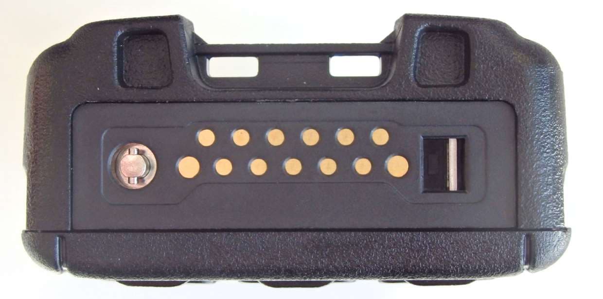
XX6SC2124
Apr 15, 2020TETRA Portable Handheld Terminal
Equipment Class
DSS - Part 15 Spread Spectrum Transmitter