XYD-2NXDTelecell with location and dimming control
Telensa Ltd.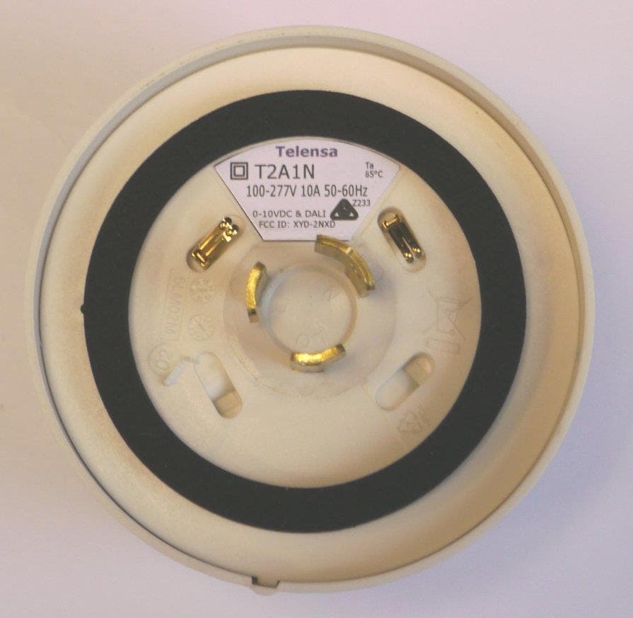
Click to zoom
Application Details
- Equipment Class
- DSS - Part 15 Spread Spectrum Transmitter
- Date of Grant
- Oct 29, 2014
- Application Purpose
- Original Equipment
- Date of Application
- Oct 29, 2014
- Equipment Note
- Telecell with location and dimming control
- Frequency Range
- 910.50000000 - 919.97500000
- Company
- Telensa Ltd.
- Country
- United Kingdom
Documents & Files
Document Text
Text extracted from the exhibit documents filed with the FCC. Open a document above to read the original.
Users Manual
COMMERCIAL IN CONFIDENCE 6LT041 05 29 Oct 2014 Page 1 of 9 QP4016 06 - Tech Note Template Technical Note Subject: User Manual and instructions for the EU & US Telecell Date: 29 Oct 2014 Document ref: 6LT041 05 Intentionally Blank 6LT041 05 29 Oct 2014 QP4016 07- Tech Note Template Telensa Telecell 2 User Manual 6LT041 05 29 Oct 2014 QP4016 07- Tech Note Template Contents CONTENTS ................................................................................................................................................................ 3 1 OPERATIONAL SAFETY NOTICES ............................................................................................................ 4 2 TELECELL VARIANTS .................................................................................................................................. 4 3 SPECIFICATIONS ........................................................................................................................................... 4 3.1 EU TYPE PRODUCTS, T2E... ....................................................................................................................... 4 3.2 US TYPE PRODUCTS, T2A... ....................................................................................................................... 4 3.3 NOTES ON DIMMING CONTROL OUTPUTS ...................................................................................................... 5 4 INSTALLATION INSTRUCTIONS ............................................................................................................... 5 4.1 DIMMING CONTROL TELECELL .................................................................................................................... 5 4.2 STANDARD (NON DIMMING) TELECELL ........................................................................................................ 5 5 TELECELL CONNECTION DIAGRAMS .................................................................................................... 6 6 NOTICES FOR PRODUCTS OPERATED IN THE USA & CANADA ...................................................... 9 6LT041 05 29 Oct 2014 QP4016 07- Tech Note Template 1 Operational Safety Notices Installer Installers must be suitably trained and qualified for electrical work, according to the laws and local codes for the locality and country where the unit will be installed. This unit must only be installed by personnel that have been trained by Telensa or their representatives to carry out this work. Power Supply In the case of field installation the supply voltage present on the luminaire NEMA socket is hazardous and all necessary precautions must be taken to ensure the safety of the installer. Isolate the supply to the NEMA socket before removing an old photocontrol, or installing the telecell. 2 Telecell Variants There are two variants of the Telecell 2 model; dimming control and standard / non-dimming control. Dimming control products are identified by the text “0-10V & DALI” on the product label. Telecell products are built and supplied to either the EU or US standards: EU product part numbers start with: T2E... US part numbers start with T2A... The products are supplied with NEMA pin connections for insertion into the photocell socket on top of a luminaire. 3 Specifications 3.1 EU Type Products, T2E... Electrical Parameters: Supply voltage: 100 - 253 VAC, 50-60Hz Maximum switching current: 10A Radio: Transmit Power: 25mW EIRP, <1% transmit duty cycle. Operating band: 868MHz license free ISM band Operating Temperature: NEMA variants: -40 to 70 °C Ambient 3.2 US Type Products, T2A... Electrical Parameters: Supply voltage: 100 - 277 VAC, 50-60Hz Maximum switching current: 10A Radio: Transmit Power: 100mW EIRP Operating band: 915MHz license free ISM band Operating Temperature: NEMA variants: -40 to 70 °C Ambient 6LT041 05 29 Oct 2014 QP4016 07- Tech Note Template 3.3 Notes on dimming control outputs These notes apply to products with the integrated dimming control function: Suitable for use with dimmable ballasts with an isolated or non-isolated control input DALI or 0-10V control mode is configured over the air by the Telensa Central System 0-10V control requires the normally fitted internal pull-up resistor in the ballast DALI control includes the DALI supply function within the telecell and is suitable for controlling from one to three dimmable ballasts. 4 Installation Instructions Instructions for the installation of each of the different variants of Telecell are given below. Figure 2 shows a wiring diagram for a standard lamp with a non-dimmable ballast. Figure 3 shows dimming control using a dimmable ballast. 4.1 Dimming Control Telecell This product will ONLY control a lamp that incorporates a 5 or 7 pin NEMA socket compliant with ANSI C136.41 2013. Insert unit into NEMA socket on street light ensuring the largest tab on the unit places into the largest tab recess on the NEMA socket on the street light. Turn by hand clockwise typically 30 degrees to lock in place. 4.2 Standard (non dimming) Telecell Insert unit into NEMA socket on street light ensuring the largest tab on the unit places into the largest tab recess on the NEMA socket on the street light. Turn by hand clockwise typically 30 degrees to lock in place. 6LT041 05 29 Oct 2014 QP4016 07- Tech Note Template Fig 1: Example NEMA socket showing alignment 5 Telecell Connection Diagrams Refer to figures 2 and 3 overleaf. Colour code Function Notes Brown LIVE/LINE in Blue NEUTRAL in Red LIVE switched out Relay switched inside telecell Violet + Dimmer control Integrated dimming function telecells only. DALI control is not polarity sensitive. Grey - Dimmer control 6LT041 05 29 Oct 2014 QP4016 07- Tech Note Template Figure 2: Wiring Diagram for Telecell - No Dimming Function 6LT041 05 29 Oct 2014 QP4016 07- Tech Note Template Telecell Dimmable Ballast Lamp Live in NeutralLive out Dimmer control Lamp Lamp Neutral Live in Ctrl 1 Ctrl 2 Figure 3: Wiring Diagra…
Text truncated - open the document above for the full version.
Attestation Statements
COMMERCIAL IN CONFIDENCE Your ref: FCC Application by Telensa Our ref: 6LC003 01 Date : 16 Oct 2014 To whom it may concern, Attestation concerning Plextek documentation and Telensa FCC applications This letter is to confirm that Plextek Consulting freely allows Telensa Ltd, (of Plextek building, London Rd, Gt Chesterford, CB10 1NY, UK), the right to use Plextek originated documents in their application for FCC certification of their products. Plextek is a consultancy that designs products for Telensa Limited. Yours sincerely, Mike Martindell Project Manager for Telensa designs Telecommunication Certification Body UL VS Ltd, Offices 18-26 Grove House, Lutyens Close, Chineham Court, Basingstoke RG24 8AG UK
Cover Letter(s)
Telensa Telensa Ltd. Plextek Building London Road Great Chesterford Essex CB10 1NY tel: 01799 533200 www.telensa.com COMMERCIAL IN CONFIDENCE Our ref: 6LC002 01 Date : 22 Sep 2014 To whom it may concern, FCC Agency letter This is to certify that Telensa authorises UL VS Ltd. to act on our behalf for the application of the telecell product, FCC ID: XYD-2NXD to UL VS Ltd. Telecommunication Certification Body. We certify that we are not subject to a denial of Federal benefits, that include FCC benefits, pursuant to Section 5301 of the Anti-Drug Abuse Act of 1988, 21 U.S.C. § 862 because of a conviction for possession or distribution of a controlled substance. See 47 CFR 1.2002(b) for the definition of a "party" for these purposes. Yours faithfully, Will Gibson DIRECTOR Telecommunication Certification Body UL VS Ltd, Offices 18-26 Grove House, Lutyens Close, Chineham Court, Basingstoke RG24 8AG UK
Cover Letter(s)
Telensa Telensa Ltd. Plextek Building London Road Great Chesterford Essex CB10 1NY tel: 01799 533200 www.telensa.com Registered in England no. 4498125 Registered Office: Plextek Building, London Road, Great Chesterford, Essex CB10 1NY 6 October 2014 Telecommunication Certification Body UL VS Ltd, Offices 18-26 Grove House, Lutyens Close, Chineham Court, Basingstoke Hampshire RG24 8AG United Kingdom Subject: Permanent Confidentiality Request Certification Application FCC ID: XYD-2NXD To whom it may concern, Pursuant to Sections 0.457 and 0.459 of CFR 47, Telensa Ltd request that the following information, provided to support the FCC application for the T2A1N-G-3 product, “Telecell with location and dimming”, FCC ID: XYD-2NXD be held permanently confidential: Block Diagram Operational Description Schematics The above material contains trade secrets not customarily released to public that are judged to have the potential to cause detriment to the applicant and provide unjustified benefits to its’ competitors. This information should not be available for public disclosure for an indefinite period of time. Yours faithfully Director
Cover Letter(s)
UL VS Ltd Pavilion A, Ashwood Park, Ashwood Way, Basingstoke, Hampshire, RG23 8BG T: +44 (0)1256 312000 / F: +44 (0)1256 312001 / E: [email protected] / W: www.ul.com Registered in England and Wales Company Number: 2117901 30 October 2014 TCB Address Change This is to confirm that the FCC listed address for UL VS Ltd TCB is in process of changing from: UL VS Ltd Pavilion A Ashwood Park Ashwood Way Basingstoke RG23 8BG United Kingdom To: UL VS Ltd, Offices 18-26 Grove House Lutyens Close Chineham Court Basingstoke RG24 8AG United Kingdom UL VS Ltd TCB
External Photos
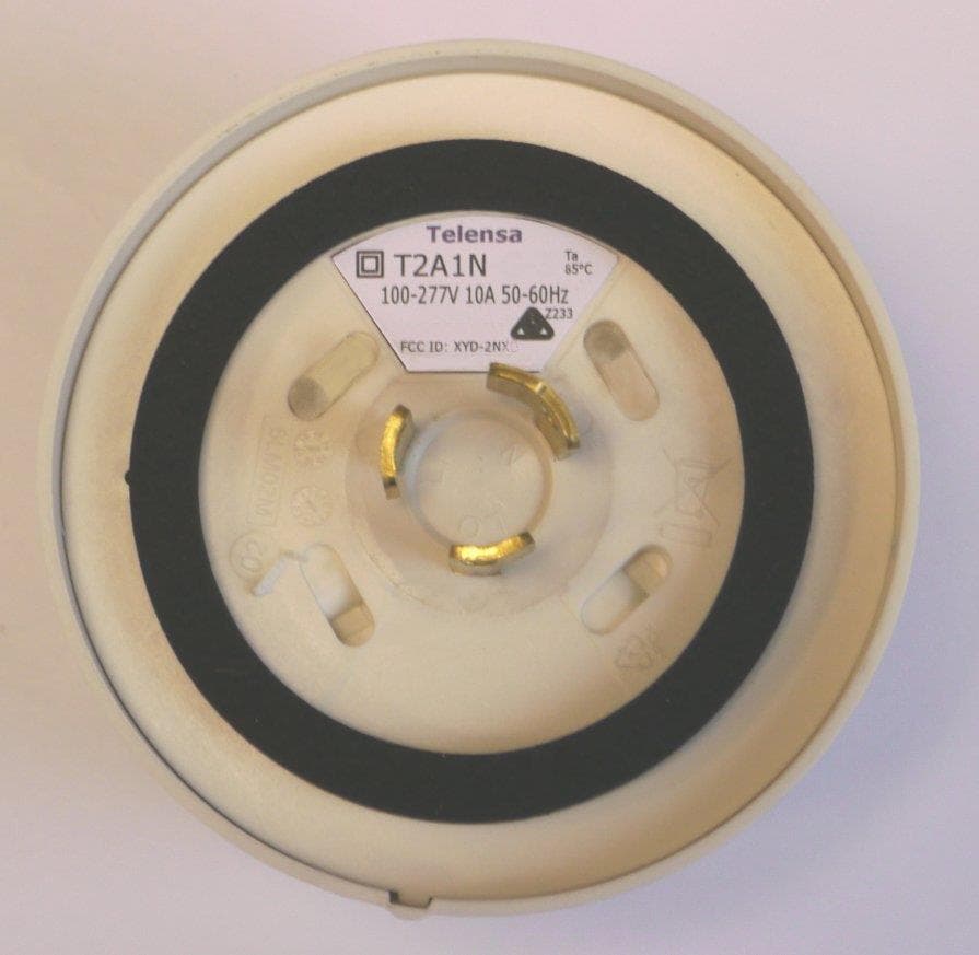
External Photographs for XYD-2NXD Top: Side: Base:
ID Label/Location Info
Telensa Plextek Ltd. Plextek Ltd. owns the copyright of this drawing which is not to be copied, reproduced or disclosed, in part or whole without prior written permission. Title Drg. No. Communications Technology Consultants Project Drawn Checked Approved London Road, Great Chesterford, Tel: +44 (0)1799 533200Fax: +44 (0)1799 533201 Essex CB10 1NY A4 Sht. of Scale Material Finish GENERAL TOLERANCES UNLESS STATED OTHERWISE : LINEAR ±0.1, HOLES Ø ±0.1 DO NOT SCALE - IF IN DOUBT ASK UNLESS OTHERWISE STATED ALL DIMENSIONS ARE IN : mm Initials Version DateECN /ECR NTS SJF Material: Reverse Printed LT175 Polyester Adhesive: 3m 467 Background Colour: White Text - Verdana Font, Colour Black unless otherwise stated WFC 01 03-Oct-14 1.7 mm high, bold C98 M96 Y12 K3 Telecell Label, T2A1N-G-3 LUMEN 6LM03L01 1 1 - XXX XXX 13,6 1 mm high,two lines 2.2 mm high 1.8 mm high 1 mm high, two lines 69° R27 Square: outer 2.5x2.5 Inner 1.5x1.5 T2A1N-G-3 100-277V 10A 50-60Hz FCC ID: XYD-2NXD 0-10VDC & DALI Ta 70°C Z233 1 mm high 3 mm high
ID Label/Location Info
FCC Label Location on base of unit:
Internal Photos
Internal Photographs for XYD-2NXD PCB bottom: Note that no screening cans are fitted to the product. PCB Top: Assembled internal view 1: Assembled internal view 2:
RF Exposure Info
6LT048 03 20 Oct 2014 Page 1 of 2 QP4016 07- Tech Note Template Technical Note Subject: FCC Submission - Telecell RF Radiation Exposure Levels Date: 20 Oct 2014 Document ref: 6LT048 03 1 Summary This document outlines RF radiation exposure level calculations for the Telecell products. Levels are specified as a power density. Limits are those defined in FCC § 1.1310 Radio frequency radiation exposure limits. In summary, the RF radiation exposure levels at a distance of 20 cm are below the specified FCC limits. 2 FCC § 1.1310 Limits 2.1 Limits for General Population/Uncontrolled Exposures Telecells are deployed by trained personnel and fixed to the top of streetlight luminaires. However, the devices are used within the vicinity of the public so the limit from table 1(B) applies: Limit: 1500 lim f PD mW/cm 2 , where f is the frequency in MHz. At the minimum frequency of 910.5 MHz, the limit is 0.61 mW/cm 2 . 3 RF Radiated Exposure Calculations 3.1 Power Density Expression The power density, PD, at a range R from the transmitter with an effective isotropic radiated power EIRP, is given by: 2 4R EIRP PD . To calculate the closest range at which the power density reaches the FCC limits, the following expression is used. lim 4PD EIRP R . 3.1.1 Power Density at 20 cm A worst case EIRP of 100 mW is assumed for the Telecell. This is made on the basis that the maximum conducted power is 100mW, and the specified antenna has a measured gain of 0dBi. At 20 cm, the power density is 0.02 mW/cm 2 , which is below the FCC limit of 0.61 mW/cm 2 . This is based on a duty cycle of 100%. However, during normal operation, the transmit duty cycle will typically be less than 1% when averaged over a 30 minute period which will mean that in practice the averaged power density will be closer to 0.0002mW/ cm 2 . 6LT048 03 20 Oct 2014 Page 2 of 2 QP4016 07- Tech Note Template 3.1.2 Minimum safe distance Assuming a worst case EIRP of 100mW and a duty cycle of 1%, the power density meets the FCC limit at a distance of 0.36 cm.
Test Report
UL VS LTD Pavilion A, Ashwood Park, Ashwood Way, Basingstoke, Hampshire, RG23 8BG, UK Telephone: +44 (0)1256 312000 Facsimile: +44 (0)1256 312001 TEST REPORT Test Report No. : UL-RPT-RP10445344JD01A V2.0 Manufacturer : Telensa Ltd Model No. : T2A1N-G-3 FCC ID : XYD-2NXD IC Certification No. : 12199A-2NXD Technology : FHSS Test Standard(s) : FCC Parts 15.107(a), 15.109, 15.207, 15.209(a) & 15.247 Industry Canada RSS-210 A8.1(b), A8.1(c), A8.4(1) & A8.5; RSS-Gen 4.6.3, 4.8, 4.9 & 7.2.4 1. This test report shall not be reproduced in full or partial, without the written approval of UL VS LTD. 2. The results in this report apply only to the sample(s) tested. 3. The sample tested is in compliance with the above standard(s). 4. The test results in this report are traceable to the national or international standards. 5. Version 2.0 supersedes all previous versions. Date of Issue: 27 October 2014 Checked by: Ian Watch Senior Engineer, Radio Laboratory Issued by : pp John Newell Quality Manager, UL VS LTD This laboratory is accredited by UKAS. The tests reported herein have been performed in accordance with its terms of accreditation. TEST REPORT SERIAL NO: UL-RPT-RP10445344JD01A V2.0 VERSION 2.0 ISSUE DATE: 27 OCTOBER 2014 Page 2 of 52 UL VS LTD This page has been left intentionally blank. TEST REPORT SERIAL NO: UL-RPT-RP10445344JD01A V2.0 VERSION 2.0 ISSUE DATE: 27 OCTOBER 2014 UL VS LTD Page 3 of 52 Table of Contents 1. Customer Information ................................................................................................................ 4 2. Summary of Testing ................................................................................................................... 5 2.1. General Information 5 2.2. Summary of Test Results 6 2.3. Methods and Procedures 6 2.4. Deviations from the Test Specification 6 3. Equipment Under Test (EUT) .................................................................................................... 7 3.1. Identification of Equipment Under Test (EUT) 7 3.2. Description of EUT 7 3.3. Modifications Incorporated in the EUT 7 3.4. Additional Information Related to Testing 8 3.5. Support Equipment 9 4. Operation and Monitoring of the EUT during Testing ............................................................10 4.1. Operating Modes 10 4.2. Configuration and Peripherals 10 5. Measurements, Examinations and Derived Results ...............................................................11 5.1. General Comments 11 5.2. Test Results 12 5.2.1. Receiver/Idle Mode AC Conducted Spurious Emissions 12 5.2.2. Receiver/Idle Mode Radiated Spurious Emissions 16 5.2.3. Transmitter AC Conducted Spurious Emissions 20 5.2.4. Transmitter 20 dB Bandwidth 23 5.2.5. Transmitter Carrier Frequency Separation 27 5.2.6. Transmitter Number of Hopping Frequencies and Average Time of Occupancy 29 5.2.7. Transmitter Maximum Peak Output Power 33 5.2.8. Transmitter Radiated Emissions 38 5.2.9. Transmitter Radiated Emissions 40 5.2.10. Transmitter Band Edge Radiated Emissions 47 6. Measurement Uncertainty ........................................................................................................51 7. Report Revision History ...........................................................................................................52 TEST REPORT SERIAL NO: UL-RPT-RP10445344JD01A V2.0 VERSION 2.0 ISSUE DATE: 27 OCTOBER 2014 Page 4 of 52 UL VS LTD 1. Customer Information Company Name: Telensa Ltd Address: Plextek Building London Road Great Chesterford Essex CB10 1NY United Kingdom TEST REPORT SERIAL NO: UL-RPT-RP10445344JD01A V2.0 VERSION 2.0 ISSUE DATE: 27 OCTOBER 2014 UL VS LTD Page 5 of 52 2. Summary of Testing 2.1. General Information Specification Reference: 47CFR15.247 Specification Title: Code of Federal Regulations Volume 47 (Telecommunications): Part 15 Subpart C (Intentional Radiators) - Section 15.247 Specification Reference: 47CFR15.107 and 47CFR15.109 Specification Title: Code of Federal Regulations Volume 47 (Telecommunications): Part 15 Subpart B (Unintentional Radiators) - Sections 15.107 and 15.109 Specification Reference: 47CFR15.207 and 47CFR15.209 Specification Title: Code of Federal Regulations Volume 47 (Telecommunications): Part 15 Subpart C (Intentional Radiators) - Sections 15.207 and 15.209 Specification Reference: RSS-Gen Issue 3 December 2010 Specification Title: General Requirements and Information for the Certification of Radio Apparatus Specification Reference: RSS-210 Issue 8 December 2010 Specification Title: Licence-exempt Radio Apparatus (All Frequency Bands): Category I Equipment. Site Registration: FCC: 209735; Industry Canada: 3245B-2 Location of Testing: UL VS LTD, Unit 3 Horizon, Wade Road, Kingsland Business Park, Basingstoke, Hampshire, RG24 8AH, United Kingdom Test Dates: 11 September 2014 to 21 October 2014 TEST REPORT SERIAL NO: UL-RPT-RP10445344JD01A V2.0 VERSION 2.0 ISSUE DATE: 27 OCTOBER 2014 Page 6 of 52 UL VS LTD 2.2. Summary of Test Results FCC Reference (47CFR) IC Reference Measurement Result Part 15.107(a) RSS-Gen 7.2.4 Receiver/Idle Mode AC Conducted Emissions Part 15.109 N/A Receiver/Idle Mode Radiated Spurious Emissions Part 15.207 RSS-Gen 7.2.4 Transmitter AC Conducted Emissions Part 15.247(a)(1)(i) RSS-Gen 4.6.3 RSS-210 A8.1(c) Transmitter 20 dB Bandwidth Part 15.247(a)(1) RSS-210 A8.1(b) Transmitter Carrier Frequency Separation Part 15.247(a)(1)(i) RSS-210 A8.1(c) Transmitter Number of Hopping Frequencies and Average Time of Occupancy Part 15.247(b)(2) RSS-Gen 4.8 RSS-210 A8.4(1) Transmitter Maximum Peak Output Power Part 15.247(d)/ 15.209(a) RSS-Gen 4.9 RSS-210 A8.5 Transmitter Radiated Emissions Part 15.247(d)/ 15.209(a) RSS-Gen 4.9 RSS-210 A8.5 Transmitter Band Edge Radiated Emissions Key to Results = Complied = Did not comply 2.3. Methods and Procedures Reference: ANSI C63.4 (2009) Title: American National Standard for Methods of Measurement of Radio-Noise Emissions from Low-Voltage Electrical and Electronic…
Text truncated - open the document above for the full version.
Test Setup Photos
Plextek Ltd FCC ID: XYD-2NXD UL-RPT-10445344JD01 IC: 12199A-2NXD UL VS LTD 1 Test Setup Photographs for the Telensa T2A1N-G-3 1. Radiated Emissions 1.1 Configuration 1: Rx RSE Photo 1 Photo 2 Plextek Ltd FCC ID: XYD-2NXD UL-RPT-10445344JD01 IC: 12199A-2NXD 1.2 Radiated Emissions Configuration 2: Tx RSE Photo 1 Photo 2 Plextek Ltd FCC ID: XYD-2NXD UL-RPT-10445344JD01 IC: 12199A-2NXD UL VS LTD 3 1. AC Conducted Emissions 2.1 Configuration 1: - Photo 1 Plextek Ltd FCC ID: XYD-2NXD UL-RPT-10445344JD01 IC: 12199A-2NXD Photo 2
Contact Information
Applicant
Michael Coelho(Mr.)
Technical Contact
Telensa Ltd.Mike Brown
[email protected]+44 1799 533200
Plextek Building · Great Chesterford · United Kingdom
Non-Technical Contact
Telensa Ltd.Will Gibson
[email protected]+44 1799 533200
Test Firm
UL VS LtdDarren Rust
Technical Specifications
| # | Rule Parts | Frequency Range | Power Output |
|---|---|---|---|
| 1 | 15C | 910.5 MHz - 919.975 MHz | 87.00 mW |
Other Applications from Telensa Ltd.
XYD-2NXN
Oct 29, 2014Telecell with location
Equipment Class
DSS - Part 15 Spread Spectrum Transmitter
XYD-TBSA1
Jun 17, 2012Part 15 Spread Spectrum Transmitter
Equipment Class
DSS - Part 15 Spread Spectrum Transmitter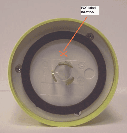
XYD-TCNM-V
May 20, 2010Streetlight Control and Monitoring Device
Equipment Class
DSS - Part 15 Spread Spectrum Transmitter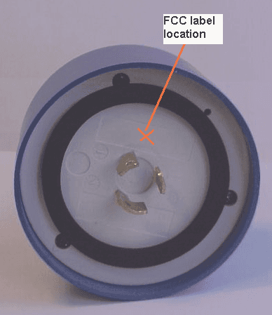
XYD-TCNM-E
May 20, 2010Streetlight Control and Monitoring Device
Equipment Class
DSS - Part 15 Spread Spectrum Transmitter