Y22-SK20120002PLYR 2
Skullcandy Inc.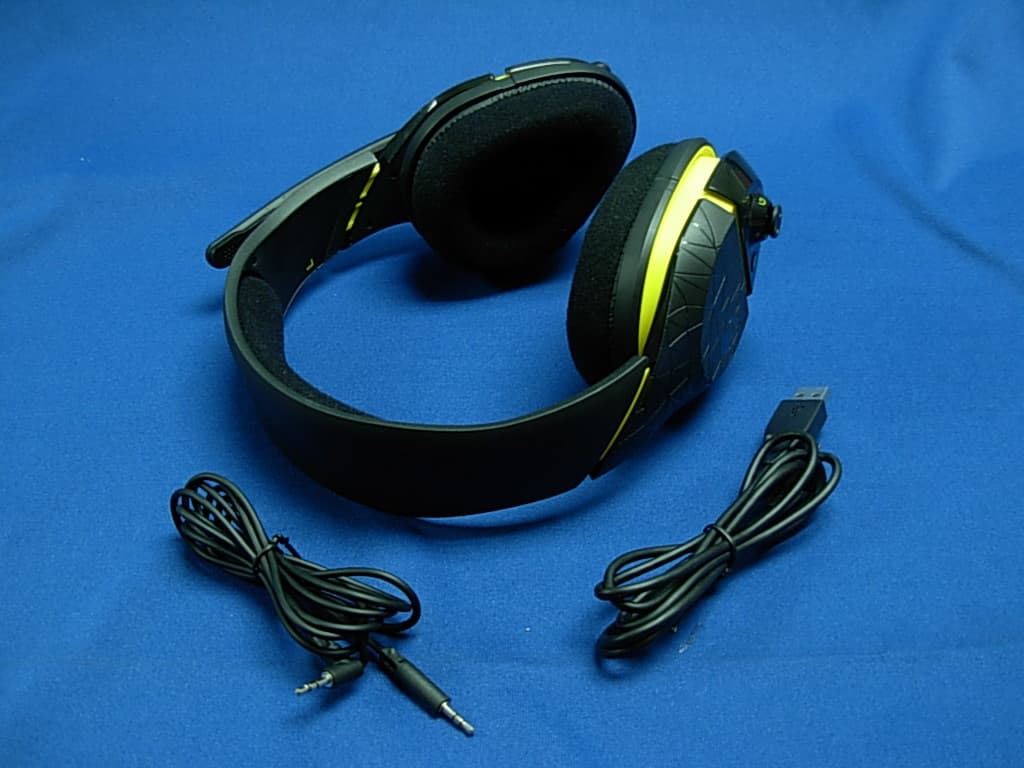
Click to zoom
Application Details
- Equipment Class
- DTS - Digital Transmission System
- Date of Grant
- Jan 06, 2013
- Application Purpose
- Original Equipment
- Date of Application
- Jan 03, 2013
- Equipment Note
- PLYR 2
- Frequency Range
- 2403.35000000 - 2477.35000000
- Company
- Skullcandy Inc.
- Country
- United States
Documents & Files
Document Text
Text extracted from the exhibit documents filed with the FCC. Open a document above to read the original.
Users Manual
Skullcandy PLYR 2 User Manual Contents 04 Introduction 05 About THE PLYR 2 06 ABOUT DOLBY SURROUND TECHNOLOGY 07 CONTROLS 09 PACKAGE CONTENTS 11 SETUP 16 CONSOLE SETUP - TV 18 CONSOLE SETUP - HOME THEATER 20 PC SETUP 22 PC SETUP LAN 24 TROUBLESHOOTING 27 WARRANTY 29 FCC Statement Contents P2 Introduction ABOUT THE PLYR 2 Congratulations on your purchase of the SKULLCANDY Gaming PLYR 2! Whether you’re a casual player or a pro gamer, we’d like to welcome you into the SKULLCANDY family of gaming accessories. The PLYR 2 is the result of countless hours of research and development by the foremost experts in the audio industry, extremely talented industrial designers, and SKULLCANDY’s own internal team of gamers. Plus, it’s tweaked with SKULLCANDY Supreme Sound, so you know your games and other media are going to sound their best. The PLYR 2 contains a complex electronics package, so check out the rest of this instruction booklet if you have a minute. If you’re too smart for manuals, save it anyway for later reference: it contains important warranty information and a handy troubleshooting guide. The PLYR 2 is a wireless headset system. Whether you’re gaming or watching movies at home alone or with your friends, on a console or a PC, the PLYR 2 has something to offer. For Xbox 360 and PlayStation 3 users, the PLYR 2 wirelessly combines voice communication and game surround sound. Connect the wireless transmitter to your console, and you’re good to go. For Home Theater setups, it’s easy to get crystal-clear wireless sound for your favorite movies and TV shows. Simply run the 3.5mm to RCA connection from your TV, media playback device or stereo receiver to the GMX Stereo Transmitter wireless transmitter, sit back and enjoy. You can adjust master volume and the EQ’s from the headset and keep your neighbors off your back. For PC and Mac gamers whose sound card has a 3.5mm jack, the GMX Stereo Transmitter can be used to listen to your favorite games, music, videos and movies. Same deal as above, connect via 3.5mm cable or USB cable and you’re good to go. Voice communication is supported by running our USB Chat Cable (sold separately) into the USB connection on your computer. The PLYR 2 enables your computer to offload surround sound decoding and will combine multiple audio streams thanks to its built-in USB audio input. By setting your VoIP program to use the PLYR 2 (called SKULLCANDY GMX Stereo Transmitter in your audio profiles) as the USB input/output device, full hardware mixing is enabled between voice communication, game sound, and music. P4 introduction ABOUT THE PLYR 2 P5 CONTROLS With the SKULLCANDY Gaming PLYR 2, it’s easy to control your gaming or home theater audio experience. The MASTER VOLUME control on the headset raises and lowers volume of all incoming audio feeds together. It will not raise or lower the volume of your outgoing voice communication. (The distance between your microphone and your mouth is the best way to adjust this). The BALANCE control on the headset enables you to dial in the perfect mix of game-to- voice communication. Important: It is possible to bring either the GAME or the VOICE volume down to 0% volume, at either end of the BALANCE control dial spectrum. The EQ3 switch on the Headset switches between the three EQ modes: Bass Mode (best for movies and games with a lot of action), Supreme Mode (neutral tuning for no enhancements and good for music), and Precision Mode (for accurate sound in FPS games). Mic mute can be achieved by flipping the mic to the up position, and unmuted by bringing it to the down position. The MASTER POWER buttons on the Headset and GMX Stereo Transmitter do exactly what you might expect, but also are used for pairing by first holding down the GMX Stereo Transmitter button until it blinks white, and then doing the same with the Headset Important: When the headset is idle (no signal detected for 5 minutes), the Headset will automatically shut down. This feature is to prevent draining the battery when no headset is connected. If you reconnect your headset within a short period of time, the unit will automatically return to the state you had it in before it was disconnected. If you reconnect after this short time, you’ll need to restart it manuall CONTROLs P6 When your Headset’s batteries are low, the amber power indicator will flash ON and OFF intermittently. There is also an audio beep/alarm for when your batteries are low, giving you approximately 15% of power left depending on the battery’s chemistry. A SOLID AMBER button indicates adequate power. PACKAGE CONTENTS PLYR 2 Headset Headset with mic, controls, wireless receiver, and embedded rechargeable battery. GMX Stereo Transmitter Wireless Transmitter and all connections GMX Stereo Transmitter USB Power Cable The PLYR 2 GMX Stereo Transmitter needs juice, so plug one end into the USB port on your console and the other into the input marked PWR on the rear of the GMX Stereo Transmitter. 3.5mm to RCA Cable The PLYR 2 GMX Stereo Transmitter also needs an audio input, so run this from your gaming console, TV, home theater receiver or computer to the input marked input on the back. 2.5mm-to-2.5mm Xbox Live Controller cable This cable handles the Xbox Live communication between your controller and the PLYR 2 Headset. Just connect it from the bottom of the controller to the 2.5mm input on the bottom of the Headset with a small icon of a game controller. USB-to-USB Mini ‘B’ cable This cable powers the PLYR 2 Headset when you want to conserve battery power or need to recharge your rechargeable battery kit (available separately). Connect it to any USB port on your PC or gaming console and the other end to the PLYR 2 headset. P7 CONTROLS SETUP The Package Contents list should have already given you a good idea of how each cable included with the PLYR 2 fits into your system before you get started. You probably already have your PLYR 2 up and running, but just in case here are a few scenarios you …
Text truncated - open the document above for the full version.
External Photos
Report No: 129270R-RFUSP42V01-A Page: 59 of 65 Attachement EUT Photograph (1) EUT Photo (2) EUT Photo Report No: 129270R-RFUSP42V01-A Page: 60 of 65 (3) EUT Photo (4) EUT Photo Report No: 129270R-RFUSP42V01-A Page: 61 of 65 (5) EUT Photo (6) EUT Photo
ID Label/Location Info
Skullcandy 1441 W. Ute Blvd Suite 250, Park City, UT 84098, U.S.A. FCC ID.: Y22-SK20120002 FCC ID AND DoC Label
ID Label/Location Info
Skullcandy 1441 W. Ute Blvd Suite 250, Park City, UT 84098, U.S.A. FCC ID.: Y22-SK20120002 FCC ID AND DoC Label
Internal Photos
Report No: 129270R-RFUSP42V01-A Page: 62 of 65 (7) EUT Photo (8) EUT Photo Report No: 129270R-RFUSP42V01-A Page: 63 of 65 (9) EUT Photo (10) EUT Photo Report No: 129270R-RFUSP42V01-A Page: 64 of 65 (11) EUT Photo (12) EUT Photo Report No: 129270R-RFUSP42V01-A Page: 65 of 65 (13) EUT Photo (MB) (14) EUT Photo (ANT)
Test Report
Report No: 129270R-RFUSP42V01-A Page: 1 of 65 Test Report Product Name : PLYR 2 Model No. : SMPLFY-207, SMPLFY-205, SMPLFY-280 FCC ID. : Y22-SK20120002 Applicant : Skullcandy Address : 1441 W. Ute Blvd Suite 250, Park City, UT 84098, U.S.A. Date of Receipt:2012/09/12 Issued Date :2012/10/02 Report No. :129270R-RFUSP42V01-A Report Version :V1.0 The test results relate only to the samples tested. The test report shall not be reproduced except in full without the written approval of QuieTek Corporation. Report No: 129270R-RFUSP42V01-A Page: 2 of 65 Test Report Certification Issued Date : 2012/10/02 Report No. : 129270R-RFUSP42V01-A Product Name : PLYR 2 Applicant : Skullcandy Address : 1441 W. Ute Blvd Suite 250, Park City, UT 84098, U.S.A. Manufacturer : Merry Electronics (Shenzhen) Co., Ltd. Model No. : SMPLFY-207, SMPLFY-205, SMPLFY-280 FCC ID. : Y22-SK20120002 EUT Voltage : DC 3.7V (Power by Battery) DC 5V (Power by PC) Trade Name : SKULLCANDY Applicable Standard : FCC CFR Title 47 Part 15 Subpart C Section 15.247: 2011 Test Result : Complied The test results relate only to the samples tested. The test report shall not be reproduced except in full without the written approval of QuieTek Corporation. Documented By : ( Demi Chang / Engineering Adm. Specialist ) Reviewed By : ( Ben Huang / Engineer ) Approved By : ( Roy Wang / Manager ) Report No: 129270R-RFUSP42V01-A Page: 3 of 65 Laboratory Information We, QuieTek Corporation, are an independent RF consultancy that was established the whole facility in our laboratories. The test facility has been accredited/accepted (audited or listed) by the following related bodies in compliance with ISO 17025 specified testing scopes: The related certificate for our laboratories about the test site and management system can be downloaded from QuieTek Corporation’s Web Site:http://www.quietek.com/tw/ctg/cts/accreditations.htm The address and introduction of QuieTek Corporation’s laboratories can be founded in our Web site : http://www.quietek.com/ If you have any comments, Please don’t hesitate to contact us. Our contact information is as below: HsinChu Testing Laboratory: No.75-2, 3rd Lin, Wangye Keng, Yonghxing Tsuen, Qionglin Shiang, Hsinchu County 307, Taiwan, R.O.C. TEL:+886-3-592-8858 / FAX:+886-3-592-8859 E-Mail : [email protected] LinKou Testing Laboratory: No.5-22, Ruishukeng, Linkou Dist., New Taipei City 24451, Taiwan, R.O.C. TEL : 886-2-8601-3788 / FAX : 886-2-8601-3789 E-Mail : service @quietek.com Suzhou Testing Laboratory: No. 99 Hongye Rd., Suzhou Industrial Park Loufeng Hi-Tech Development Zone., Suzhou,China. TEL : +86-512-6251-5088 / FAX : +86-512-6251-5098 E-Mail : [email protected] Taiwan R.O.C. : TAF, Accreditation Number: 1313 Germany : TUV Rheinland, Certificate No.: 10011438-2-2010 USA : FCC, Registration Number: 365520 Canada : IC, Submission No: 150981 Report No: 129270R-RFUSP42V01-A Page: 4 of 65 TABLE OF CONTENTS Description Page 1. General Information.............................................................................................................. 6 1.1. EUT Description ............................................................................................................. 6 1.2. Operational Description .................................................................................................. 8 1.3. Test Mode .......................................................................................................................9 1.4. Tested System Details .................................................................................................. 10 1.5. Configuration of tested System .................................................................................... 11 1.6. EUT Exercise Software ................................................................................................ 11 1.7. Test Facility...................................................................................................................12 2. Conducted Emission .......................................................................................................... 13 2.1. Test Equipment............................................................................................................. 13 2.2. Test Setup .................................................................................................................... 13 2.3. Limits ............................................................................................................................ 14 2.4. Test Procedure ............................................................................................................. 14 2.5. Test Specification.......................................................................................................... 14 2.6. Uncertainty ................................................................................................................... 14 2.7. Test Result....................................................................................................................15 2.8. Test Photo .................................................................................................................... 17 3. Peak Power Output ............................................................................................................ 18 3.1. Test Equipment............................................................................................................. 18 3.2. Test Setup .................................................................................................................... 18 3.3. Test procedures ............................................................................................................ 18 3.4. Limits ............................................................................................................................ 18 3.5. Test Specification.........................................................................................…
Text truncated - open the document above for the full version.
Test Setup Photos
Report No: 129270R-RFUSP42V01-A Page: 17 of 65 2.8. Test Photo Test Mode : Mode 1: Transmit-Headset Description: Front View of Conducted Emission Test Setup Test Mode : Mode 1: Transmit-Headset Description: Back View of Conducted Emission Test Setup Report No: 129270R-RFUSP42V01-A Page: 32 of 65 4.8. Test Photo Test Mode : Mode 1: Transmit-Headset Description: Front View of Radiated Emission Test Setup (Bilog) Test Mode : Mode 1: Transmit-Headset Description: Back View of Radiated Emission Test Setup (Bilog) Report No: 129270R-RFUSP42V01-A Page: 33 of 65 Test Mode : Mode 1: Transmit-Headset Description: Front View of Radiated Emission Test Setup (Horn) Test Mode : Mode 1: Transmit-Headset Description: Back View of Radiated Emission Test Setup (Horn)
Contact Information
Applicant
James Nance
Technical Contact
Test Firm
QuieTek CorporationWarren Lin
Technical Specifications
| # | Rule Parts | Frequency Range | Power Output |
|---|---|---|---|
| 1 | 15C | 2.40 GHz - 2.48 GHz | 3.00 mW |
Other Applications from Skullcandy Inc.
Y22-S8SSS
Aug 14, 2026Session 720
Equipment Class
DSS - Part 15 Spread Spectrum TransmitterY22-S6CNW
May 22, 2026Crusher 1080 ANC
Equipment Class
DTS - Digital Transmission SystemY22-S8SNS
May 22, 2026Session 900
Equipment Class
DSS - Part 15 Spread Spectrum TransmitterY22-S8SFS
Mar 23, 2026Session 540
Equipment Class
DTS - Digital Transmission SystemY22-S8STS
Mar 20, 2026Session 360
Equipment Class
DSS - Part 15 Spread Spectrum Transmitter