Y22-SK20130010Ringer
Skullcandy Inc.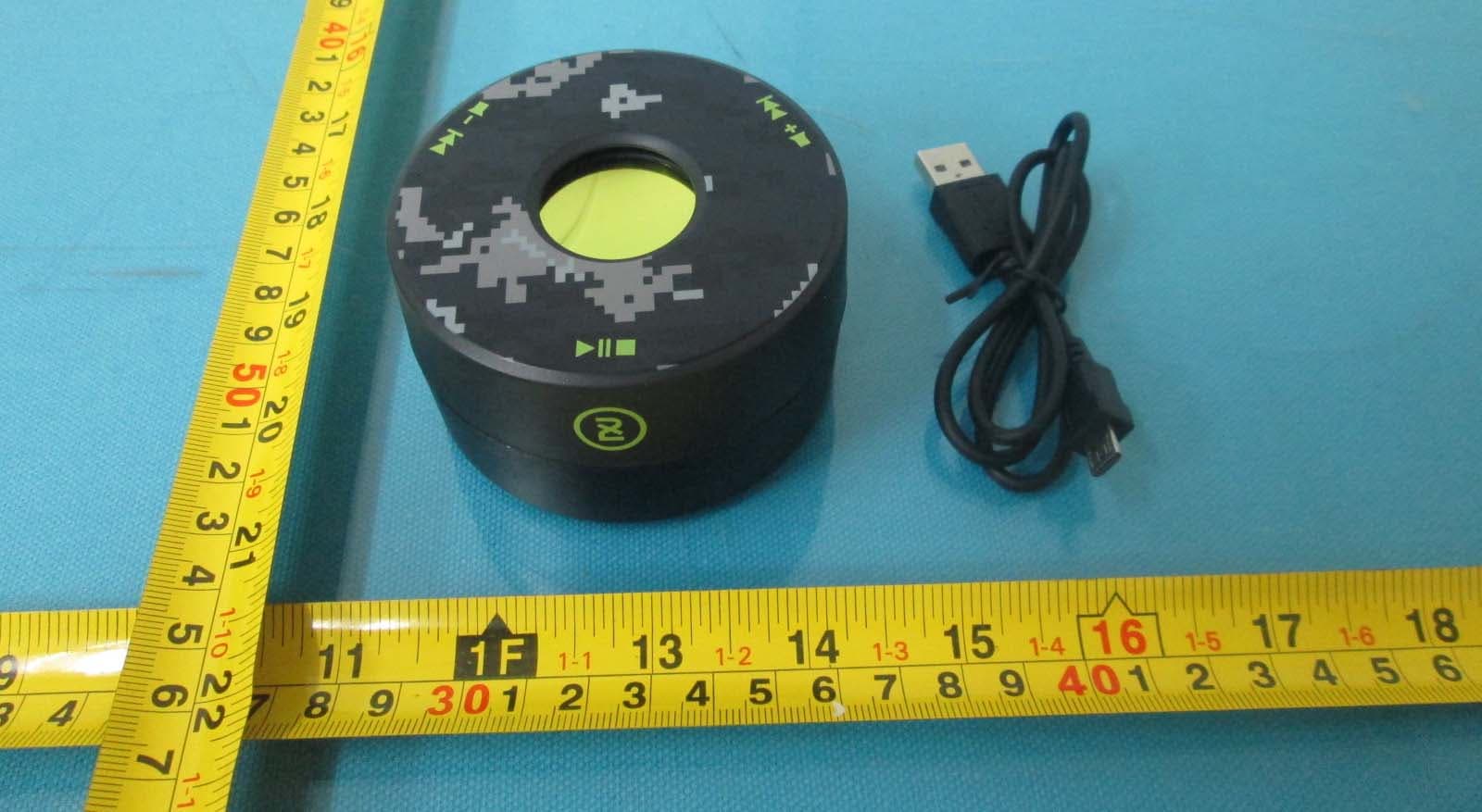
Click to zoom
Application Details
- Equipment Class
- DSS - Part 15 Spread Spectrum Transmitter
- Date of Grant
- Jul 10, 2014
- Application Purpose
- Original Equipment
- Date of Application
- Jul 10, 2014
- Equipment Note
- Ringer
- Frequency Range
- 2402.00000000 - 2480.00000000
- Company
- Skullcandy Inc.
- Country
- United States
Documents & Files
Document Text
Text extracted from the exhibit documents filed with the FCC. Open a document above to read the original.
Users Manual
User Guide // Manuel Utilisateur Power on/off // Bouton d’alimentation Press the power (play, pause, stop) button for 3 seconds or untill you hear a beep sound. A blue LED is indicate for power on, and a red LED is indicated for power off. Appuyez sur le bouton (play/pause/stop) pendant 3 secondes ou jusqu'à ce que vous entendiez un bip sonore un voyant bleu indique la mise sous tension, et un voyant rouge indique la mise hors tension. Pairing // Connexion/Jumelage When power is off. Press the power and hold until you hear two separate beeps. The LED indicator will blink blue and red. Pause // Pause Press the power button once to pause and once to play again. Appuyez sur le bouton marche/arrêt une fois pour mettre en pause et une fois de plus pour continuer. Volume up // Volume Haut Press the volume up/next track button once and let go. Permet d’augmenter le volume. Lorsque l’alimentation est coupée. Appuyez sur le bouton marche/arrêt et maintenez le jusqu’a que vous entendiez 2 bips distincts. Le voyant clignotera en bleue et rouge. Note: Button function is on bottom of Speaker. When placed on hard surface buttons can be used on top of speaker. NB: Les boutons de fonction sont au-dessous des haut-parleurs. Si l’appareil est placé sur une surface dure, les boutons peuvent-être utilisés sur le dessus. Volume down // Volume Bas Press the volume down/previous track button once and let go. Next track // Piste Suivante Press and hold the volume up/next track button for 3 seconds. Appuyez sur le volume haut et maintenez- le enfonce pendant 3 secondes, pour passer à la chanson suivante. Permet de diminuer le volume. Previous track // Piste Précédente Press and hold the volume down/previous track button for 3 seconds. Appuyez le volume bas et maintenez-le enfonce pendant 3 secondes, pour revenir à la chanson précédente. Charging // Chargement Simply plug in the micro USB into the charging port. The indicator turns red when charging, it's turn blue if fully charged. (Note: Music cannot be played while charging.) Simplement, branche un câble micro-USB dans le port de chargement. Le voyant deviendra rouge pendant le chargement, et deviendra bleue quand il est totalement charge, (NB: Aucune musique ne peut être jouée pendant le chargement). Note: This equipment has been tested and found to comply with the limits for a Class B digital device, pursuant to Part 15 of the FCC Rules. These limits are designed to provide reasonable protection against harmful interference in a residential installation. This equipment generates, uses, and can radiate radio frequency energy, and if not installed and used in accordance with the instructions, may cause harmful interference to radio communications. However, there is no guarantee that interference will not occur in a particular installation. If this equipment does cause harmful interference to radio or television reception, which can be determined by turning the equipment off and on, the user is encouraged to try to correct the interference by one or more of the following measures: – Reorient or relocate the receiving antenna. – Increase the separation between the equipment and receiver. – Connect the equipment into an outlet on a circuit different from that to which the receiver is connected. – Consult the dealer or an experienced radio/TV technician for help. You are cautioned that changes or modifications not expressly approved by the party responsible for compliance could void your authority to operate the equipment. This device complies with Part 15 of the FCC Rules. Operation is subject to the following two conditions: (1) this device may not cause harmful interference, and (2) this device must accept any interference received, including interference that may cause undesired operation. This device complies with Industry Canada licence-exempt RSS standard(s). Operation is subject to the following two conditions: (1) this device may not cause interference, and (2) this device must accept any interference, including interference that may cause undesired operation of the device. Le présent appareil est conforme aux CNR d'Industrie Canada applicables aux appareils radio exempts de licence. L'exploitation est autorisée aux deux conditions suivantes : (1) l'appareil ne doit pas produire de brouillage, et (2) l'utilisateur de l'appareil doit accepter tout brouillage radioélectrique subi, même si le brouillage est susceptible d'en compromettre le fonctionnement. FCC ID: Y22-2XL20130001 IC: 10486A-2XL20130001
Cover Letter(s)
DATE : Jun. 18, 2014 Equipment Autorisation Division Federal Communications Commission 7435 Oakland Mills Road Columbia, MD 21046 FCC ID: Y22-SK20130010 Product Name: Ringer Request for Confidentiality Pursuant to Sections 0.457 and 0.459 of the commissions rules, we hereby request that the following documents be held confidential: (List here the documents for which you are seeking confidentiality – for example ...) • Schematics • Block diagram • Operation description These materials contain trade secrets and proprietary information and are not customarily released to the public. The public disclosure of this information might be harmful to the company and provide unjustified benefits to our competitors. Dated this Agency agreement expiration date: Jun. 18, 2014 to Jun. 17, 2015 By: Thomas Bishop Signature Printed Title: Vice President of Product and Manufacturing On behalf of : Skullcandy Telephone: (435) 940-1545
Cover Letter(s)
Model difference The models are X7RGGZ-847, S7BUGW-445, S7BUGW-423, S7BUGW-446 and S7BUGW-447 , and all models are same product just different surface color and model names. Signature: Name / title: Thomas Bishop / Vice President of Product and Manufacturing Contact information / address: 1441 W. Ute Blvd Suite 250 Park City, UT 84098 United States
ID Label/Location Info
Label information: Label location
RF Exposure Info
The 1-g and 10-g SAR test exclusion thresholds for 100 MHz to 6 GHz at test separation distances ≤ 50 mm are determined by: [(max. power of channel, including tune-up tolerance, mW)/(min. test separation distance, mm)] · [√f(GHz)] ≤ 3.0 for 1-g SAR and ≤ 7.5 for 10-g extremity SAR, where z f(GHz) is the RF channel transmit frequency in GHz z Power and distance are rounded to the nearest mW and mm before calculation z The result is rounded to one decimal place for comparison The test exclusions are applicable only when the minimum test separation distance is ≤ 50 mm and for transmission frequencies between 100 MHz and 6 GHz. When the minimum test separation distance is < 5 mm, a distance of 5 mm is applied to determine SAR test exclusion. 3. EUT RF Exposure The Max Conducted Peak Output Power is 1.23dBm (1.33mW) in middle channel and the Max Conducted Average Output Power is less than 0.79mW. The best case gain of the antenna is 0dBi. 1.33/5*√2.441=0.42 ≤3.0 Conclusion: No SAR is required.
Test Report
Report No. : EESZG04210010 Page 1 of 61 TEST REPORT Product : Ringer Trade mark : Skullcandy Model/Type reference : X7RGGZ-847, S7BUGW-445, S7BUGW-423, S7BUGW-446, S7BUGW-447 Serial number : N/A Ratings : Charging input: 5V , 500mA lithium Battery: 3,7V 450mAh, IPX0, Class III FCC ID : Y22-SK20130010 Report number : EESZG04210010 Date : Jun. 04, 2014 Regulations : See below Test Standards Results 47 CFR FCC Part 15 Subpart C 15.247: 2013 PASS Prepared for: Skullcandy 1441 W. Ute Blvd Suite 250 Park City, UT 84098 United States Prepared by: Centre Testing International (Shenzhen) Corporation Hongwei Industrial Zone, 70 Area, Bao’an District, Shenzhen, Guangdong, China TEL: +86-755-3368 3668 FAX: +86-755-3368 3385 Tested by: Reviewed by: Approved by: Date: Jun. 04, 2014 Jimmy Li Lab manager Check No.: 1702004057 Report No. : EESZG04210010 Page 2 of 61 TABLE OF CONTENTS 1. GENERAL INFORMATION ............................................................................................ 4 2. TEST SUMMARY ........................................................................................................... 4 3. PRODUCT INFORMATION ............................................................................................ 5 4. MEASUREMENT UNCERTAINTY ................................................................................. 5 5. TEST EQUIPMENT LIST ............................................................................................... 5 6. SUPPORT EQUIPMENT LIST ....................................................................................... 5 7. 20DB / 99% BANDWIDTH MEASUREMENT ................................................................ 6 7.1. LIMITS ..................................................................................................................... 6 7.2. BLOCK DIAGRAM OF TEST SETUP ..................................................................... 6 7.3. TEST PROCEDURE ............................................................................................... 6 7.4. TEST RESULT ........................................................................................................ 6 8. CARRIER FREQUENCY SEPARATION ..................................................................... 16 8.1. LIMITS ................................................................................................................... 16 8.2. BLOCK DIAGRAM OF TEST SETUP ................................................................... 16 8.3. TEST PROCEDURE ............................................................................................. 16 8.4. TEST RESULT ...................................................................................................... 16 9. NUMBER OF HOPPING FREQUENCY ....................................................................... 22 9.1. LIMITS ................................................................................................................... 22 9.2. BLOCK DIAGRAM OF TEST SETUP ................................................................... 22 9.3. TEST PROCEDURE ............................................................................................. 22 9.4. TEST RESULT ...................................................................................................... 22 10. TIME OF OCCUPANCY (DWELL TIME) .................................................................. 26 10.1. LIMITS ................................................................................................................... 26 10.2. BLOCK DIAGRAM OF TEST SETUP ................................................................... 26 10.3. TEST PROCEDURE ............................................................................................. 26 10.4. TEST RESULT ...................................................................................................... 26 11. MAXIMUM PEAK CONDUCTED OUTPUT POWER MEASUREMENT ................... 32 11.1. LIMITS ................................................................................................................... 32 11.2. BLOCK DIAGRAM OF TEST SETUP ................................................................... 32 11.3. TEST PROCEDURE ............................................................................................. 32 11.4. TEST RESULT ...................................................................................................... 32 Report No. : EESZG04210010 Page 3 of 61 12. CONDUCTED BANDEDGE EMISSION MEASUREMENT ...................................... 35 12.1. LIMITS ................................................................................................................... 35 12.2. BLOCK DIAGRAM OF TEST SETUP ................................................................... 35 12.3. TEST PROCEDURE ............................................................................................. 35 12.4. TEST RESULT ...................................................................................................... 35 13. CONDUCTED SPURIOUS EMISSION MEASUREMENT ........................................ 42 13.1. LIMITS ................................................................................................................... 42 13.2. BLOCK DIAGRAM OF TEST SETUP ................................................................... 42 13.3. TEST PROCEDURE ............................................................................................. 42 13.4. TEST RESULT ...................................................................................................... 42 14. RADIATED BANDEDGE EMISSION / RADIATED SPURIOUS EMISSION MEASUREMENT ................................................................................................................. 45 14.1. LIMITS ................................................................................................................... 45 14.2. BLOCK DIAGRAM OF TEST SETUP ..…
Text truncated - open the document above for the full version.
Contact Information
Applicant
James Nance
Test Firm
Centre Testing InternationalLouisa Lu
[email protected]86-755-33683919
Technical Specifications
| # | Rule Parts | Frequency Range | Power Output |
|---|---|---|---|
| 1 | 15C | 2.40 GHz - 2.48 GHz | 1.33 mW |
Other Applications from Skullcandy Inc.
Y22-S8SSS
Aug 14, 2026Session 720
Equipment Class
DSS - Part 15 Spread Spectrum TransmitterY22-S6CNW
May 22, 2026Crusher 1080 ANC
Equipment Class
DTS - Digital Transmission SystemY22-S8SNS
May 22, 2026Session 900
Equipment Class
DSS - Part 15 Spread Spectrum TransmitterY22-S8SFS
Mar 23, 2026Session 540
Equipment Class
DTS - Digital Transmission SystemY22-S8STS
Mar 20, 2026Session 360
Equipment Class
DSS - Part 15 Spread Spectrum Transmitter