Y4O-DX18Wireless Audio Transmitter
INMUSIC BRANDS INC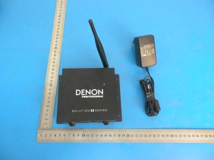
Click to zoom
Application Details
- Equipment Class
- DSS - Part 15 Spread Spectrum Transmitter
- Date of Grant
- Aug 01, 2015
- Application Purpose
- Original Equipment
- Date of Application
- Jul 30, 2015
- Equipment Note
- Wireless Audio Transmitter
- Frequency Range
- 2404.00000000 - 2476.00000000
- Company
- INMUSIC BRANDS INC
- Country
- United States
Documents & Files
Document Text
Text extracted from the exhibit documents filed with the FCC. Open a document above to read the original.
Users Manual
DN-202WT User Guide English ( 2 – 9 ) Guía del usuario Español ( 10 – 17 ) Guide d’utilisation Français ( 18 – 25 ) Guida per l’uso Italiano ( 26 – 33 ) Benutzerhandbuch Deutsch ( 34 – 41 ) A ppendix English ( 42 – 43 ) 2 User Guide ( English ) Introduction DN-202WT is a wireless audio transmi tter with professional-grade audio outputs. In conjunction with our DN-202WR wireless receivers, this lets you add wireless audio transmission to your audio system—reducing cables and clutter without reducing sound quality. Please see this guide’s Setup chapter to learn how to integrate DN- 202WT with your audio system. Box Contents DN-202WT User Guide Power Adapter Safety & Warranty Manual Support For the latest information about this product (system requirements, compatibility information, etc.) and product registration, visit denonpro.com . 3 Features STATUS ST. PAIR MONO DN-202WT 5V 3A DC R L PEAK 2.4GHZ WIRELESS AUDIO TRANSMITTER INPUT UNBAL. UNBAL. BAL. 2 2 3 4 5 1 6 7 88 7 1. Power Input: Use the included power adapter to connect this input to a power outlet. See Setup for more information. 2. Wireless Antenna: This antenna transmits the audio signal to a paired DN-202WR within range. DN-202WT has a transmission range of 100 feet (30.5 meters). 3. Pair Button: Press and hold this button for 3 seconds to make DN- 202WT available for pairing to a nearby DN-202WR. See Setup for more information. 3.4” (88mm) 4.6” (117mm) 1.7” (44mm) 4 4. Status Light: This LED indicates the DN-202WT’s pairing status: • Flashing slowly (approximately once per second) : DN-202WT is not paired to a DN-202WR. • Flashing quickly (approximately twice per second) : DN-202WT is “searching” for a DN-202WR. • Solidly lit: DN-202WT is paired to a DN-202WR. 5. Stereo / Mono Selector ( St. / Mono ) : Press this button to set the outgoing wireless audio signal to stereo (raised position) or mono (depressed position). Note: For stereo operation, make sure the left ( L ) and right ( R ) inputs are connected to left and right outputs, respectively. 6. Peak Lights: These LEDs light up when the incoming audio signal is “clipping” (distorting) at levels higher than 0 dB. If this happens, reduce the volume level of your audio source. 7. Inputs ( Balanced XLR ) : Use XLR cables to connect these inputs to your audio source (mixer, media player, etc.). See Setup for more information. 8. Inputs ( Unbalanced 1 / 4” / 6.35mm ) : Use 1/4” (6.35 mm) cables to connect these inputs to your audio source (mixer, media player, etc.). See Setup for more information. 5 Setup For an example of how you could set up DN-202WT, please see the Example diagram later in this section. Items not listed under Introduction > Box Contents are sold separately. Important: For stereo operation, make sure left and right inputs are connected to left and right outputs, respectively. Make sure DN-202WT and DN-202WR are within 100 feet (30.5 meters) of each other. Do not use DN-202WT near a microwave oven, which can interfere with the reception. 1. Use XLR cables or 1/4” (6.35mm) cables to connect DN-202WT’s inputs (balanced or unbalanced) to your mixer, media player, or other audio source. 2. Use the included power adapter to connect DN-202WT’s power input to a power outlet. It will power on immediately. 3. Connect your mixer, media player, or other audio source to a power outlet, and then power it on. 6 4. Use XLR cables or 1/4” (6.35mm) cables to connect your DN-202WR’s outputs (balanced or unbalanced) to your loudspeakers, mixer, amplifier, or other device that accepts line-level inputs (make sure this device is powered off ). 5. Use the included power adapter to connect DN-202WR’s power input to a power outlet. It will power on immediately. 6. Connect your loudspeakers, mixer, amplifier, or othe r output device to a power outlet, but do not power it on yet. 7. Press and hold the Pair button on DN-202WT for 3 seconds. Its Status Light will start flashing rapidly. 8. Within approximately 15 seconds, press and hold the Pair button on DN-202WR for 3 seconds. Its Status Light will start flashing rapidly. If you need to pair multiple DN-202WR units to DN-202WT, do this step with all of them within the 15 seconds. 9. Wait until the Status Lights on both DN-202WT and DN-202WR are solidly lit (not flashing), indicating that they are paired. 10. Power on your loudspeakers, mixer, amplifier, or other output devices. You can now use DN-202WT and DN-202WR to play audio wirelessly. 7 Example: INPUT UNBAL. UNBAL. BAL. OUTPUT UNBAL. UNBAL. BAL. Items not listed under Introduction > Box Contents are sold separately. PA loudspeakers Loudspeakers Microphones DN-202WT DN-202WR Mixer 8 Troubleshooting If you encounter a problem, try doing these things first: • Make sure all cables and other connected devices are properly and securely connected. • Make sure you are using DN-202WT as described in this User Guide . • Make sure your other devices or media are working properly. • If you believe DN-202WT is not working properly, check the following table for your problem and solution. Problem: Solution: Please see: Power does not turn on. Make sure DN-202WT’s power input is properly connected to a power outlet using the included power adapter. Setup DN-202WT does not produce any sound, or the sound is distorted. Make sure all cable and device connections are secure and correct. Make sure none of the cables are damaged. Make sure the settings on your loudspeaker, mixer, etc. are correct. Setup 9 Problem: Solution: Please see: DN-202WT does not pair to a DN-202WR or is having trouble maintaining a connection. Make sure the power inputs of the DN- 202WT and DN-202WR are properly connected to power outlets using the included power adapters. Make sure the DN-202WT and DN-202WR are within 100 feet (30.5 meters) of each other. If possible, remove any obstructions between DN-202WT and DN-202WR. If possible, power off or remove any nearby devices that transmit on a 2.4 GHz frequency. These devices …
Text truncated - open the document above for the full version.
Cover Letter(s)
July 17, 2015 Equipment Autorisation Division Federal Communications Commission 7435 Oakland Mills Road Columbia, MD 21046 FCC ID: Y4O-DX18_ Product Name: Wireless Audio Transmitter Request for Confidentiality Pursuant to Sections 0.457 and 0.459 of the commissions rules, we hereby request that the following documents be held confidential: Schematics Long-term confidential Block diagram Long-term confidential Operation description Long-term confidential These materials contain trade secrets and proprietary information and are not customarily released to the public. The public disclosure of this information might be harmful to the company and provide unjustified benefits to our competitors. Signature: Name Jacky Liao Position Saty/EMI Dept Manager Company Name InMusic Brands, Inc. Address 200 Scenic View Drive, Cumberland, RI 02864, U.S.A Tel +866-2-2717-2389 Fax +866-2-2717-2389 Email [email protected]
Cover Letter(s)
InMusic Brands, Inc. Differences Description We InMusic Brands, Inc. state: Product name: Wireless Audio Transmitter Model: DX18, DN-202WT All model’s the function, software and electric circuit are the same , only with a product model named different. Signature: 2015-07-17 Signatory Name Jacky Liao Position Saty/EMI Dept Manager Company Name InMusic Brands, Inc. Address 200 Scenic View Drive, Cumberland, RI 02864, U.S.A Te l +866-2-2717-2389 Fax +866-2-2717-2389 Email [email protected] only product model name is different.
ID Label/Location Info
LABEL LOCATION
RF Exposure Info
MPE Calculation Method E (V/m) = (30*P*G) 0.5 /d Power Density: Pd (W/m2) = E 2 /377 E = Electric Field (V/m) P = Peak RF output Power (W) G = EUT Antenna numeric gain (numeric) d = Separation distance between radiator and human body (m) The formula can be changed to Pd = (30*P*G) / (377*d 2 ) From the peak EUT RF output power, the minimum mobile separation distance, d=0.2m, as well as the gain of the used antenna, the RF power density can be obtained. Omni antenna gain is the biggest one and it is 3.3dBi Calculated Result and Limit (WORSE CASE IS AS BELOW) Antenna Gain (Numeric) Peak Output Power (mW) Power Density (S) (mW/cm2) Limit of Power Density (S) (mW/cm2) Test Result 1.995 (3dBi) 36.64 (15.64 dBm) 0.0146 1 Compiles
Test Report
Shenzhen Alpha Product Testing Co., Ltd. TEST REPORT FCC: Y4O-DX18 IC: 11215A-DX18 Applicant : InMusic Brands, Inc Address : 200 Scenic View Drive, Cumberland, RI 02864, U.S.A Equipment Under Test (EUT): Name : Wireless Audio Transmitter Model : DX18, DN-202WT Trademark : Standards : FCC PART 15, SUBPART C : 2014 (Section 15.247) RSS-247 ISSUE 1 MAY 2015; RSS-GEN ISSUE 4 NOV 2014 ANSI C63.4:2014 ; ANSI C63.10:2013 Report No : T1850593 05 Date of Test : June 03, 2015- June 10, 2015 Date of Issue : June 11, 2015 Tset Result : PASS In the configuration tested, the EUT complied with the standards specified above Authorized Signature (Mark Zhu) Manager The manufacture should ensure that all the products in series production are in conformity with the product sample detailed in this report. If the product in this report is used in any configuration other than that detailed in the report, the manufacturer must ensure the new system complies with all relevant standards. Any mention of Shenzhen Alpha Product Testing Co., Ltd. Or test done by Shenzhen Alpha Product Testing Co., Ltd. Approvals in connection with, distribution or use of the product described in this report must be approved by Shenzhen Alpha Product Testing Co., Ltd. Approvals in writing. Page 2 of 45 Report No.: T1850593 05 Contents 1. General Information ............................................................................................................... 5 1.1. Description of Device (EUT) ...............................................................................5 1.2. Accessories of device (EUT) ...............................................................................6 1.3. Test Lab information ............................................................................................6 2. Summary of test ...................................................................................................................... 7 2.1. Summary of test result .........................................................................................7 2.2. Assistant equipment used for test .........................................................................8 2.3. Block Diagram .....................................................................................................8 2.4. Test mode .............................................................................................................8 2.5. Test Conditions .....................................................................................................9 2.6. Measurement Uncertainty (95% confidence levels, k=2) ....................................9 2.7. Test Equipment ...................................................................................................10 3. Maximum Peak Output power ............................................................................................ 11 3.1. Limit ................................................................................................................... 11 3.2. Test Procedure .................................................................................................... 11 3.3. Test Setup ........................................................................................................... 11 3.4. Test Result .......................................................................................................... 11 4. Bandwidth ............................................................................................................................. 12 4.1. Limit ...................................................................................................................12 4.2. Test Procedure ....................................................................................................12 4.3. Test Result ..........................................................................................................12 5. Carrier Frequency Separation ............................................................................................. 15 5.1. Limit ...................................................................................................................15 5.2. Test Procedure ....................................................................................................15 5.3. Test Result ..........................................................................................................15 6. Number Of Hopping Channel ............................................................................................. 16 6.1. Limit ...................................................................................................................16 6.2. Test Procedure ....................................................................................................16 6.3. Test Result ..........................................................................................................16 7. Dwell Time ............................................................................................................................. 17 7.1. Test limit ............................................................................................................17 7.2. Test Procedure ....................................................................................................17 7.3. Test Results ........................................................................................................17 8. Radiated emissions ................................................................................................................ 19 8.1. Limit ...................................................................................................................19 8.2. Block Diagram of Test setup ..............................................................................20 8.3. Test Procedure ....................................................................................................21 8.4. Test Result ........................................…
Text truncated - open the document above for the full version.
Test Setup Photos
Photos of Radiated emission Photos of Conducted Emission test
Contact Information
Applicant
Hill Lien(Director of Compliance)
Test Firm
Shenzhen Alpha Product Testing Co., Ltd.Mark Zhu
Technical Specifications
| # | Rule Parts | Frequency Range | Power Output |
|---|---|---|---|
| 1 | 15C | 2.40 GHz - 2.48 GHz | 36.64 mW |
Other Applications from INMUSIC BRANDS INC
Y4O-LDT2
Jul 22, 2026Streaming Module w/Mic and Kick Trigger
Equipment Class
DSS - Part 15 Spread Spectrum TransmitterY4O-NK54
Apr 16, 2026Ultra-Portable 2-Deck DJ Controller w/ Stem Control
Equipment Class
DTS - Digital Transmission SystemY4O-NK55
Apr 16, 2026Portable 2-Deck DJ Controller w/ Party Lights, and Stem Control
Equipment Class
DTS - Digital Transmission SystemY4O-ACVC
Nov 28, 2025Audio Device
Equipment Class
DTS - Digital Transmission SystemY4O-RMZ2
Nov 27, 2025Audio Device
Equipment Class
DSS - Part 15 Spread Spectrum Transmitter