Y4YLONGBOWLONGBOW
Peak Gain Systems Inc.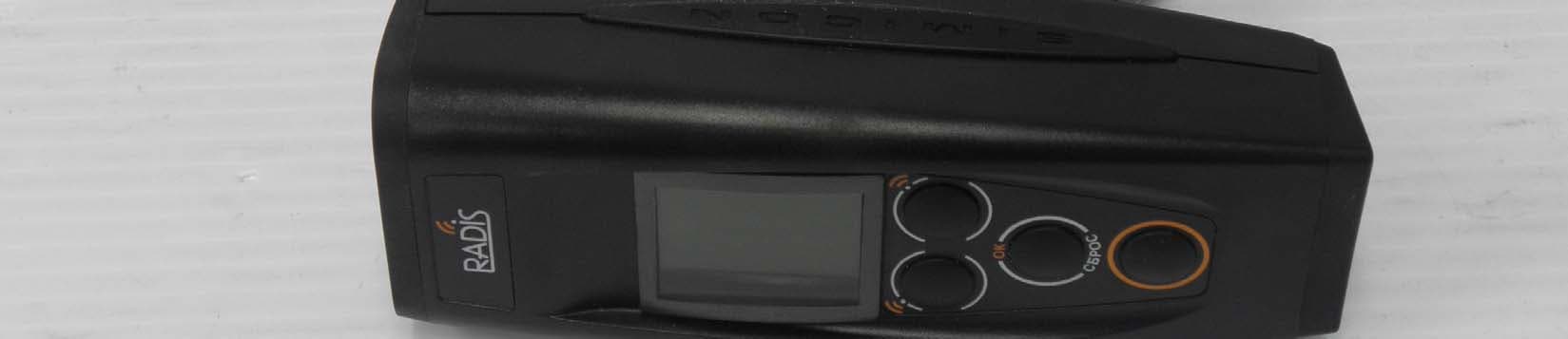
Click to zoom
Application Details
- Equipment Class
- FDS - Part 15 Field Disturbance Sensor
- Date of Grant
- Feb 17, 2011
- Application Purpose
- Original Equipment
- Date of Application
- Feb 16, 2011
- Equipment Note
- LONGBOW
- Frequency Range
- 24155.00000000 - 24155.00000000
- Company
- Peak Gain Systems Inc.
- Country
- Canada
Documents & Files
Document Text
Text extracted from the exhibit documents filed with the FCC. Open a document above to read the original.
Users Manual
Note: This equipment has been tested and found to comply with the limits of a Class B digital device, pursuant to part 15 of the FCC rules. These limits are designed to provide reasonable protection against harmful interference in commercial installation. This equipment generates, uses and can radiate radio frequency energy and, if not installed and used in accordance with the instructions, may cause harmful interference to radio communications. However, there is no guarantee that interference will not occur in a particular installation. If this equipment does cause harmful interference to radio or television reception which can be determined by turning the equipment off and on, the user is encouraged to try to correct the interference by one or more of the following measures: • Reorient or relocate the receiving antenna • Increase the separation between the equipment and receiver • Connect the equipment into an outlet on a circuit that is different from that which the receiver is connected • Consult the dealer or an experienced radio/TV technician for help. Changes or modifications not expressly approved by the party responsible for compliance could void the user’s authority to operate the equipment. This device compiles with Part 15 of the FCC Rules. Operation is subject to the following two conditions: (1) This device may not cause harmful interference (2) This device must accept any interference received, including interference that may cause undesired operation
Cover Letter(s)
DATE : January 28, 2011 Equipment Autorisation Division Federal Communications Commission 7435 Oakland Mills Road Columbia, MD 21046 FCC ID: Y4YLONGBOW Product Name: LONGBOW Request for Confidentiality Pursuant to Sections 0.457 and 0.459 of the commissions rules, we hereby request that the following documents be held confidential: • Block diagram • Schematics • Parts Lists These materials contain trade secrets and proprietary information and are not customarily released to the public. The public disclosure of this information might be harmful to the company and provide unjustified benefits to our competitors. Dated this 28 Day of January Year 2011 By: Cory Woodrow Signature Printed Title: President On behalf of : Peak Gain Systems Inc Telephone: 647-291-0357
Operational Description
Operating principle of the Longbow radar gun is based on the Doppler Effect involving a Doppler frequency shift of a radar signal during reflection from a moving object. Doppler frequency shift is proportional to the object speed; therefore the speed measurement consists of the difference measurement between frequencies of the radiated signal and returned signal from the target. Digital low-frequency signal's processing based on Fourier transformation is used for the spectrum analysis and for frequency value measurements.The full spectrum analysis functions to provide singling out the fastest target speed against a background of slower targets and to measure both the patrol car speed and the target speed while moving or stationary. Two independent channels are used for selection of targets by the direction of their movement. Measurement of the relative phase shift between the Doppler signals of two channels allows for making the determination of the target movement direction. Output signals from two channels are entered into digital memory where these signals are saved, and further processed to obtain information on the targets’ speeds. When receiving information about the measured speeds, the digital data is displayed on the LED indicator and on the LCD display. After each measurement cycle the microwave oscillator is switched off, which allows to reduce consumed power of the police radar gun and to increase the noise immunity of the device. The firmware programming also governs the information distribution and storage in RAM, the measurement of time elapsed from the speed reading being captured, and its indication. Furthermore, the CPU and its programming provides the radar operating mode setting and performs a number of service functions, including monitoring of the power source condition. The instrument is encased in a shockproof plastic case. The front and rear parts of the instrument are safeguarded by elastic rubber protectors. A dielectric lens of the transceiver antenna is mounted in the front part of the casing A microwave unit consisting of the oscillator, mixers, waveguide channel and horn antenna is installed in the case of the police radar gun. A circuit board containing amplifiers is mounted on the microwave unit. The antenna is a conical horn, gunn diode based antenna. The polarization is circular, and has a gain of 19dBi. It is designed to produce an unmodulated output of 24.15 ± 0.10GHz. The CPU continuously monitors the trigger switch. Upon activation of the trigger, the antenna emits the specified radio energy. The RF energy is then reflected from the target vehicle (if present) and is received back at the antenna. This received signal is then mixed in the receiver diodes, extracting the doppler shift. The signal is then amplified, and digitized by a stereo A/D converter. The digitized signal is then analyzed by the CPU using digital signal processing techniques. If a valid target or targets are present, the relevant data is displayed on both the LED and LCD displays.
Test Report
Nemko Canada Inc. 303 River Road, Ottawa, Ontario K1V 1H2 T 1 613 737 9680 F 1 613 737 9691TF 1 800 563 6336 Nemko Test Report: 159822-1TRFWL Applicant: Peak Gain Systems Inc. 31 Blue Grouse Road Vaughan, ON Canada, L6A 4B8 Apparatus: Traffic Radar FCC ID: Y4YLONGBOW In Accordance With: FCC Part 15 Subpart C, 15.245 Operation within the bands 902-928 MHz, 2435- 2465 MHz, 5785-5815 MHz, 10500-10550 MHz and 24075-24175 MHz Authorized By: Sim Jagpal, General Manager Date: February 10, 2011 Total Number of Pages: 17 Email [email protected] Web www.nemko.com Nemko Canada Inc. Report Number: 159822-1TRFWL Specification: FCC Part 15 Subpart C, 15.245 TABLE OF CONTENTS Section 1 : Report Summary......................................................................................................................3 Section 2 : Equipment Under Test.............................................................................................................4 2.1 Identification of Equipment Under Test (EUT)..........................................................................................4 2.2 Accessories.................................................................................................................................................4 2.3 EUT Description.........................................................................................................................................4 2.4 Technical Specifications of the EUT..........................................................................................................5 2.5 EUT Setup diagram....................................................................................................................................5 2.6 Operation of the EUT during testing..........................................................................................................5 2.7 Modifications incorporated in the EUT ......................................................................................................5 Section 3 : Test Conditions.........................................................................................................................6 3.1 Specifications.............................................................................................................................................6 3.2 Deviations From Laboratory Test Procedures ............................................................................................6 3.3 Test Environment.......................................................................................................................................6 3.4 Measurement Uncertainty...........................................................................................................................6 3.5 Test Equipment...........................................................................................................................................7 Section 4 : Results Summary.....................................................................................................................8 4.1 FCC Part 15 Subpart C : Test Results........................................................................................................8 Appendix A : Test Results..........................................................................................................................9 Clause 15.207(a) Powerline Conducted Emissions...............................................................................................9 Clause 15.209(a) Radiated Emissions within Restricted Bands..........................................................................12 Clause 15.215(c) 20dB Bandwidth......................................................................................................................13 Clause 15.245(b) Radiated emissions not in Restricted Bands............................................................................14 Appendix B : Setup Photographs............................................................................................................16 Appendix C : Block Diagram of Test Setups..........................................................................................17 Page 2 of 17 SECTION 1 : REPORT SUMMARY Nemko Canada Inc. Report Number: 159822-1TRFWL Specification: FCC Part 15 Subpart C, 15.245 Section 1 : Report Summary These tests were conducted on a sample of the equipment for the purpose of demonstrating compliance with Part 15, Subpart C. Radiated tests were conducted in accordance with ANSI C63.4-2003. The assessment summary is as follows: Apparatus Assessed: Traffic Radar Specification: FCC Part 15 Subpart C, 15.245 Compliance Status: Complies Exclusions: None Non-compliances: None Report Release History: Original Release Test Location: Nemko Canada Inc. 303 River Road Ottawa, Ontario K1V 1H2 Registration Number: 176392 (3m Semi-Anechoic Chamber) Tests Performed By: Kevin Ma, Technical Assessor Test Dates: December 13-15, 2010 Note that the results contained in this report relate only to the items tested and were obtained in the period between the date of initial receipt of samples and the date of issue of the report. This test report has been completed in accordance with the requirements of ISO/IEC 17025. All results contain in this report are within Nemko Canada’s ISO/IEC 17025 accreditation. Nemko Canada Inc. authorizes the applicant to reproduce this report provided it is reproduced in its entirety and for use by the company’s employees only. Any use which a third party makes of this report, or any reliance on or decisions to be made based on it, are the responsibility of such third parties. Nemko Canada Inc. accepts no responsibility for damages, if any, suffered by any third party as a result of decisions made or actions based on this report. Page 3 of 17 SECTION 2 : EQUIPMENT UNDER TEST Nemko Canada Inc. Report Number: 159822-1TRFWL Specification: FCC Part 15 Subpart C, 15.245 Section 2 : Equipment …
Text truncated - open the document above for the full version.
Contact Information
Applicant
Cory Woodrow(President)
Technical Contact
Peak Gain Systems Inc.Cory Samuel Woodrow
[email protected]647-291-0357
31 Blue. Grouse Road · Vaughan · Canada
Test Firm
Nemko Canada Inc. (Ottawa)Charles Neal
Technical Specifications
| # | Rule Parts | Frequency Range | Power Output |
|---|---|---|---|
| 1 | 15.245 | 24.16 GHz - 24.16 GHz | - |