Y5BIONML1G2GPRS Module with Intergrated GPS
IONIT Global Inc.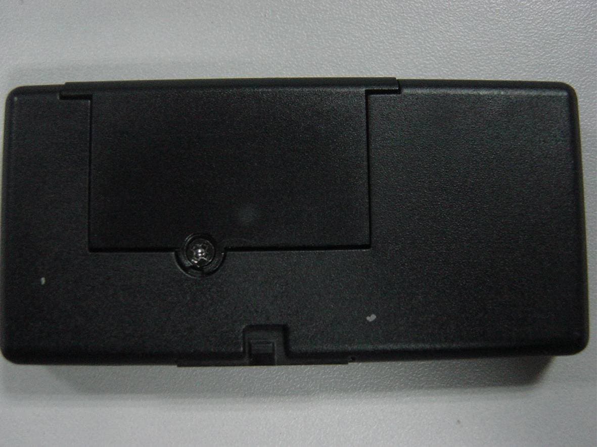
Click to zoom
Application Details
- Equipment Class
- PCB - PCS Licensed Transmitter
- Date of Grant
- Jan 16, 2011
- Application Purpose
- Original Equipment
- Date of Application
- Jan 10, 2011
- Equipment Note
- GPRS Module with Intergrated GPS
- Frequency Range
- 1850.20000000 - 1909.80000000
- Company
- IONIT Global Inc.
- Country
- China
Documents & Files
Document Text
Text extracted from the exhibit documents filed with the FCC. Open a document above to read the original.
Users Manual
User manual of ION 1 Module Model No: IONML1G2 1. Appearance of module Weight (in g): 6g (typical) Power supply: External input : 3.4V to 4.2V Temperature range: Normal range: -10°C to +70°C (full compliant) Physical dimension:36 .0 x 31.8 x 2.40 mm 2. Overview This design is based mainly on GSM/GPRS wireless module, which build in the GPS module. The module provides GSM mobile communication capability and suitable for embedding in some wireless products, such as wireless modem, PDAs and other devices. In addition, The module has an embedded Powerful TCP/IP protocol stack, and it allows you access to the Internet easier and convenient. The build in GPS module allows you receive GPS signal for pathfinding,and so on. 3. Technical Specifications 3.1 Power VIN: • 6.0 – 15.0VDC (Main) • 2.8 – 4.2VDC (Expansion) Main: • Shutdown: < 50μA • Standby: < 800μA (GSM Idle) • GPS acquisition: < 8.0mA (GSM Idle) • GPS tracking: < 6.0mA (GSM Idle) • GSM dedicated: < 92.0mA (GPS Off) • GPRS max power: < 183.0mA (GPS Off) • Peak instantaneous: < 740mA Exp: 2.45 x Main 3.2 Environment Temperature: • -40 to 85° C Operation • -50 to +100° C Storage Humidity: • 20% to 90% Operation • 10% to 95% Storage ESD: 15KV immune on all user accessible surfaces and ports Altitude: -500 to +18,000m Shock: TBD Vibration: TBD 4. Declaration Change the device without permission is strictly prohibited. This user manual is just for the integrators reference. Issued Date: 31 Dec, 2010 FCC RF Exposure requirements: RF exposure information: To maintain compliance with FCC RF exposure requirements, use handset that maintain a 20cm separation distance between the user's body and the host. MPE limit for RF exposure at prediction frequency is 0.558mW/cm 2 for GSM850MHz and1mW/cm 2 for GSM1900MHz. The MPE for GSM850MHz is 0.512 mW/cm 2 and 0.244mW/cm 2 for GSM1900MHz. It satisfy RF exposure compliance. This device complies with part 15 of the FCC rules. Operation is subject to the following two conditions: (1) this device may not cause harmful interference, and (2) this device must accept any interference received, including interference that may cause undesired operation. NOTE: The manufacturer is not responsible for any radio or TV interference caused by unauthorized modifications to this equipment. Such modifications could void the user’s authority to operate the equipment.
Cover Letter(s)
IONT Global Inc. +1.949.867.1459(USA) +86.21.64852695(China) www.ionitglobal.com +852.9236.2213(Hong Kong) +86.21.64850078(Fax) Date: 15 December, 2010 To: Federal Communications Commission, Authorization & Evaluation Division, 7435 Oakland Mills Road, Columbia, MD 21046 To Whom It May Concern: The IONIT Global Inc., the undersigned, hereby authorizes Mr. Wu Xuewen from Shenzhen Morlab Communications Technology Co., Ltd., to act on the behalf of the IONIT Global Inc. solely in matters relating to the application for an FCC equipment authorization for FCC ID: Y5BIONML1G2 including the signing of documents in connection with this Application. Necessary acts carried out by Shenzhen Morlab Communications Technology Co., Ltd. on our behalf of the IONIT Global Inc. in connection with the Application shall have the same effect as acts of the IONIT Global Inc.. The IONIT Global Inc. also hereby certify that no party to this application is subject to a denial of benefits, including FCC benefits, pursuant to Section 5301 of the Anti-Drug Abuse Act of 1988, 21 U.S.C. 853(a). Thank you for your attention to this matter. Yours Sincerely, Hao Xu TS Manager
Cover Letter(s)
IONT Global Inc. +1.949.867.1459(USA) +86.21.64852695(China) www.ionitglobal.com +852.9236.2213(Hong Kong) +86.21.64850078(Fax) Date: 15 December, 2010 To: Federal Communications Commission, Authorization & Evaluation Division, 7435 Oakland Mills Road, Columbia, MD 21046 RE: IONIT Global Inc. FCC ID: Y5BIONML1G2 FCC Part 22&24 Certification Confidentiality Request Gentlemen: This letter is to comply with 47 CFR 0.457 and 0.459 pertaining to confidentiality material. IONIT Global Inc. requests that the following documents regarding this submission for FCC ID: Y5BIONML1G2 be kept confidential: Exhibit Type File Name Block Diagram IONML1G2_Block Diagram.pdf Schematics IONML1G2_Schematics.pdf Operational Description IONML1G2_Operational Description.pdf Part list IONML1G2_BOM.pdf Tune-Up-Procedure IONML1G2_Tune up procedure.pdf Those documents contain detailed system and equipment description and related information about the product which IONIT Global Inc. considers to be confidential proprietary, a custom design and, otherwise, not releasable to the general public. Since this design is a basis form which future technological products will evolve, IONIT Global Inc. considers this information would be of benefit to its competitors, and that the disclosure of the information in these documents would give competitors an unfair advantage in the market. Thank you for your attention to this matter. Yours Sincerely, Hao Xu TS Manager
Cover Letter(s)
IONT Global Inc. +1.949.867.1459(USA) +86.21.64852695(China) www.ionitglobal.com +852.9236.2213(Hong Kong) +86.21.64850078(Fax) To Whom It May Concern: The IONIT Global Inc., the undersigned, declared that the model IONML1G2 (FCC ID: Y5BIONML1G2) support Qual-band GSM bands, but 900MHz and 1800MHz bands cannot be used in American. Thank you for your attention to this matter. Yours Sincerely, Hao Xu TS Manager
Cover Letter(s)
Request for Modular Approval FCC ID: Y5BIONML1G2 Item Requirements EUT 1 The final device is designed for mobile or fixed operation (Portable is not permitted – Reference TCB Exclusion List (17 July 2002) II (g)). This module will be installed in automotive product where the transmitting antenna provides 20cm separation distance from human body. 2 The maximum antenna gain to allow compliance with RF exposure requirements is listed on the Grant of Certification for the module. The antenna is built-in modular, antenna gain not exceed 3 dBi. MPE value is 0.512mW/cm 2 for celluar band and 0.24 mW/cm 2 for PCS band, above MPE estimate is based upon the measured peak conducted output power. MPE estimate is submitted via separate RF exposure attachment. 3 The licensed module must have a FCC ID label on the module itself. That FCC ID label must be visible through a window on the final device or it must be visible when an access panel, door or cover is easily removed. If not, a second label must be placed on the outside of the final device that contains the following text: Contains “FCC ID: Y5BIONML1G2” Please refer to the FCC ID label format. Labeling instruction has been provided in the OEM installation instruction. 4 The Grant should include the following words in the device description or grant notes: “modular transmitter” or “transmitter module”. Modular approval is requested for this application.
External Photos
External Photos 1. Front View of EUT 2. Back View of EUT 3. Side View of EUT
ID Label/Location Info
Label Label Location
Internal Photos
Internal Photos
RF Exposure Info
FCC ID: Y5BIONML1G2 Page 1 of 2 Prediction of MPE limit at given distance Product Descritpion: GPRS Module with Intergrated GPS Type: IONML1G2 1. Introduction Equation from page 18 of OET Bulletin 65, Edition 97-01 Where: S = power density P = power input to the antenna G = power gain of the antenna in the direction of interest relative to an isotropic radiator R = distance to the center of radiation of the antenna 2. Limits for Maximum Permissible Exposure According to FCC Part 1.1307, systems operating under the provisions of this section shall be operated in a manner the ensures that the public is not exposed to radio frequency energy level in excess of the commission’s guidelines. According to FCC Part 1.1310 RF exposure is calculated. Limits for General Population/ Uncontrolled Exposure Limits for General Population/ Uncontrolled Exposure Frequency Range (MHz) Electric Field Strength(E)(V/m) Magnetic Field Strength (H)(A/m) Power Density (S)(mW/cm 2 ) 0.3-1.34 614 1.63 (100)* 1.34-30 824/f 2.19/f (180/f2)* 30-300 27.5 0.073 0.2 300-1500 f/1500 1500-100,000 1.0 FCC ID: Y5BIONML1G2 Page 2 of 2 3. Test result GSM 850MHz Maximum peak output power at antenna input terminal(dBm): 31.11 Antenna Gain (typical) (dBi): 3 PG(mW): 2576 Prediction distance(cm): 20 Predication frequency(MHz): 836.5 Power density at predication frequency at 20 cm(mW/cm 2 ): 0.512 MPE limit for RF exposure at prediction frequency(mW/cm 2 ): 0.558 GSM 1900MHz Maximum peak output power at antenna input terminal(dBm): 30.88 Antenna Gain (typical) (dBi): 3 PG(mW): 1225 Prediction distance(cm): 20 Predication frequency(MHz): 1880 Power density at predication frequency at 20 cm(mW/cm 2 ): 0.24 MPE limit for RF exposure at prediction frequency(mW/cm 2 ): 1.0 4. Conclusion Test result is passed.
Test Report
Report No.: SZ10110149E01 Page 2 of 35 TABLE OF CONTENTS 1. TEST CERTIFICATION ........................................................................................................... 3 2. GENERAL INFORMATION .................................................................................................... 4 2.1 EUT Description ......................................................................................................................... 4 2.2 Test Standards and Results ........................................................................................................ 5 2.3 Facilities and Accreditations ...................................................................................................... 6 3. 47 CFR PART 2, PART 22H & 24E REQUIREMENTS ........................................................ 7 3.1. Conducted RF Output Power .................................................................................................... 7 3.2 99% Occupied Bandwidth ....................................................................................................... 11 3.3 Frequency Stability ................................................................................................................... 15 3.4 Conducted Out of Band Emissions ......................................................................................... 17 3.5 Band Edge ................................................................................................................................. 21 3.6 Transmitter Radiated Power (EIRP/ERP) ............................................................................. 24 3.7 Radiated Out of Band Emissions ............................................................................................ 29 Change History Issue Date Reason for change 1.0 December 27, 2010 First edition Report No.: SZ10110149E01 Page 4 of 35 2. GENERAL INFORMATION 2.1 EUT Description EUT Type ............................. : GPRS Module with Integrated GPS Model Name ......................... : IONML1G2 Serial No. .............................. : (n.a, marked #1 by test site) Hardware Version ................. : 1.0 Software Version .................. : 1.0 Frequency Range .................. : GSM 850MHz: Tx: 824.20 - 848.80MHz (at intervals of 200kHz); Rx: 869.20 - 893.80MHz (at intervals of 200kHz) GSM 1900MHz: Tx: 1850.20 - 1909.80MHz (at intervals of 200kHz); Rx: 1930.20 - 1989.80MHz (at intervals of 200kHz) Modulation Type................... : GMSK Emission Designators ........... : 300KGXW Power Supply ....................... : Power Supply by DC 8V Note 1: The transmitter (Tx) frequency arrangement of the Cellular 850MHz band used by the EUT can be represented with the formula F(n)=824.2+0.2*(n-128), 128<=n<=251; the lowest, middle, highest channel numbers (ARFCHs) used and tested in this report are separately 128 (824.2MHz), 190 (836.6MHz) and 251 (848.8MHz). Note 2: The transmitter (Tx) frequency arrangement of the PCS 1900MHz band used by the EUT can be represented with the formula F(n)=1850.2+0.2*(n-512), 512<=n<=810; the lowest, middle and highest channel numbers (ARFCHs) used and tested in this report are separately 512 (1850.2MHz), 661 (1880.0MHz) and 810 (1909.8MHz). Note 3: The GPRS was tested under4 uplink time slots mode. Note 4: For a more detailed description, please refer to Specification or User’s Manual supplied by the applicant and/or manufacturer. Report No.: SZ10110149E01 Page 5 of 35 2.2 Test Standards and Results The objective of the report is to perform testing according to 47 CFR Part 2, Part 22 and Part 24 for the EUT FCC ID Certification: No. Identity Document Title 1 47 CFR Part 2 (10-1-09 Edition) Frequency Allocations and Radio Treaty Matters; General Rules and Regulations 2 47 CFR Part 22 (10-1-09 Edition) Public Mobile Services 3 47 CFR Part 24 (10-1-09 Edition) Personal Communications Services Test detailed items/section required by FCC rules and results are as below: No. Section Description Result 1 2.1046 Conducted RF Output Power PASS 2 2.1049 20dB Occupied Bandwidth PASS 3 2.1055 22.355 24.235 Frequency Stability PASS 4 2.1051 2.1057 22.917 24.238 Conducted Out of Band Emissions PASS 5 2.1051 2.1057 22.917 24.238 Band Edge PASS 6 22.913 24.232 Transmitter Radiated Power (EIPR/ERP) PASS 7 2.1053 2.1057 22.917 24.238 Radiated Out of Band Emissions PASS Report No.: SZ10110149E01 Page 6 of 35 2.3 Facilities and Accreditations 2.3.1 Facilities Shenzhen Morlab Communications Technology Co., Ltd. Morlab Laboratory is a testing organization accredited by China National Accreditation Service for Conformity Assessment (CNAS) according to ISO/IEC 17025. The accreditation certificate number is L3572. All measurement facilities used to collect the measurement data are located at 3/F, Electronic Testing Building, Shahe Road, Xili, Nanshan District, Shenzhen, 518055 P. R. China. The test site is constructed in conformance with the requirements of ANSI C63.7, ANSI C63.4 and CISPR Publication 22; the FCC registration number is 741109. 2.3.2 Test Environment Conditions During the measurement, the environmental conditions were within the listed ranges: Temperature (°C): 15 - 35 Relative Humidity (%): 30 -60 Atmospheric Pressure (kPa): 86-106 Report No.: SZ10110149E01 Page 7 of 35 3. 47 CFR PART 2, PART 22H & 24E REQUIREMENTS 3.1. Conducted RF Output Power 3.1.1 Requirement According to FCC section 2.1046(a), for transmitters other than single sideband, independent sideband and controlled carrier radiotelephone, power output shall be measured at the RF output terminals when the transmitter is adjusted in accordance with the tune-up procedure to give the values of current and voltage on the circuit elements specified in FCC section 2.1033(c)(8). 3.1.2 Test Description 1. Test Setup: The EUT, which is powered by the Battery, is coupled to the Spectrum Analyzer (SA) and the System Simulator (SS) with Attenuators through the Power Splitter; the…
Text truncated - open the document above for the full version.
Test Setup Photos
Test Setup Photos 1. CSE 2. RSE
Contact Information
Applicant
Hao Xu(TS Manager)
Technical Contact
Shenzhen Morlab Communications Technology Co.,LtdWu Xuewen
FL.3,Electronic Testing Bld, Shahe Rd · Shenzhen · China
Test Firm
Shenzhen Morlab Communications Technology Co.,LtdShu Luan
Technical Specifications
| # | Rule Parts | Frequency Range | Power Output | Emission | Tolerance |
|---|---|---|---|---|---|
| 2 | 24E | 1.85 GHz - 1.91 GHz | 520.00 mW | 255KGXW | 0.1 ppm |