Y5JEA1103Easy Assist Call Button
Alert Technologies, Inc.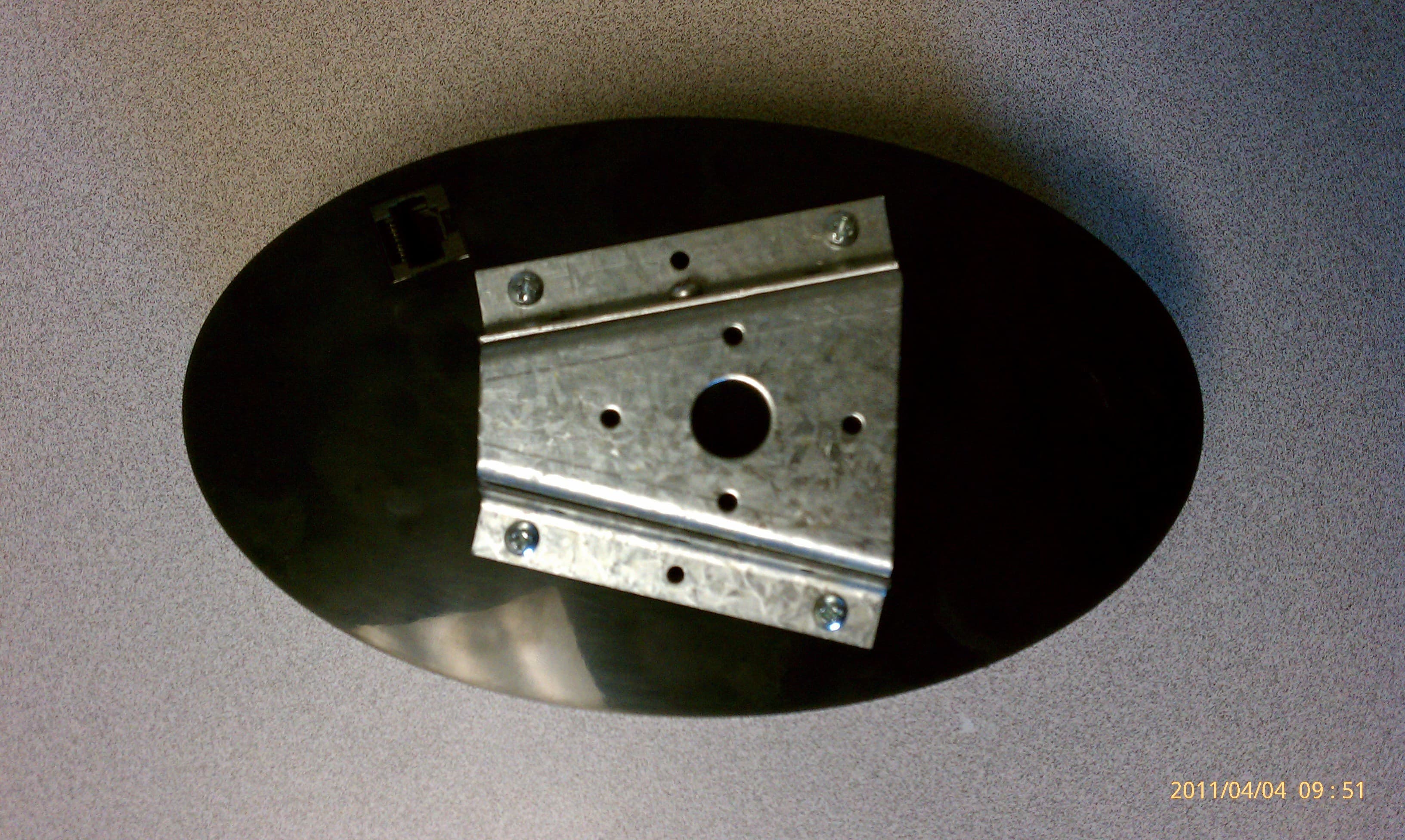
Click to zoom
Application Details
- Equipment Class
- TNB - Licensed Non-Broadcast Station Transmitter
- Date of Grant
- May 01, 2011
- Application Purpose
- Original Equipment
- Date of Application
- Apr 27, 2011
- Equipment Note
- Easy Assist Call Button
- Frequency Range
- 450.00000000 - 470.00000000
- Company
- Alert Technologies, Inc.
- Country
- United States
Documents & Files
Document Text
Text extracted from the exhibit documents filed with the FCC. Open a document above to read the original.
Users Manual
EasyAssist Direct to Radio Call Button Operating Manual NOTES: Table of Contents Contents Introduction............................................................................4 RF Safety and FCC Information............................................5 Industry Canada Information.................................................6 Safety and Information..........................................................7 EasyAssist Controls..............................................................8-9 Getting Started......................................................................10 Installing the Batteries................................................10 Recording...................................................................11 Volume.......................................................................12 Locking.......................................................................13 Mounting.....................................................................14-15 Trouble Shooting...................................................................16 Advanced Operation..............................................................17 Frequency and CTCSS controls.................................17 Frequency and CTCSS input examples.....................18 Frequency Chart.........................................................19 CTCSS Chart..............................................................20 Table of Contents Introduction Thank you for purchasing the Alert Technologies EasyAssist. The EasyAssist was designed for easy deployment, maintenance, durability, and rock solid operation for years. We encourage you to consider the various areas in your facility that would benefit from the EasyAssist. Any place you have a need for 2-Way radio communications, you can quickly add efficiencies with the deployment of the EasyAssist. Once again thank you for purchasing a product completely Made in the USA by people who care about what they do and how it benefits the people around the country and the world. Very best regards, Alert Technologies, Inc. Introduction RF Safety and Compliance RF Safety and FCC Compliance EasyAssist is a device that complies with part 15 of the FCC rules. Operation is subject to the condition that this device does not cause harmful interference. Federal Communications Commission 445 12th Street, SW Washington, DC 20554 1-888-225-5322 (1-888-CALL FCC) Voice: toll-free 1-888-835-5322 (1-888-TELL FCC) TTY: toll-free You may be required to obtain and maintain a license from the FCC to operate this device in your environment. Please contact the FCC via the following contact information to ensure your compliance. Changes or modifications not expressly approved by the manufacturer could void the user’s authority to operate the equipment. Canadian Compliance For Canadian Regulations and Compliance contact: Industry Canada C.D. Howe Building 235 Queen Street Ottawa, Ontario K1A 0H5 Canada Toll-free: 1-800-328-6189 (Canada) Canadian Compliance EasyAssist is a device that complies with part Industry Canada rules. Operation is subject to the condition that this device does not cause harmful interference. You may be required to obtain and maintain a license from the FCC to operate this device in your environment. Please contact the FCC via the following contact information to ensure your compliance. Changes or modifications not expressly approved by the manufacturer could void the user’s authority to operate the equipment. The EasyAssist requires care in mounting and servicing. Observing the following precautions will ensure the proper function and safety of the unit. - Do not screw through the device to mount to a surface. - Keep the EasyAssist away from water, high moisture, or high temperatures. - This equipment contains potentially hazardous voltages. Do not attempt to disassemble the unit. - Excepting the batteries this unit contains absolutely no user serviceable components and all service should be completed only by qualified service personnel. - Do not dispose of batteries in fire. The batteries may explode. - Do not open or mutilate the batteries, they contain dangerous electrolytes. - Operating this unit in any capacity other than its intended purpose may result in system failure and possible injury. Safety and Information CAUTION! Available Controls and Components FRONT 1. Volume Up and Down 2. Message (Play)back 3. (Forward) to next message 4. (Wakeup) the unit from sleep 5. (Erase) the selected message 6. (Record) the current message 7. (Mic) is the microphone location 8. (Freq and Code Select) 9. (Options Selections) 10. Speaker 11. Call Button 12. Shield Mount BACK 1. Mounting Bracket 2. Mounting Bracket Lock Screw 3. Auxillery Call Button or Power Jack EasyAssist Controls EasyAssist Controls Front Back 1 2 34 56 7 89 12 2 3 1 11 10 Installing the Batteries 1. Insert any coin into the slot on the side of the battery door. 2. Firmly twist the coin to remove the battery door. 3. Locate the colored dot on end of the battery sled. 4. Insert the dotted end of the sled first until it reaches the back and then firmly press down to latch the sled in place. (fig. 1) 5. The EasyAssist should wake up and the front button should flash three (3) times. 6. Locate the battery sled retaining post on the battery door and align it to the top of the EasyAssist. Setup Process - Install batteries - Record messages - Adjusting the volume - Lock unit controls - Mount to wall - Test operation (fig. 1) The Easy Assist system will support up to 6 messages of 10 seconds each. The system expects the following message order each message can be accessed by pressing (wakeup) and then counting the number of times the button flashes. Pressing (Wakeup) will display the number of flashes associated with the current message. Message 1 (1 flash) : Call Button local (non-radio) announcement. Message 2 (2 flashes): Call Button radio broadcast message. Message 3 (3 flashes): Message 3: Aux Button radi…
Text truncated - open the document above for the full version.
External Photos
FRONT View with Customer Controls Visible BOTTOM View TOP View LEFT Side RIGHT Side BACK with Mounting Bracket
ID Label/Location Info
FCC ID: Y5JEA1103 This device complies with part 15 of the FCC Rules. Opera$on is subject to the condi$on that this device does not cause harmful interference.
Internal Photos
Base with power and programming cable connected Base Only Inside Top with PCB, antenna, speaker and touchpad connected Flip side of the PCB RF Module without shield
RF Exposure Info
Project 12116-10 Prepared for: Alert Technologies, Inc. 16441 Space Center Blvd. Bldg. D-500 Houston, Texas 77058 By Professional Testing (EMI), Inc. 1601 N. A.W. Grimes Blvd., Suite B Round Rock, Texas 78665 April 19, 2011 MPE / RF Exposure Report Easy Assist Call Button Y5JEA1103 12116-10 Page 2 of 5 Table of Contents Title Page ........................................................................................................................................1 Table of Contents ...........................................................................................................................2 Certificate of Compliance..............................................................................................................4 1.0 MPE Prediction ...................................................................................................................4 1.1 Evaluation Procedure .......................................................................................................4 1.2 Evaluation Criteria ...........................................................................................................4 NOTICE: (1) This Report must not be used to claim product endorsement, by NVLAP, NIST, the FCC or any other Agency. This report also does not warrant certification by NVLAP or NIST. (2) This report shall not be reproduced except in full, without the written approval of Professional Testing (EMI), Inc. (3) The significance of this report is dependent on the representative character of the test sample submitted for evaluation and the results apply only in reference to the sample tested. The manufacturer must continuously implement the changes shown herein to attain and maintain the required degree of compliance. 12116-10 Page 3 of 5 Applicant: Alert Technologies, Inc. Applicant’s Address: 16441 Space Center Blvd., Bldg. D-500 Houston, Texas 77058 FCC ID: Y5JEA1103 Project Number: 12116-10 Test Dates: January 27, 2011; February 8 & 10, April 15, 2011 I, Layne Lueckemeyer, for Professional Testing (EMI), Inc., being familiar with the FCC rules and test procedures have reviewed the test setup, measured data and this report. I believe them to be true and accurate. Layne Lueckemeyer Product Development Engineer This report has been reviewed and accepted by Alert Technologies, Inc. The undersigned is responsible for ensuring that this device will continue to comply with the FCC and IC rules. 12116-10 Page 4 of 5 1.0 MPE Prediction Prediction of MPE limit at a given distance was made by using equation from page 18 of OET Bulletin 65, Edition 97-01. In order to prove that SAR is not required we used the MPE calculation of the Easy Assist Call Button. The data is contained in the worksheet below. 1.1 Evaluation Procedure S=PG/4 R² Where: S = power density P= power input to antenna G = power gain of the antenna in the direction of interest relative to an isotropic radiator R = distance to the center of radiation of the antenna 1.2 Evaluation Criteria MPE limit for uncontrolled exposure at prediction frequency (mW/cm²): 1.0 12116-10 Page 5 of 5 MPE Prediction Calculation PROJECT # DATE RULE DISTANCE ANTENNA RBW VBW DETECTOR 12116-10 April 19, 2011 Part 90 N/A N/A N/A N/A N/A Calculations S=PG/4 R² Where: S = power density P= power input to antenna G = power gain of the antenna in the direction of interest relative to an isotropic radiator R = distance to the center of radiation of the antenna MPE Easy Assist Call Button Frequency (MHz) Peak Output Power (dBm) Peak Output Power (mW) Prediction Distance (cm) Max Antenna Gain (dBi) Max Antenna Gain (numeric) Power Density at 20.0 cm (mW/cm²) 464.5 17.42 55.21 20 .85 1.216 .01336 NOTE: Antenna Gain is estimated worst case scenario. .01336 mW/cm² < 1.0 mW/cm²
Test Report
1601 North A.W. Grimes Blvd., Suite B Round Rock, TX 78665 e-mail: [email protected] (512) 244-3371 Fax: (512) 244-1846 April 19, 2011 Don McLane Alert Technologies, Inc. 16441 Space Center Blvd. Bldg. D-500 Houston, Texas 77058 Dear Don: Enclosed is the Wireless Test Report for Easy Assist Call Button by Alert Technologies, Inc. This report can be used to demonstrate compliance with FCC requirements for wireless devices in the United States. If you have any questions, please contact me. Sincerely, Jeffrey A. Lenk President Enclosure Alert Technologies – Easy Assist Call Button, Wireless Certification Report 12116-10 April 19, 2011 Page 2 of 32 Project 12116-10 Alert Technologies, Inc. Easy Assist Call Button Wireless Certification Report Prepared for: Alert Technologies, Inc. 16441 Space Center Blvd. Bldg. D-500 Houston, Texas 77058 By Professional Testing (EMI), Inc. 1601 N. A.W. Grimes Blvd., Suite B Round Rock, Texas 78665 April 6, 2011 Revised April 19, 2011 Reviewed by Written by Jeffrey A. Lenk President Layne Lueckemeyer Product Development Engineer Alert Technologies – Easy Assist Call Button, Wireless Certification Report 12116-10 April 19, 2011 Page 3 of 32 Table of Contents Title Page .........................................................................................................................................1 Table of Contents .............................................................................................................................3 Certificate of Compliance ................................................................................................................4 1.0 Introduction..........................................................................................................................5 1.1 Scope................................................................................................................................5 1.2 EUT Description ..............................................................................................................5 1.3 Modifications ...................................................................................................................5 1.4 Test Site ...........................................................................................................................5 1.5 Applicable Documents.....................................................................................................6 2.0 Radiated Output Power Measurements................................................................................7 2.1 Test Procedure .................................................................................................................7 2.2 Test Criteria .....................................................................................................................8 2.3 Test Results ......................................................................................................................8 3.0 Occupied Bandwidth..........................................................................................................11 3.1 Test Procedure ...............................................................................................................11 3.2 Test Criteria ...................................................................................................................11 3.3 Test Results ....................................................................................................................11 4.0 Emission Mask...................................................................................................................13 4.1 Test Procedure ...............................................................................................................13 4.2 Test Criteria ...................................................................................................................14 4.3 Test Results ....................................................................................................................14 5.0 Frequency Stability Versus Temperature...........................................................................18 5.1 Test Procedure ...............................................................................................................18 5.2 Test Criteria ...................................................................................................................18 5.3 Test Results ....................................................................................................................18 6.0 Out of Band Spurious Emissions .......................................................................................20 6.1 Test Procedure ...............................................................................................................20 6.2 Test Criteria ...................................................................................................................20 6.3 Test Results ....................................................................................................................20 7.0 Transient Frequency Behavior ...........................................................................................29 7.1 Test Procedure ...............................................................................................................29 7.2 Test Criteria ...................................................................................................................29 7.3 Test Results ....................................................................................................................30 End of Report .............................................................................................................................32 THIS REPORT SHALL NOT BE REPRODUCED EXCEPT IN FULL, WITHOUT THE WRITTEN APPROVAL OF PROFESSIONAL TESTING (EMI), INC. NOTICE: (1) This Report must not be used to claim product endorsement, by NVLAP, NIST, the FCC or a…
Text truncated - open the document above for the full version.
Test Setup Photos
Test Setup Photos 12116-10
Contact Information
Applicant
Donald William Laney(CEO)
Technical Specifications
| # | Rule Parts | Frequency Range | Power Output | Emission | Tolerance |
|---|---|---|---|---|---|
| 1 | 90 | 450 MHz - 470 MHz | 55.00 mW | 1K80F3E | 2.5000000000 ppm |