Y5PIRBD10US0011.9GHz Cordless Phone
Cypress Electronics Ltd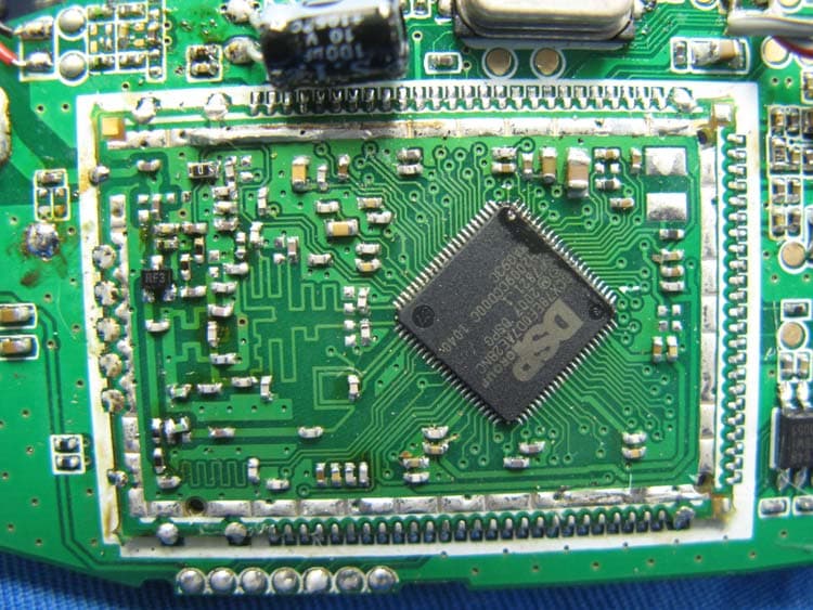
Click to zoom
Application Details
- Equipment Class
- PUB - Part 15 Unlicensed PCS Base Station
- Date of Grant
- Sep 22, 2011
- Application Purpose
- Original Equipment
- Date of Application
- Sep 22, 2011
- Equipment Note
- 1.9GHz Cordless Phone
- Frequency Range
- 1921.53600000 - 1928.44800000
- Company
- Cypress Electronics Ltd
- Country
- Hong Kong
Documents & Files
Document Text
Text extracted from the exhibit documents filed with the FCC. Open a document above to read the original.
Users Manual
Page 1 of 24 Table of Contents Important Information For your safety Important safety instructions For best performance Other information Specifications Getting Started Setting up Controls Note when setting up Initial settings Link to Cell Link to cell feature Registering a cellular phone Making/ Answering Calls Using the Handset Making cellular calls Making landline calls Answering calls Useful features during a call Registering a unit Intercom/ Locator Intercom Transferring Calls, Conference calls Handset Locator Using Caller ID service Special Programming Useful Information Troubleshooting FCC and other information Page 2 of 24 Important Information For your safety To prevent severe injury and loss of life/ property, read this section carefully before using the product to ensure proper and safe operation of your product. Power connection ¾ Use only the power source marked on the product. ¾ Do not overload power outlets and extension cords. This can result in the risk of fire or electric shock. ¾ Completely insert the AC adaptor/power plug into the power outlet. Failure to do so may cause electric shock and/or excessive heat resulting in a fire. ¾ Regularly remove any dust, etc. from the AC adaptor/power plug by pulling it from the power outlet, then wiping with a dry cloth. Accumulated dust may cause an insulation defect from moisture, etc. resulting in a fire. ¾ Unplug the product from power outlets if it emits smoke, an abnormal smell, or makes an unusual noise. These conditions can cause fire or electric shock. ¾ Unplug from power outlets and never touch the inside of the product if its casing has been broken open. ¾ Never touch the plug with wet hands. ¾ Danger of electric shock exists. Installation ¾ To prevent the risk of fire or electrical shock, do not expose the product to rain or any type of moisture. ¾ Do not place or use this product near automatically controlled devices such as automatic doors and fire alarms. Radio waves emitted from this product may cause such devices to malfunction resulting in an accident. ¾ Do not allow the AC adaptor or telephone line cord to be excessively pulled, bent or placed under heavy objects. Operating safeguards ¾ Unplug the product from power outlets before cleaning. Do not use liquid or aerosol cleaners. ¾ Do not disassemble the product. ¾ Do not spill liquids (detergents, cleansers, etc.) onto the telephone line cord plug, or allow it to become wet at all. This may cause a fire. If the telephone line cord plug becomes wet, immediately pull it from the telephone wall jack, and do not use. Medical ¾ Consult the manufacturer of any personal medical devices, such as pacemakers or hearing aids, to determine if they are adequately shielded from external RF (radio frequency) energy. (The product operates in the frequency range of 1.92 GHz to 1.93 GHz,and 2.402 GHz to 2.48 GHz ¾ Do not use the product in health care facilities if any regulations posted in the area instruct you not to do so. Hospitals or health care facilities may be using equipment that could be sensitive to external RF energy. CAUTION Installation and location ¾ Never install telephone wiring during an electrical storm. ¾ Never install telephone line jacks in wet locations unless the jack is specifically designed for wet locations. ¾ Never touch uninsulated telephone wires or terminals unless the telephone line has been disconnected at the network interface. ¾ Use caution when installing or modifying telephone lines. ¾ The AC adaptor is used as the main disconnect device. Ensure that the AC outlet is installed near the product and is easily accessible. ¾ This product is unable to make calls when: 1) the handset batteries need recharging or have failed. 2) there is a power failure. Page 3 of 24 Battery ¾ We recommend only using our provided batteries ¾ Do not open or mutilate the batteries. Released electrolyte from the batteries is corrosive and may cause burns or injury to the eyes or skin. The electrolyte is toxic and may be harmful if swallowed. ¾ Exercise care when handling the batteries. Do not allow conductive materials such as rings, bracelets, or keys to touch the batteries, otherwise a short circuit may cause the batteries and/or the conductive material to overheat and cause burns. ¾ Charge the batteries provided with or identified for use with this product only, in accordance with the instructions and limitations specified in this manual. ¾ Only use a compatible base unit to charge the batteries. Do not tamper with the base unit. ¾ Failure to follow these instructions may cause the batteries to swell or explode. Important safety instructions When using your product, basic safety precautions should always be followed to reduce the risk of fire, electric shock, and injury to persons, including the following: 1. Do not use this product near water for example, near a bathtub, washbowl, kitchen sink, or laundry tub, in a wet basement or near a swimming pool. 2. Avoid using a telephone (other than a cordless type) during an electrical storm. There may be a remote risk of electric shock from lightning. 3. Do not use the telephone to report a gas leak in the vicinity of the leak. 4. Use only the power cord and batteries indicated in this manual. Do not dispose of batteries in a fire. They may explode. 5. Check with local codes for possible special disposal instructions. CAUTION Risk of explosion if battery is replaced by an incorrect type. Dispose of used batteries according to the instructions. Use only with (Brand name: TFL, Model No: TFL30F6-400mAh-CD92-01A ; (2.4 V 400mAH) NiMH rechargeable battery) SAVE THESE INSTRUCTIONS For best performance Base unit location/avoiding noise The base unit and other compatible units use radio waves to communicate with each other. ¾ For maximum coverage and noise-free communications, place your base unit at a convenient, high, and central location with no obstructions between the handset and base unit in an indoor environment. ¾ away from…
Text truncated - open the document above for the full version.
Block Diagram
Earpiece Speaker DCX Module DCX78 (DECT RF + Base band controller) 3.2Vdc Circuit of battery charging Microphone Connector board EEPROM 128K bit Crystal 13.824MHz 2.4Vdc NiMh battery pack LCD, Mono 35x15mm Keypad 20 keys Antenna(1921.536~1928.448 MHz) Model: iRetrofone Model: iRetrofoneModel: iRetrofoneModel: iRetrofone Description: Block diagram of handset Description: Block diagram of handsetDescription: Block diagram of handsetDescription: Block diagram of handset 128K bit (1921.536~1928.448 MHz) AC/DC SMPS Ant_1 Ant_2 Input: 110~240VacOutput: 6.5Vdc PIN DCX Module (2402~2480 MHz) DCX78 (DECT RF + Base band controller) (to communicate mobile phone) Telephone charging board for iPone/iPod Regulator 5Vdc Regulator 3.2Vdc charging detect and control for handset keypad board (2 keys and 1 LED) EEPROM 16K bit Crystal 13.824M Crystal 26 MHz charging contact for handset Connector of iPhone/iPod dock Bluetooth module CSR BC417 (to communicate handset) Telephonelineinterface- Dialing- Ring detection- CID detection- Sidetone cancellation Model: iRetrofone Model: iRetrofoneModel: iRetrofoneModel: iRetrofone Description: Block diagram of base unit Description: Block diagram of base unitDescription: Block diagram of base unitDescription: Block diagram of base unit Block diagram of built-in RF transicever Block diagram of built-in RF transiceverBlock diagram of built-in RF transiceverBlock diagram of built-in RF transicever Model: iRetrofone Model: iRetrofoneModel: iRetrofoneModel: iRetrofone Description: Block diagram of Bluetooth Module Description: Block diagram of Bluetooth ModuleDescription: Block diagram of Bluetooth ModuleDescription: Block diagram of Bluetooth Module Model: iRetrofone Model: iRetrofoneModel: iRetrofone Model: iRetrofone Description: Description: Description: Description: Block diagram of DCX(DCX78) Module Block diagram of DCX(DCX78) ModuleBlock diagram of DCX(DCX78) Module Block diagram of DCX(DCX78) Module RF Block Diagram RF Block DiagramRF Block Diagram RF Block Diagram Synthesizer Block Diagram Synthesizer Block DiagramSynthesizer Block Diagram Synthesizer Block Diagram Frequency Plan: Frequency Plan:Frequency Plan: Frequency Plan: RF Channel TX/RX frequency (MHz) VCO frequency (MHz) 01928.448 2892.672 11926.72 2890.08 21924.992 2887.448 31923.264 2884.896 41921.536 2882.304 Model: iRetrofone Model: iRetrofoneModel: iRetrofone Model: iRetrofone Description: RF Description: RF Description: RF Description: RF Block diagram of DCX Module Block diagram of DCX ModuleBlock diagram of DCX Module Block diagram of DCX Module
ID Label/Location Info
27x5.5 27x5.5 SIZE: 59.5x40 MM SIZE: 59.5x48.5 MM : Factory code : Year : The day of year (11 for 2011) (1st of Jan is 001, 2nd of Dec is 336) SN: 000001 SN: 000001 UNYYDDD SN: 000001 UNYYDDD YY DDD Example : 000001-100000 NNNNNN SIZE:15X10MM SIZE:22X12MM Y5PIRBD10US001 2.4V DC 400mAh 50541241 iRetrofone Y5PIRBD10US001 2.4V DC 400mAh 50541241 iRetrofone 50541241 Y5PIRBD10US001 6.5V1500mA Class 2 xxxx xxxxxxxx Imported by Polyconcept iRetrofone xxxxxx 1.5mm 1.0mm 2.1mm 2.15mm 3.0mm xxxxxx HAC HAC CM ”, Height 1.0mm minimum US”, Height 2.0mm minimum 50541241 Y5PIRBD10US001 6.5V1500mA Class 2 xxxx xxxxxxxx Imported by Polyconcept iRetrofone xxxxxx HAC
Internal Photos
INTERTEK TESTING SERVICES Internal photos FCC ID: Y5PIRBD10US001 internal photos - 1 of 11 Base Unit assembly Base Unit Main PCB comp side INTERTEK TESTING SERVICES Internal photos FCC ID: Y5PIRBD10US001 internal photos - 2 of 11 Base Unit Main PCB solder side Base Unit Page Key front side INTERTEK TESTING SERVICES Internal photos FCC ID: Y5PIRBD10US001 internal photos - 3 of 11 Base Unit Page Key rear side Base Unit Oscillator PCB comp side (View 1) INTERTEK TESTING SERVICES Internal photos FCC ID: Y5PIRBD10US001 internal photos - 4 of 11 Base Unit Oscillator PCB comp side (View 2) Base Unit Oscillator front side INTERTEK TESTING SERVICES Internal photos FCC ID: Y5PIRBD10US001 internal photos - 5 of 11 Base Unit Oscillator rear side Base Unit Bluetooth Module front side INTERTEK TESTING SERVICES Internal photos FCC ID: Y5PIRBD10US001 internal photos - 6 of 11 Base Unit Bluetooth Module rear side INTERTEK TESTING SERVICES Internal photos FCC ID: Y5PIRBD10US001 internal photos - 7 of 11 Handset assembly Handset Main PCB comp side (View 1) INTERTEK TESTING SERVICES Internal photos FCC ID: Y5PIRBD10US001 internal photos - 8 of 11 Handset Main PCB comp side (View 2) Handset Main PCB comp side (View 3) INTERTEK TESTING SERVICES Internal photos FCC ID: Y5PIRBD10US001 internal photos - 9 of 11 Handset Main PCB display side (View 1) Handset Main PCB display side (View 2) INTERTEK TESTING SERVICES Internal photos FCC ID: Y5PIRBD10US001 internal photos - 10 of 11 Handset Oscillator PCB comp side (view 1) Handset Oscillator PCB comp side (view 2) INTERTEK TESTING SERVICES Internal photos FCC ID: Y5PIRBD10US001 internal photos - 11 of 11 Handset Oscillator front side Handset Oscillator front side
Operational Description
Technical Description of iRetrofone 1. BASE UNIT Base unit could access telephone line (PSTN) or Bluetooth linking (mobile phone). It communicates the cordless handset through DECT RF system. Thus, a user could use the cordless handset to make phone call with PSTN or mobile phone (through Bluetooth connection to the base unit). Beside phone call, base unit serves as charging dock for iPhone or iPod products 1.1 Main controller DCX78 is an integrated chip for DECT cordless phone from DSPG. It composed of MCU, DSP, RF transceiver and RF PA. It is an ARM based device which works with 13.824MHz crystal with on-chip tuning capability. It has on-chip 1MB Flash and 64KB RAM. 1.2 User interface Keypad Buttons Operations Descriptions PAGE Press once When the base is in idle state, the base will page all registered DECT handsets. When the base is in paging mode, the base will stop paging. BT Press once Initiate BT connection to the existing paired mobile(s). LED Functions LED – Red LED – Green Remarks DECT Registration mode (press & hold PAGE key for 10s) 200ms On/Off N/A 2 minutes Sync with the other LED if the cell phone is also pairing mode Cell phone Pairing mode N/A 200ms On/Off 2 minutes Sync with the other LED if DECT is also in registration mode Charge On N/A - PSTN In Use 500ms On/Off N/A Sync with the other LED if the cell phone is also in use Cell In Use N/A 500ms On/Off Sync with the other LED if the PSTN is also in use Paging 640ms On/ 1920ms Off N/A 1 minute PSTN Ringing 50ms On/Off N/A Sync with the other LED if the cell phone is also ringing Cell phone Ringing N/A 50ms On/Off If the base is already connected to some cell phone (talk or ringing), the ringing of the other cell phone will be ignored. Sync with the other LED if the PSTN is also ringing. 1.3 Power Management Power management includes generation of 2 regulated DC supplies: 3.2V and 5V from the adaptor 6.5VDC. The 5V DC is regulated by U2 which serves only battery charging for iPhone or iPod products. The 3.2V DC is regulated by U1 which supply the operation of base unit. 1.4 External Memory There is one external memory: U3 (16KBit EEPROM). The EEPROM is for storing system parameters and call logs. 1.5 Telephone line Interface The line interface circuit provides the following functions: i.) Hook switch : Q6,7,12 perform the hook switch function ii.) Line receive, transmit, sidetone cancellation are controlled by the circuit about Q2, Q3 & Q17 iii.) Ringer detection: Ringing signal is tapped through C104 and converted to logic by Q8 iv.) Line DC detection : The resistor network R16,58 feed the on-hook line DC level to the controller v.) CID FSK detection: The on-hook FSK detection is done by the network C36 and 37. This couple the signal to CODEC input of controller for FSK decoding. 1.6 Charging Circuit and Detection Charging current is defined by R50 and D11. The detection is generated by Q15 and feed to the controller. 1.7 Bluetooth module The Bluetooth module is used for base unit to communicate with external mobile phone. The main chip is CSR 417 by CSR. The operation is under specification of Bluetooth 2.1+EDR with profile HFP 1.5. 1.8 BLOCK DIAGRAM 2. Handset Handset could work with the base unit through RF of DECT standard. It is able to make phone call through PSTN or BT device attached to the base unit. 2.1 Baseband Controller DCX78 is an integrated chip for DECT cordless phone from DSPG. It composed of MCU, DSP, RF transceiver and RF PA. It is an ARM based device which works with 13.824MHz crystal with on-chip tuning capability. It has on-chip 1MB Flash and 64KB RAM. 2.2 User interface Keypad: Using on-chip triangular scanning keypad, it provides 20 keys. Display: The display is a 35x15mm, mono colour LCD. It is controlled by the controller through the data bus. 2.3 Power Management The handset unit could work with a battery of 2.4Vdc. Battery level and power failure detection is done by the resistor network R46 & 47, feeding signal to the A/D of controller. The controller could generate 3.2Vdc with voltage-doubler of itself. The 3.2Vdc is used for LED backlight and EEPROM IC. 2.4 External Memory The system contains one external EEPROM of size 128KBit, which stores system data as well as phonebook and redial buffers. 2.5 Charge Control and Cradle-detection The charging control is done by Q5, Q6 & Q8. The controller can switch on/off the charging current through Q8 while current limitation is defined by R9. Note that R83 is to provide over-current protection for safety. Cradle detection is done by R11 & R12. Hence one MCU’ s I/O is working as input and output to perform charging control and cradle-detection functions. 2.6 Block Diagram 3. DECT RF between Handset and Base Unit The same RF part is embedded on DCX78 chip in both handset and base. It is including a transceiver and a power amplifier. The transceiver handles all the DECT RF transmit and receive. The power amplifier increase the transmit power to increase the range of the system. * Only layout is different for handset RF and base RF 3.1 Transmit chain As the output frequency of the synthesizer is determined by adjusting the digital control stream to the dual modulus divider, it is relatively simple to frequency modulate the PLL. A digital word (proportional to the desired instantaneous amplitude of the TX modulation data) is simply summed with the digital control stream output of the Δ -Σ modulator. This causes the output frequency to increase or decrease proportional to the digital word. The digital modulation word is not held constant across the duration of a bit applied to the TR_DATA input, but rather is stepped in a sequence that synthesizes a Gaussian-filtered (BT=0.5, 0.6, 0.7) version of the input data stream. Thus the TR_DATA input data stream is not actually digitally filtered, but instead the edge transitions on the TR_DATA input pin are used to synchronously recall a digitally synthesized waveform from an internal lookup table. The signal at…
Text truncated - open the document above for the full version.
RF Exposure Info
INTERTEK TESTING SERVICES FCC ID:Y5PIRBD10US001 RF exposure info - 1 of 1 For Maximum Permissible Exposure (MPE) evaluation of the base unit, the maximum power density at 20 cm from this mobile transmitter shall be less than the General Population / Uncontrolled MPE limit in OET Bulletin 65. For the base unit of tested model of 50541241, the maximum field strength measured (FS) was 114.3 dBμV/m. The distance (D) between the antenna and the equipment under test (EUT) was 3 meters. And the maximum source-based time- averaging duty factor in two-handsets operation is 12.5%. From these data, the exposed power density at a distance (R) of 20cm from the center of radiation of the antenna can be calculated according to OET Bulletin 65 as follow: The radiated power (EIRP) = (FS*D) 2 / 30 = 80.75 mW The radiated (EIRP) source-based time-averaging output power = (80.75 * 0.125) mW = 10.09 mW The power density at 20 cm from the antenna = EIRP / 4πR 2 = 0.0020 mW cm -2 In the frequency range of 1,500 - 100,000MHz, the MPE limit is 1.0 mWcm -2 for general population and uncontrolled exposure. As the measured power density at 20cm from the transmitter is lower than the MPE limit, the compliance to the MPE limit can be ensured by indicating the minimum 20cm separation between the transmitter's radiating structures and body of the user or nearby persons. The following RF exposure statement is proposed to be included in the user manual: “ FCC RF Radiation Exposure Statement Caution: To maintain compliance with the FCC’s RF exposure guidelines, place the base unit at least 20cm from nearby persons.”
Schematics
Cypress Electronics Ltd. iRetrofone BS key board Jack Tsui B 11 REV: SIZE: CODE: DRAWN: DATED: DATED: CHECKED:QUALITY CONTROL: DATED: DATED: RELEASED: COMPANY:TITLE: DRAWING NO: SHEET: OF SCALE: REVISION RECORD APPROVED: ECO NO: ABD DATE: 1 2 3 4 5 6 DCAB C LTR 1234567 PAGE BT LED 12 12 TO_CHG_CONTACT CH+ CH- LED1LED2 GND iPhone Charge board Cypress Electronics Ltd. B 11 REV: SIZE: CODE: DRAWN: DATED: DATED: CHECKED:QUALITY CONTROL: DATED: DATED: RELEASED: COMPANY:TITLE: DRAWING NO: SHEET: OF SCALE: REVISION RECORD APPROVED: ECO NO: ABD DATE: 1 2 3 4 5 6 DCAB C LTR 14 USBD+ 6 USBD- 8 USB-VBUS 10111215 GND 2030 CON401 12 CON301 R4 R34R35 R36 1234 SW1 1234 SW2 EDY!npevmf`S1c`CT/tdi.2!.!Uvf!Kvo!25!21;41;22!3122 EDY!npevmf`S1c`CT/tdi.3!.!Uvf!Kvo!25!21;41;24!3122 HS connector board Cypress Electronics Ltd. B 11 REV: SIZE: CODE: DRAWN: DATED: DATED: CHECKED:QUALITY CONTROL: DATED: DATED: RELEASED: COMPANY:TITLE: DRAWING NO: SHEET: OF SCALE: REVISION RECORD APPROVED: ECO NO: ABD DATE: 1 2 3 4 5 6 DCAB C LTR 1234567 JP1 1 2 JP2 1 2 JP3 SCL SDA BAT+ GND SCL MIC+MIC- SDA BAT+ EDY!npevmf`S1c`IT/tdi.2!.!Uvf!Kvo!25!21;44;4:!3122 EDY!npevmf`S1c`IT/tdi.3!.!Uvf!Kvo!25!21;44;51!3122
Test Report
INTERTEK TESTING SERVICES 26dB Emission Bandwidth Plots FCC ID: Y5PIRBD10US001 26bw - 1 of 2 A0 Base unit, Lowest channel, Traffic carrier Base unit, Highest channel, Traffic carrier INTERTEK TESTING SERVICES 26dB Emission Bandwidth Plots FCC ID: Y5PIRBD10US001 26bw - 2 of 2 A0 Handset unit, Lowest channel, Traffic carrier Handset unit, Highest channel, Traffic carrier
Test Report
Report no.: HK11051691-1 Standby +Charging (Handset + IPod) Mode AC Mains Ctrl No.: N/A 6DB AC 150 kHz30 MHz dBμV dBμV 1 PK CLRWR 2 AV CLRWR SGL TDS RBW 9 kHz MT 1 s PREAMP OFFAtt 10 dB AUTO 1 MHz10 MHz 0 10 20 30 40 50 60 70 80 90 100 CF15MAV CF15MQP Date: 16.JUN.2011 19:11:47 Report no.: HK11051691-1 Standby +Charging (Handset + IPod) Mode AC Mains Ctrl No.: N/A EDIT PEAK LIST (Final Measurement Results) Trace1: CF15MQP Trace2: CF15MAV Trace3: --- TRACE FREQUENCY LEVEL dBμV DELTA LIMIT dB 2 CISPR Average154.5 kHz 33.35 L1 -22.39 2 CISPR Average285 kHz 42.25 L1 -8.41 1 Quasi Peak 285 kHz 48.23 L1 -12.43 1 Quasi Peak 307.5 kHz 51.87 L1 -8.16 2 CISPR Average312 kHz 44.01 L1 -5.90 1 Quasi Peak 546 kHz 41.29 L1 -14.70 2 CISPR Average564 kHz 35.28 L1 -10.71 1 Quasi Peak 591 kHz 42.26 L1 -13.73 2 CISPR Average627 kHz 36.33 L1 -9.66 1 Quasi Peak 978 kHz 41.42 L1 -14.57 2 CISPR Average1.0005 MHz 35.31 L1 -10.68 2 CISPR Average1.311 MHz 32.50 L1 -13.49 1 Quasi Peak 1.4415 MHz 41.62 L1 -14.37 1 Quasi Peak 1.6305 MHz 40.48 L1 -15.51 2 CISPR Average1.824 MHz 34.89 L1 -11.10 2 CISPR Average2.634 MHz 34.51 L1 -11.48 1 Quasi Peak 2.706 MHz 40.95 L1 -15.04 1 Quasi Peak 2.9895 MHz 39.71 L1 -16.28 2 CISPR Average3.0435 MHz 33.74 L1 -12.25 2 CISPR Average4.8525 MHz 31.89 L1 -14.10 Date: 16.JUN.2011 19:11:28 Report no.: HK11051691-1 Standby +Charging (Handset + IPod) Mode AC Mains Ctrl No.: N/A EDIT PEAK LIST (Final Measurement Results) Trace1: CF15MQP Trace2: CF15MAV Trace3: --- TRACE FREQUENCY LEVEL dBμV DELTA LIMIT dB 1 Quasi Peak 4.857 MHz 38.25 L1 -17.74 1 Quasi Peak 6.792 MHz 47.09 L1 -12.90 2 CISPR Average7.008 MHz 40.36 L1 -9.63 Date: 16.JUN.2011 19:11:39 Report no.: HK11051691-1 Ringing +Charging (Handset + IPod) Mode AC Mains Ctrl No.: N/A 6DB AC 150 kHz30 MHz dBμV dBμV 1 PK CLRWR 2 AV CLRWR SGL TDS RBW 9 kHz MT 1 s PREAMP OFFAtt 10 dB AUTO 1 MHz10 MHz 0 10 20 30 40 50 60 70 80 90 100 CF15MAV CF15MQP Date: 16.JUN.2011 19:06:08 Report no.: HK11051691-1 Ringing +Charging (Handset + IPod) Mode AC Mains Ctrl No.: N/A EDIT PEAK LIST (Final Measurement Results) Trace1: CF15MQP Trace2: CF15MAV Trace3: --- TRACE FREQUENCY LEVEL dBμV DELTA LIMIT dB 2 CISPR Average285 kHz 41.02 L1 -9.64 1 Quasi Peak 289.5 kHz 49.51 L1 -11.02 2 CISPR Average312 kHz 46.24 L1 -3.66 1 Quasi Peak 312 kHz 52.82 L1 -7.09 1 Quasi Peak 523.5 kHz 42.24 L1 -13.75 2 CISPR Average550.5 kHz 34.86 L1 -11.13 2 CISPR Average586.5 kHz 35.84 L1 -10.16 1 Quasi Peak 649.5 kHz 42.89 L1 -13.10 1 Quasi Peak 874.5 kHz 40.72 L1 -15.28 2 CISPR Average1.0365 MHz 35.31 L1 -10.68 1 Quasi Peak 1.2795 MHz 40.81 L1 -15.18 2 CISPR Average1.473 MHz 35.30 L1 -10.69 1 Quasi Peak 1.617 MHz 40.65 L1 -15.34 2 CISPR Average1.9005 MHz 35.61 L1 -10.38 1 Quasi Peak 2.2965 MHz 41.15 L1 -14.84 2 CISPR Average2.328 MHz 35.50 L1 -10.49 1 Quasi Peak 2.9805 MHz 40.21 L1 -15.78 2 CISPR Average3.111 MHz 33.38 L1 -12.61 2 CISPR Average4.7085 MHz 32.46 L1 -13.53 1 Quasi Peak 4.884 MHz 38.38 L1 -17.62 Date: 16.JUN.2011 19:05:51 Report no.: HK11051691-1 Ringing +Charging (Handset + IPod) Mode AC Mains Ctrl No.: N/A EDIT PEAK LIST (Final Measurement Results) Trace1: CF15MQP Trace2: CF15MAV Trace3: --- TRACE FREQUENCY LEVEL dBμV DELTA LIMIT dB 1 Quasi Peak 6.855 MHz 47.86 L1 -12.13 2 CISPR Average6.963 MHz 40.86 L1 -9.13 Date: 16.JUN.2011 19:06:01 Report no.: HK11051691-1 Talk +Charging (IPod) Mode AC Mains Ctrl No.: N/A 6DB AC 150 kHz30 MHz dBμV dBμV 1 PK CLRWR 2 AV CLRWR SGL TDS RBW 9 kHz MT 1 s PREAMP OFFAtt 10 dB AUTO 1 MHz10 MHz 0 10 20 30 40 50 60 70 80 90 100 CF15MAV CF15MQP Date: 16.JUN.2011 19:25:14 Report no.: HK11051691-1 Talk +Charging (IPod) Mode AC Mains Ctrl No.: N/A EDIT PEAK LIST (Final Measurement Results) Trace1: CF15MQP Trace2: CF15MAV Trace3: --- TRACE FREQUENCY LEVEL dBμV DELTA LIMIT dB 1 Quasi Peak 172.5 kHz 40.21 L1 -24.62 2 CISPR Average289.5 kHz 40.51 L1 -10.02 1 Quasi Peak 289.5 kHz 48.13 L1 -12.40 2 CISPR Average312 kHz 45.20 L1 -4.70 1 Quasi Peak 312 kHz 52.65 L1 -7.26 1 Quasi Peak 501 kHz 41.30 L1 -14.69 2 CISPR Average564 kHz 33.99 L1 -12.00 1 Quasi Peak 568.5 kHz 40.71 L1 -15.29 2 CISPR Average685.5 kHz 34.76 L1 -11.23 1 Quasi Peak 847.5 kHz 40.86 L1 -15.13 2 CISPR Average1.059 MHz 34.47 L1 -11.52 2 CISPR Average1.1265 MHz 34.61 L1 -11.38 1 Quasi Peak 1.149 MHz 40.52 L1 -15.47 1 Quasi Peak 1.851 MHz 39.77 L1 -16.22 2 CISPR Average2.031 MHz 34.06 L1 -11.93 2 CISPR Average2.3775 MHz 33.44 L1 -12.55 1 Quasi Peak 2.436 MHz 40.47 L1 -15.52 2 CISPR Average3.066 MHz 32.35 L1 -13.64 1 Quasi Peak 3.309 MHz 38.99 L1 -17.00 2 CISPR Average4.767 MHz 31.83 L1 -14.16 Date: 16.JUN.2011 19:24:56 Report no.: HK11051691-1 Talk +Charging (IPod) Mode AC Mains Ctrl No.: N/A EDIT PEAK LIST (Final Measurement Results) Trace1: CF15MQP Trace2: CF15MAV Trace3: --- TRACE FREQUENCY LEVEL dBμV DELTA LIMIT dB 1 Quasi Peak 4.8345 MHz 38.67 L1 -17.32 2 CISPR Average6.927 MHz 39.66 L1 -10.33 1 Quasi Peak 7.0395 MHz 46.50 L1 -13.49 Date: 16.JUN.2011 19:25:06
Test Report
INTERTEK TESTING SERVICES Unwanted Emission Inside The Sub-Band Plots FCC ID: Y5PIRBD10US001 inband - 1 of 2 A0 Base unit, Lowest channel, Traffic carrier Base unit, Highest channel, Traffic carrier INTERTEK TESTING SERVICES Unwanted Emission Inside The Sub-Band Plots FCC ID: Y5PIRBD10US001 inband - 2 of 2 A0 Handset unit, Lowest channel, Traffic carrier Handset unit, Highest channel, Traffic carrier
Test Report
INTERTEK TESTING SERVICES Peak Transmit Power Plots FCC ID: Y5PIRBD10US001 peaktp - 1 of 2 A0 Base unit, Lowest channel, Traffic carrier Base unit, Highest channel, Traffic carrier INTERTEK TESTING SERVICES Peak Transmit Power Plots FCC ID: Y5PIRBD10US001 peaktp - 2 of 2 A0 Handset unit, Lowest channel, Traffic carrier Handset unit, Highest channel, Traffic carrier
Test Report
INTERTEK TESTING SERVICES Power Spectral Density Plots FCC ID: Y5PIRBD10US001 psd - 1 of 2 A0 Base unit, Lowest channel, Traffic carrier Base unit, Highest channel, Traffic carrier INTERTEK TESTING SERVICES Power Spectral Density Plots FCC ID: Y5PIRBD10US001 psd - 2 of 2 A0 Handset unit, Lowest channel, Traffic carrier Handset unit, Highest channel, Traffic carrier
Test Report
- The test report only allows to be revised within the retention period unless further standard or the requirement was noticed. - This report is for the exclusive use of Intertek's Client and is provided pursuant to the agreement between Intertek and its Client. Intertek's responsibility and liability are limited to the terms and conditions of the agreement. Intertek assumes no liability to any party, other than to the Client in accordance with the agreement, for any loss, expense or damage occasioned by the use of this report. Only the Client is authorized to permit copying or distribution of this report and then only in its entirety. Any use of the Intertek name or one of its marks for the sale or advertisement of the tested material, product or service must first be approved in writing by Intertek. The observations and test results in this report are relevant only to the sample tested. This report by itself does not imply that the material, product, or service is or has ever been under an Intertek certification program. Intertek Testing Services Hong Kong Ltd. 2/F., Garment Centre, 576 Castle Peak Road, Kowloon, Hong Kong. Tel: (852) 2173 8888 Fax: (852) 2785 5487 Website: www.hk.intertek-etlsemko.com Cypress Electronics Ltd Application For 47 CFR Part 15: 2009 Certification Unlicensed Personal Communication Service Devices FCC ID: Y5PIRBD10US001 Model: 50541241, 50541247, 50541248 Test Report Number: HK11051691-1 Issue Date: August 15, 2011 MN/ cl INTERTEK TESTING SERVICES Test Report Number: HK11051691-1 Page 1 of 57 FCC ID: Y5PIRBD10US001 Table of Contents 1.0 Summary of Test Results........................................................................................ 4 2.0 General Description................................................................................................. 7 2.1 Product Description ................................................................................................. 7 2.2 Technical Description .............................................................................................. 7 2.3 Test Methodology.................................................................................................... 8 2.4 Test Facility............................................................................................................. 8 3.0 System Test Configuration.................................................................................... 10 3.1 Justification ........................................................................................................... 10 3.2 Conducted Emission Test Configuration ................................................................ 11 3.3 Conducted Monitoring and Operational Test Configuration.................................... 11 3.4 EUT Exercising Software....................................................................................... 11 3.5 Details of EUT and Description of Peripherals....................................................... 12 3.6 Measurement Uncertainty ..................................................................................... 12 4.0 Measurement Results............................................................................................ 14 4.1 Antenna Requirement........................................................................................... 14 4.2 Digital Modulation Techniques............................................................................... 14 4.3 Emission Bandwidth.............................................................................................. 15 4.4 Directional Gain of the Antenna ............................................................................. 15 4.5 Peak Transmit Power .......................................................…
Text truncated - open the document above for the full version.
Contact Information
Applicant
James Cheng(Manager)
Technical Contact
Intertek Testing Services Hong Kong LtdMelvin Nip
[email protected]2173-8888
Flat D, 5/F Garment Centre · Kowloon · Hong Kong
Non-Technical Contact
Intertek Testing Services Hong Kong LtdMelvin Nip
[email protected]2173 8888
Test Firm
Intertek Testing Services Hong Kong Ltd.Billy Chow
Technical Specifications
| # | Rule Parts | Frequency Range | Power Output |
|---|---|---|---|
| 1 | 15D | 1.92 GHz - 1.93 GHz | 44.00 mW |