Y6OMDXRADIO-CL2Zigbee Module Radio
Franklin Electric Inc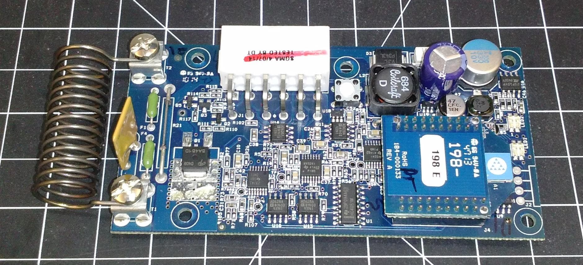
Click to zoom
Application Details
- Equipment Class
- DXX - Part 15 Low Power Communication Device Transmitter
- Date of Grant
- Sep 30, 2014
- Application Purpose
- Original Equipment
- Date of Application
- Sep 30, 2014
- Equipment Note
- Zigbee Module Radio
- Frequency Range
- 2410.00000000 - 2465.00000000
- Company
- Franklin Electric Inc
- Country
- United States
Documents & Files
Document Text
Text extracted from the exhibit documents filed with the FCC. Open a document above to read the original.
Users Manual
Doc No: TBD Page 1 The information contained herein is the confidential and proprietary property of Midtronics, Inc. User’s Manual MDX ZIGBEE RADIO Revision: 1 Date: 08/12/14 Doc No: TBD Page 2 The information contained herein is the confidential and proprietary property of Midtronics, Inc. Table of Contents Table of Contents ........................................................................................................................................................... 2 1. Summary ................................................................................................................................................................ 3 2. MDX ZIGBEE RADIO Installation ................................................................................................................... 4 3. Technical Specifications of MDX ZIGBEE RADIO Module .................................................................... 4 3.1 Description of MDX ZIGBEE RADIO module ...................................................................................... 4 3.2 MDX ZIGBEE RADIO Module Specifications Table .......................................................................... 6 3.3 Table of Allowable Channels .................................................................................................................... 6 3.4 MDX ZIGBEE RADIO Module Antenna Specifications Table ........................................................ 6 4. Agency Certifications for MDX ZIGBEE RADIO ........................................................................................ 7 5. Battery Sensor Installation .............................................................................................................................. 7 6. Intended Use ......................................................................................................................................................... 8 7. Safety ........................................................................................................................................................................ 9 8. Patents .................................................................................................................................................................. 10 9. Limited Warranty ............................................................................................................................................. 10 10. Service .................................................................................................................................................................. 10 Reference Documents Document Title Revision Document Maintenance Contact Document Location CGFS-W-201 Rev4 Gen 2 Dual Sensor Wiring Instructions 4 Brad Walker Global Field Service Manager office.630.321.8006 [email protected] Midtronics internal document for training approved installers. Available upon Request Doc No: TBD Page 3 The information contained herein is the confidential and proprietary property of Midtronics, Inc. 1. Summary • The MDX ZIGBEE RADIO is installed onto the CELLGUARD Battery Sensor during manufacturing of the sensor by Midtronics Inc. The MDX ZIGBEE RADIO module is inside the product enclosure, and is not accessible by the end user. • The configuration and settings of the MDX ZIGBEE RADIO module are preprogrammed during manufacturing by Midtronics Inc and are not accessible to the end user • CELLGUARD Battery Sensor containing the internal MDX ZIGBEE RADIO module is not installed by the end user. The CELLGUARD Battery Sensor shall only be installed by installers trained and certified by Midtronics Inc with explicit approval by Midtronics Inc. • The MDX ZIGBEE RADIO module is only installed only in the products listed in the table below. MDX ZIGBEE RADIO module is installed only in the CELLGUARD Battery Sensors in this Table Sensor Part Number Description PCBA Part Number CGDS-02V PCBA, CELLGUARD DUAL 2V SENSOR GEN II + 198-000315 CGDS-04V PCBA, CELLGUARD DUAL 04V SENSOR GEN II + 198-000316 CGDS-12V PCBA, CELLGUARD DUAL 12V SENSOR GEN II + 198-000314 CGDS-16V PCBA, CELLGUARD DUAL 16V SENSOR GEN II + TBD CGSS-02V PCBA, CELLGUARD SINGLE 2V SENSOR GEN II + TBD CGSS-12V PCBA, CELLGUARD SINGLE 12V SENSOR GEN II + TBD CGDH-02V PCBA, CELLGUARD DUAL HYBRID 2V SENSOR GEN II + 198-000336 CGDH-04V PCBA, CELLGUARD DUAL HYBRID 4V SENSOR GEN II + 198-000335 CGDH-06V PCBA, CELLGUARD DUAL HYBRID 6V SENSOR GEN II + 198-000334 CGDH-08V PCBA, CELLGUARD DUAL HYBRID 8V SENSOR GEN II + 198-000333 CGDH-12V PCBA, CELLGUARD DUAL HYBRID 12V SENSOR GEN II + 198-000332 CGDH-16V PCBA, CELLGUARD DUAL HYBRID 16V SENSOR GEN II + 198-000331 GEN II CELLGUARD Battery Sensor, Model: CGDS-12V Doc No: TBD Page 4 The information contained herein is the confidential and proprietary property of Midtronics, Inc. 2. MDX ZIGBEE RADIO Installation The MDX ZIGBEE RADIO module inside the CELLGUARD Battery Sensor shall not be accessed by the end user. The radio module shall not be removed or installed. The radio module requires no setup, configuring, or maintenance by the end user. The radio module inside the CELLGUARD Battery Sensor should be invisible to the end user. 3. Technical Specifications of MDX ZIGBEE RADIO Module 3.1 Description of MDX ZIGBEE RADIO module The MDX ZIGBEE RADIO module is located on the PCB assembly of the Dual Sensor, and enclosed in the CELLGUARD Battery Sensor case. The radio module is not accessible by the user. MDX ZIGBEE RADIO Module Doc No: TBD Page 5 The information contained herein is the confidential and proprietary property of Midtronics, Inc. MDX ZIGBEE RADIO Module MDX ZIGBEE RADIO Installed on PCBA CELLGUARD Battery Sensor PCBA Inside Enclosure Doc No: TBD Page 6 The information contained herein is the confidential and proprietary property of Midtronics, Inc. 3.2 MDX ZIGBEE RADIO Module Specifications Table Radio Specifications Data Rate 250kbps Supply Voltage (Supplied by Dual Sensor) 3.3…
Text truncated - open the document above for the full version.
Cover Letter(s)
Page 1 of 1 RP-7XXXL 12 East Devonwood SOLVING A WAVE OF EMI COMPLIANCE PROBLEMS Romeoville, IL 60446 ENTER August 21, 2014 Tel: (815) 293-0772 Page 1 of 1 Fax: (815) 293-0820 Federal Communications Commission Authorization and Evaluation Division 7435 Oakland Mills Rd. Columbia, MD 21046 Industry Canada Certification and Engineering Bureau Ottawa, Ontario K2H 8S2 Canada Reference FCC ID: Y60MDXRADIO-CL2 Reference IC ID: 9453A-MDXRADIO Organization: Midtronics, Inc. 7000 Monroe St. Willowbrook, IL 60527 1. 2. Long Term Confidentiality Midtronics requests that the following materials be withheld from public inspection permanently under 47 C.F.R. 0.457 & 0.459: (1) Detailed Circuit Schematics of the EUT (2) Block Diagrams (3) EUT Description The above materials contain proprietary and confidential information not customarily released to the public. The public disclosure of these materials provides unjustified benefits to its competitors in the market. They are considered confidential trade secrets Authorized Signature Joseph Strzelecki Senior EMC Engineer Radiometrics Midwest Corporation Authorized Agent for Midtronics.
Cover Letter(s)
Page 1 of 2 RP-7899 12 East Devonwood SOLVING A WAVE OF EMI COMPLIANCE PROBLEMS Romeoville, IL 60446 Tel: (815) 293-0772 Fax: (815) 293-0820 Federal Communications Commission Authorization and Evaluation Division REFERENCE Industry Canada ID: 9453A-MDXRADIO FCC ID: Y60MDXRADIO-CL2 RE: Request for Limited Single-modular transmitter APPLICANT: Midtronics. This module will only be used by Midtronics. It will not be sold as a separate product to individuals or companies. Therefore, Midtronics will fully control the use and installation procedures. It will be used with Cell Guard battery sensors. The label provided in the exhibit is the final label. This is the only type of enclosure that this module will be used for. It will be fully controlled by Midtronics. Midtronics is placing the module in hosts that are very similar to the one it was tested with. Midtronics is controlling the use of the module and will make sure the Label is placed on the outside of all host systems. The product will always be inside another enclosure during actual use. The end user will not have ready access to the module. FCC Items are 1 to 8. Canada Requirements are (a) to (h). Item Requirement Meets Justification 1 The radio elements of the modular transmitter must have their own shielding. The physical crystal and tuning capacitors may be located external to the shielded radio elements. No The Base board is multi layered with an inner ground shield. In addition there is a top positioned printed circuit board shield that is connected to circuit ground. The module does not depend on any other shield. (a) The radio elements must have the radio frequency circuitry must be shielded. Physical/discrete and tuning capacitors may be located external to the shield, but must be on the module assembly. 2 The modular transmitter must have buffered modulation/data inputs (if such inputs are provided) to ensure that the module will comply with part 15 requirements under conditions of excessive data rates or over-modulation. Yes There are no buffered RF components. The radio transceiver is fully integrated and connected to the antenna element through passive components. (b) The module shall have buffered modulation/data input(s) (if such inputs are provided) to ensure that the module will comply with the requirements set out in the applicable RSS standard under conditions of excessive data rates or over- modulation. 3 The modular transmitter must have its own power supply regulation. Yes An external 3.3V regulated supply is filtered through the module’s LC (inductor/capacitor) circuit to further reduce high frequency components from and to the main printed circuit board. (c) The module shall have its own power supply regulation on the module. This is to ensure that the module will comply with the requirements set out in the applicable standard regardless of the design of the power supplying circuitry in the host device which houses the module. 4 The modular transmitter must comply with the antenna and transmission system requirements of §§ 15.203, 15.204(b) and 15.204(c). The antenna must either be permanently attached or employ a “unique” antenna coupler (at all connections between the module and the antenna, including the cable). The “professional installation” provision of § 15.203 is not applicable to modules but can apply to limited modular approvals under paragraph (b) of this section. Yes The antenna is soldered on to the printed circuit board and cannot be changed by the end user. No other antennas are used with the module. Page 2 of 2 RP-7899 Item Requirement Meets Justification (d) The module shall comply with the provisions for external power amplifiers and antennas detailed in this standard. The equipment certification submission shall contain a detailed description of the configuration of all antennas that will be used with the module. 5 The modular transmitter must be tested in a stand-alone configuration, i.e. the module must not be inside another device during testing for compliance with part 15 requirements. Unless the transmitter module will be battery powered, it must comply with the AC line conducted requirements found in §15.207. AC or DC power lines and data input/output lines connected to the module must not contain ferrites, unless they will be marketed with the module (see §15.27(a)). The length of these lines shall be the length typical of actual use or, if that length is unknown, at least 10 cm to insure that there is no coupling between the case of the module and supporting equipment. Any accessories, peripherals, or support equipment connected to the module during testing shall be unmodified and commercially available (see §15.31(i)). Yes The EUT was tested connected to a battery sensor, as in its normal installation. The installations are controlled by Midtronics. The EUT was tested with an external battery. No Conducted emissions are required since it will always be battery powered. The module was installed on the top of a PCB with no shielding around it. The system has a totally non- conductive plastic housing. The EUT had no additional shielding. (e) The module shall be tested for compliance with the applicable standard in a stand-alone configuration, i.e. the module must not be inside another device during testing. 6 The modular transmitter must be equipped with either a permanently affixed label or must be capable of electronically displaying its FCC identification number. Yes The FCC ID label format is included in the filing. The product will always be inside another enclosure during actual use. The outside of the device in which the module is installed will display a label referring to the enclosed module. Midtronics is controlling the use of the module and will make sure the Label is placed on the outside of all host systems. (f) The module shall comply with the Category I equipment labeling requirements. 7 The modular transmitter must comply with any specific rules or operating requirements …
Text truncated - open the document above for the full version.
External Photos
Authorized Agent: Radiometrics Midwest Corporation (815) 293-0772 Internal EUT Photographs Board with Shield Photograph of Radio Board: Foil Side Authorized Agent: Radiometrics Midwest Corporation (815) 293-0772 Photograph of Radio Board: Component Side Photograph of host Sensor Board with Module: Component Side Authorized Agent: Radiometrics Midwest Corporation (815) 293-0772 Photograph of Host Sensor Board: Component Side, Module shield removed Photograph of Sensor Board: Component Side, Radio Board removed Authorized Agent: Radiometrics Midwest Corporation (815) 293-0772 Photograph of host Sensor Board with Module: Foil Side
ID Label/Location Info
Authorized Agent: Radiometrics Midwest Corporation (815) 293-0772 ID Label/Location Drawing/Photograph showing placement of Label on Host Unit Label drawing of Host Unit The material of the label is SCS Clear Polyester over PET The adhesive of the label is S333 Acrylic Adhesive Location of the label on Host unit
Internal Photos
Authorized Agent: Radiometrics Midwest Corporation (815) 293-0772 Internal EUT Photographs Board with Shield Photograph of Radio Board: Foil Side Authorized Agent: Radiometrics Midwest Corporation (815) 293-0772 Photograph of Radio Board: Component Side Photograph of host Sensor Board with Module: Component Side Authorized Agent: Radiometrics Midwest Corporation (815) 293-0772 Photograph of Host Sensor Board: Component Side, Module shield removed Photograph of Sensor Board: Component Side, Radio Board removed Authorized Agent: Radiometrics Midwest Corporation (815) 293-0772 Photograph of host Sensor Board with Module: Foil Side
Test Report
Radiometrics Midwest Corporation - www.Radiomet.com Page 1 of 13 Electromagnetic Compatibility Test Report Tests Performed on a Midtronics’ Transmitter Module, Model MDXZIGBEE RADIO Radiometrics Document RP-7899 Product Detail: FCC ID: Y60MDXRADIO-CL2 IC: 9453A-MDXRADIO Equipment type: 2.4 GHz Transmitter Test Standards: US CFR Title 47, Chapter I, FCC Part 15 Subpart C FCC Part 15 CFR Title 47: 2012 Industry Canada RSS-210, Issue 8: 2010 as required for Category I Equipment This report concerns: Original Grant for Certification FCC Part 15.249 Tests Performed For: Test Facility: Midtronics 7000 Monroe Street Willowbrook, IL 60527 Radiometrics Midwest Corporation 12 East Devonwood Romeoville, IL 60446 (815) 293-0772 Test Date(s): (Month-Day-Year) August 8 thru 5, 2014 Document RP-7899 Revisions: Rev. Issue Date Affected Sections Revised By 0 August 27, 2014 Radiometrics Midwest Corporation www.radiomet.com Testing of the Midtronics, Model MDXZIGBEE RADIO, Transmitter Module RP-7899 Rev. 0 Page 2 of 13 Table of Contents 1 ADMINISTRATIVE DATA ................................................................................................................... 3 2 TEST SUMMARY AND RESULTS ..................................................................................................... 3 2.1 RF Exposure Compliance Requirements ..................................................................................... 3 3 EQUIPMENT UNDER TEST (EUT) DETAILS .................................................................................... 4 3.1 EUT Description ........................................................................................................................... 4 3.1.1 FCC Section 15.203 & RSS-GEN Antenna Requirements .................................................... 4 3.2 Related Submittals ....................................................................................................................... 4 4 TESTED SYSTEM DETAILS .............................................................................................................. 4 4.1 Tested System Configuration ....................................................................................................... 4 4.2 Special Accessories ..................................................................................................................... 4 4.3 Equipment Modifications .............................................................................................................. 4 5 TEST SPECIFICATIONS AND RELATED DOCUMENTS .................................................................. 5 6 RADIOMETRICS’ TEST FACILITIES ................................................................................................. 5 7 DEVIATIONS AND EXCLUSIONS FROM THE TEST SPECIFICATIONS ......................................... 5 8 CERTIFICATION ................................................................................................................................. 6 9 TEST EQUIPMENT TABLE ................................................................................................................ 6 10 TEST SECTIONS .............................................................................................................................. 6 10.1 Radiated RF Emissions .............................................................................................................. 6 10.1.1 Field Strength Calculation .................................................................................................... 7 10.1.2 Radiated Emissions Test Results ........................................................................................ 7 10.2 Occupied Bandwidth Data ........................................................................................................ 10 10.3 Unintentional Emissions (Receive Mode) ................................................................................. 13 Notice: This report must not be reproduced (except in full) without the written approval of Radiometrics Midwest Corporation. Radiometrics Midwest Corporation www.radiomet.com Testing of the Midtronics, Model MDXZIGBEE RADIO, Transmitter Module RP-7899 Rev. 0 Page 3 of 13 1 ADMINISTRATIVE DATA Equipment Under Test: A Midtronics, Transmitter Module Model: MDXZIGBEE RADIO Serial Number: none This will be referred to as the EUT in this Report Date EUT Received at Radiometrics: (Month-Day-Year) Test Date(s): (Month-Day-Year) August 1, 2014 August 8 thru 5, 2014 Test Report Written By: Test Witnessed By: Joseph Strzelecki Senior EMC Engineer Robert Lass Midtronics Radiometrics’ Personnel Responsible for Test: Test Report Approved By Joseph Strzelecki Senior EMC Engineer NARTE EMC-000877-NE Chris W. Carlson Director of Engineering NARTE EMC-000921-NE 2 TEST SUMMARY AND RESULTS The EUT (Equipment Under Test) is a Transmitter Module, Model MDXZIGBEE RADIO, manufactured by Midtronics. The detailed test results are presented in a separate section. The following is a summary of the test results. Emissions Tests Results Environmental Phenomena Frequency Range Basic Standard Test Result RF Radiated Emissions 30-25,000 MHz RSS-210 & FCC Part 15 Pass Occupied Bandwidth Test Fundamental Freq. RSS-210 & FCC Part 15 Pass Note: The RSS-210 specification is not currently covered in Radiometrics’ Scope of Accreditation. This is technically very similar to FCC, CFR 47 Part 15 which is on Radiometrics scope. 2.1 RF Exposure Compliance Requirements Since the power output is less than 10 mW, the EUT meets the FCC requirement for RF exposure and it is exempt from RSS-102 SAR and RF exposure evaluations. There are no power level adjustments available to the end user. The antenna is permanently attached. The detailed calculations for RF Exposure are presented in a separate document. Radiometrics Midwest Corporation www.radiomet.com Testing of the Midtronics, Model MDXZIGBEE RADIO, Transmitter Module RP-7899 Rev. 0 Page 4 …
Text truncated - open the document above for the full version.
Test Setup Photos
Authorized Agent: Radiometrics Midwest Corporation (815) 293-0772 Test Setup Photographs Photographs of Radiated Emissions Test Setup
Contact Information
Applicant
Randal S Boucher(VP Global Engineering)
Test Firm
Radiometrics Midwest Corp.Joseph Strzelecki
Technical Specifications
| # | Rule Parts | Frequency Range | Power Output |
|---|---|---|---|
| 1 | 15C | 2.41 GHz - 2.46 GHz | - |