Y9O-DTSC2Wireless digital tachograph
Transtron Inc.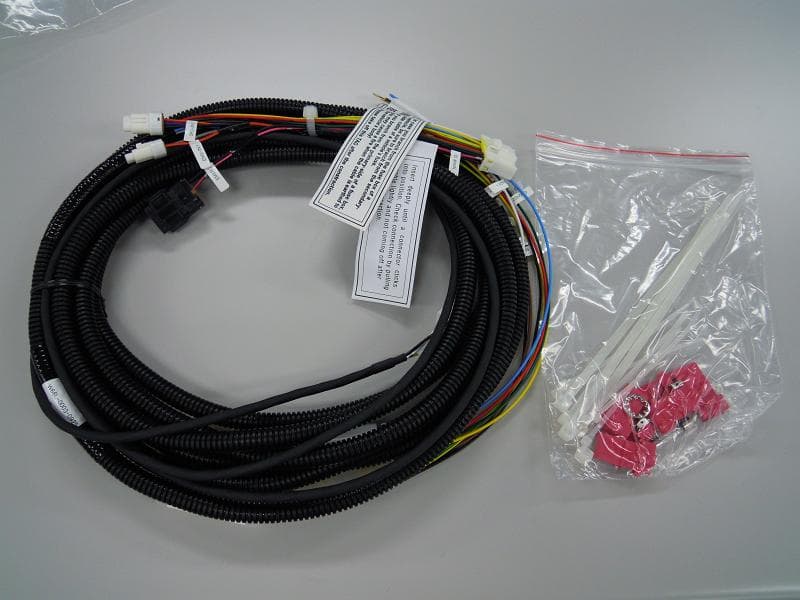
Click to zoom
Application Details
- Equipment Class
- PCB - PCS Licensed Transmitter
- Date of Grant
- Sep 08, 2011
- Application Purpose
- Original Equipment
- Date of Application
- Sep 08, 2011
- Equipment Note
- Wireless digital tachograph
- Frequency Range
- 1852.40000000 - 1907.60000000
- Company
- Transtron Inc.
- Country
- Japan
Documents & Files
Document Text
Text extracted from the exhibit documents filed with the FCC. Open a document above to read the original.
Users Manual
1 DTS-C2 Operation manual 【W01P-6300-C630,01版】 本マニュアルは、再生紙を使用しています。 1.Precautions for using this device. ・ Since this device uses wireless transmission, it may not function in locations where it is difficult for radio waves to penetrate, such as tunnels, underground passages and some buildings, in areas where radio waves are weak, or out of service are of GSM. Also, communication may be interrupted even when the signal meter on the device indicates there are strong radio waves and you are not moving (traveling). ・ Since this device uses radio waves to send the data, it is possible that a third party may attempt to tap your data. However, the GSM system automatically applies a confidential communication function to all data transmissions, so even if a third party could somehow tap the transmission, they find only meaningless data. ・ Since this device uses wireless transmission, when you are operating the device while moving to a location subject to weaker radio wave condition, the transmitted digital data may not be correctly decoded and as a result the decoded data may differ somewhat from the actual data. ・ The user hereby agrees that we do not make any representation and warranty for the pure economic loss or damages caused by the loss of data communication, which are happened by the illegal or mal function of the device, or external factors such as power failure. 2.Precautions for safety (Always follow these directions) ・ Before using this device, please read the following precautions to ensure safe use and handling. After reading this manual, keep it in a safe place. ・ These precautions are intended to protect you and others around you. Please read and follow them carefully to avoid injury, damage to the product or damage to property. ・ The signs below differentiate between the levels of danger that can occur if the product is not used within the specified guidelines. This sign denotes that death or serious injury may directly result from improper use. This sign denotes that death or serious injury may result from improper use. This sign denotes that bodily injury or damage to property may result from improper use. ・The symbols below show specific directions. This symbol denotes that the action is prohibited. This symbol denotes that disassembling this device is not allowed. This symbol denotes that using this device in the water-splashing place or to get wet is not allowed. This symbol denotes that an instruction must be obeyed at all times. DTS-C2 Operation Manual 2 DTS-C2 Operation manual 【W01P-6300-C630,01版】 本マニュアルは、再生紙を使用しています。 3.For handling of this device Please do not disassemble or remodel the device. May cause fire, injuries, electric shock, or mal-function. Please do not let the device get wet. Contact with water or other liquids may cause heating, electric shock, fire, mal-functions or injuries. Please take care of the place for use and treatment of the device. Please do not throw, drop, or give hard shock to the device. May cause the device to mal-function, or fire. Please keep conductive materials (metal pieces, pencil lead, etc.) from external connection jack. Please do not put those materials inside the device. May cause fire, mal-functions, or injuries subject to electrical short. If the equipment starts giving off a strange smell, overheats, becomes discolored or deformed during use, charging of in storage, please immediately turn the device OFF, and remove the power cable from the device. May cause fire, electric shock, or mal-functions. Please turn the device OFF near high-precision electronic control equipment or electronic equipment using low-power signals. May cause the electronic equipment to avoid. ※Examples of electronic equipment that I would like you to note it Healing aids, implanted pacemakers or defibrillators, other electronic medical equipment. Users wearing these electronic medical equipment should check with the manufacture or sales outlet about the effect of radio frequencies on the device. Please do not put magnetic card close to the device or the external antenna. May cause loss of data in bank card, credit card, phone card, or floppy disk. Please do not put foreign objects such as liquid like water, metal pieces or burnable things into the connectors of the device. May cause fire, electric chock, or mal-function. Please use only designated SIM card for the device. Moreover, please do not pulling out or insertion of the SIM card, while the power of the device ON. May cause the damage of SIM card. 3 DTS-C2 Operation manual 【W01P-6300-C630,01版】 本マニュアルは、再生紙を使用しています。 4.For handling this device in the vicinity of a electric medical equipment These precautions are based on the guidelines produced at the Electromagnetic Compatibility Conference Japan, regarding the protection of electronic medical equipment form radio from radio waves emitted by mobile phone units. Wearers of implanted pacemakers or defibrillators must install and use the external antenna of the device at least 22cm away from the implanted device. The signals of the device may affect the operation of implanted pacemakers or defibrillators, and other devices. 5.For using Bluetooth function ・ In the bandwidth used by this device, in addition to home electric appliances such as a microwave oven and industrial / scientific / medical devices, in-plant radio stations used to identify mobile objects used in production lines of a factory that require a license, specified low power radio stations, or amateur ratio stations that do no require a license (hereafter "other radio stations") can be in operation. 1. Before using Bluetooth function of the device, check whether other radio stations are in operation in your neighbourhood. 2. If radio wave interference occurs between the terminal and "other radio stations", use the terminal in a different location or turn the power OFF to avoid the radio wave interference. 6.Handling Precautions (1) "Information transmission medium" of the digital tachogra…
Text truncated - open the document above for the full version.
ID Label/Location Info
M o d e l n a m e : W 0 1 B - 6 3 0 0 - D 6 3 0 F C C I D : Y 9 O - D T S C 2 I C : 9 5 1 8 A - D T S C 2 A L A R M D A T A M 5 × 8 L M A X M o d e l n a m e : W 0 1 B - 6 3 0 0 - D 6 3 0 F C C I D : Y 9 O - D T S C 2 I C : 9 5 1 8 A - D T S C 2 W 0 1 B - 6 3 0 0 - D 6 3 0 / 0 1 D T S - C 2 1 1 - 0 2 - 0 1 0 1 6 3 0 0 0 0 0 1 6 3 0 0 0 0 0 1 U D T S - C 2
RF Exposure Info
Equipment Identification: FCC ID: Y9O-DTSC2 Prediction of MPE This device is to be used only for fixed and mobile applications. The antenna(s) used for this transmitter must be installed to provide a separation distance of at least 20 cm from all the persons and must not be co-located or operating in conjunction with any other antenna or transmitter. The table below is excerpted from Table 1B of 47 CFR 1.1310 titled Limits for Maximum Permissible Exposure (MPE), Limits for General Population/Uncontrolled Exposure: Frequency Range (MHz) Power density (mW/cm 2 ) Averaging time (minutes) 300 – 1500 f (MHz) /1500 30 1500 – 100.000 1.0 30 Based on the above table the limits are: For 850 MHz frequency band device: 0.57 mW/cm 2 For 1900 MHz frequency band device: 1 mW/cm 2 § 2.1091: The limit for 850 MHz mobile operations where no routine evaluation is required is: 1.5W ERP The limit for 1700 / 1900 MHz mobile operations where no routine evaluation is required is: 3W EIRP Max permissive power according to §24.232 : 2W EIRP Max permissive power according to §§22.913 (a): 7W ERP Using the equation from page 19 of OET Bulletin 65, Edition 97-01: 2 4R PG S π = where: S = power density (in appropriate units, e.g. mW/cm 2 ) P = power input to the antenna (in appropriate units, e.g., mW) G = power gain of the antenna in the direction of interest relative to an isotropic radiator R = distance to the center of radiation of the antenna (appropriate units, e.g., cm) Compliance with MPE limits can be guaranteed as the calculation below shows: Equipment Identification: FCC ID: Y9O-DTSC2 850 MHz frequency band Maximum output power considerations: Mode Maximum conducted output power (dBm) Maximum conducted output power (mW) Duty cycle Equivalent conducted output power (Maximum conducted output power x duty cycle) (mW) GPRS 32.3 dBm 1698.2 25% 424.6 EDGE 27.8 dBm 602.6 25% 150.6 WCDMA 27 dBm 501.2 100%501.2 HSDPA 100% HSUPA 100% P Maximum power input to the antenna: 1659.6 mW R Distance: 20 cm S MPE limit for uncontrolled exposure: 0,57 mW/cm 2 G 1 Antenna gain (dBi) to comply with MPE limits: 7.5 dBi ERP power limit according to §2.1091: 1,5 W ERP G 2 Antenna gain (dBi) to comply with ERP limits: 6.9 dBi (ERP = Equivalent conductedoutput power x Antenna gain / 1,64) ERP power limit according to §22.913: 7 W ERP G 3 Antenna gain (dBi) to comply with ERP limits: 8.3 dBi (ERP = Maximum conducted output power x Antenna gain / 1,64) G 850 MHz band Min (G 1 , G 2, G 3 ) 6.9 dBi Therefore the maximum antenna gain for mobile operation to comply with MPE and ERP limits shall not exceed 6.9 dBi. Prediction for Part 22 Maximum radiated power EIRP: 31.8dBm (1514 mW) @ 836.6MHz Lowest limit for 850 MHz fixed operations (@20cm) where no routine evaluation is required is § 1.1310: (f/1500)mW/cm 2 =0.5659 mW/cm 2 Calculated at distance of 20cm for reference antenna: Power density = 1514 / (4 x pi x 20 2 ) = 0.3013 mW/cm 2 Result: Configuration complies with rules as power density is below MPE limit. Equipment Identification: FCC ID: Y9O-DTSC2 1900 MHz frequency band Maximum output power considerations: Mode Maximum conducted output power (dBm) Maximum conducted output power (mW) Duty cycle Equivalent conducted output power (Maximum conducted output power x duty cycle) (mW) GPRS 30 1000 25% 250 EDGE 28 630.9 25% 157.7 WCDMA 26.9 489.8 100%489.8 HSDPA 100% HSUPA 100% P Maximum power input to the antenna: 489.8 mW R Distance: 20 cm S MPE limit for uncontrolled exposure: 1 mW/cm 2 G 1 Antenna gain (dBi) to comply with MPE limits: 10.1 dBi EIRP power limit according to §2.1091: 3 W EIRP G 2 Antenna gain (dBi) to comply with ERP limits: 10 dBi (EIRP = Equivalent conducted output power x Antenna gain ) EIRP power limit according to §24.232: 2 W EIRP G 3 Antenna gain (dBi) to comply with EIRP limits: 3 dBi (EIRP = Maximum conducted output power x Antenna gain) G 1900 MHz band Min (G 1 , G 2, G 3 ) 3 dBi Therefore the maximum antenna gain for mobile operation to comply with MPE and ERP limits shall not exceed 3 dBi. Prediction for Part 24 Maximum radiated power EIRP: 32.2 dBm (1660mW) @1880MHz Lowest limit for 1900 MHz fixed operations (@20cm) where no routine evaluation is required is § 1.1310 : 1 mW/cm 2 Calculated at distance of 20cm: Power density = 1660 / (4 x pi x 20 2 ) = 0.3303 mW/cm 2 Result: Configuration complies with rules as power density is below MPE limit. Equipment Identification: FCC ID: Y9O-DTSC2 Date: 2011-08-24 Name: Christopher Torio Title: EMC Engineer Company: Cetecom Inc.
Test Report
7 layers AG Aufsichtsratsvorsitzenderh Registergerichth registered in: Borsigstrasse 11 Chairman of the Supervisory Board: Düsseldorf, HRB 44096 40880 Ratingen, Germany Markus Becker USt-IdNr h VAT Nr: Phone: +49 (0) 2102 749 0 Vorstandh Board: DE 203159652 Fax: +49 (0) 2102 749 350 Dr. Hans-Jürgen Meckelburg www.7Layers.com René Schildknecht InterLab is a registered trademark of 7 layers AG FCC Measurement/Technical Report on GSM/UMTS module Siemens Cellular Engine HC25 Report Reference: MDE_Siem_0605_FCCb Test Laboratory: 7 layers AG Borsigstrasse 11 40880 Ratingen Germany email: [email protected] DAT-P-192/99-01 Note: The following test results relate only to the devices specified in this document. This report shall not be reproduced in parts without the written approval of the testing laboratory. Test report Reference: MDE_Siem_0605_FCCb Page 2 of 67 Table of Contents 0 Summary 3 0.1 Technical Report Summary 3 0.2 Measurement Summary 4 1 Administrative Data 6 1.1 Testing Laboratory 6 1.2 Project Data 6 1.3 Applicant Data 6 1.4 Manufacturer Data 6 2 Testobject Data 7 2.1 General EUT Description 7 2.2 EUT Main components 8 2.3 Ancillary Equipment 8 2.4 EUT Setups 8 2.5 Operating Modes 9 3 Test Results 10 3.1 RF Power Output 10 3.2 Frequency stability 14 3.3 Spurious emissions at antenna terminals 20 3.4 Field strength of spurious radiation 24 3.5 Emission and Occupied Bandwidth 28 3.6 Band edge compliance 32 4 Test Equipment 35 5 Photo Report 38 6 Setup Drawings 42 7 Annex 44 Measurement Plots Test report Reference: MDE_Siem_0605_FCCb Page 3 of 67 0 Summary 0.1 Technical Report Summary Type of Authorization Certification for a GSM cellular radiotelephone device Applicable FCC Rules Prepared in accordance with the requirements of FCC Rules and Regulations as listed in 47 CFR Ch.1 Parts 0 to 19 and Parts 20 to 69 (10-1-06 Edition). The following subparts are applicable to the results in this test report. Part 2 Subpart J - Equipment Authorization Procedures, Certification § 2.1046 Measurement required: RF power output § 2.1049 Measurement required: Occupied bandwidth § 2.1051 Measurement required: Spurious emissions at antenna terminals § 2.1053 Measurement required: Field strength of spurious radiation § 2.1055 Measurement required: Frequency stability § 2.1057 Frequency spectrum to be investigated Part 22 Subpart C – Operational and Technical Requirements § 22.355 Frequency tolerance Subpart H – Cellular Radiotelephone Service § 22.913 Effective radiated power limits § 22.917 Emission limitations for cellular equipment Summary Test The EUT complied with all performed tests as listed in chapter 0.2 Measurement Summary. Test report Reference: MDE_Siem_0605_FCCb Page 4 of 67 0.2 Measurement Summary RF Power Output The measurement was performed according to FCC §2.1046 10-1-06 OP-Mode Setup Port Final Result op-mode 1 setup_a01 antenna connector passed op-mode 2 setup_a01 antenna connector passed op-mode 3 setup_a01 antenna connector passed op-mode 4 setup_a01 antenna connector passed op-mode 5 setup_a01 antenna connector passed op-mode 6 setup_a01 antenna connector passed op-mode 7 setup_a01 antenna connector passed op-mode 8 setup_a01 antenna connector passed op-mode 9 setup_a01 antenna connector passed Frequency stability The measurement was performed according to FCC §2.1055 10-1-06 OP-Mode Setup Port Final Result op-mode 2 setup_a01 antenna connector passed op-mode 5 setup_a01 antenna connector passed op-mode 8 setup_a01 antenna connector passed Spurious emissions at antenna terminals The measurement was performed according to FCC §2.1051 10-1-06 OP-Mode Setup Port Final Result op-mode 1 setup_a01 antenna connector passed op-mode 2 setup_a01 antenna connector passed op-mode 3 setup_a01 antenna connector passed op-mode 4 setup_a01 antenna connector passed op-mode 5 setup_a01 antenna connector passed op-mode 6 setup_a01 antenna connector passed op-mode 7 setup_a01 antenna connector passed op-mode 8 setup_a01 antenna connector passed op-mode 9 setup_a01 antenna connector passed Field strength of spurious radiation The measurement was performed according to FCC §2.1053 10-1-06 OP-Mode Setup Port Final Result op-mode 1 setup_a02 enclosure passed op-mode 2 setup_a02 enclosure passed op-mode 3 setup_a02 enclosure passed op-mode 4 setup_a02 enclosure passed op-mode 5 setup_a02 enclosure passed op-mode 6 setup_a02 enclosure passed op-mode 7 setup_a02 enclosure passed op-mode 8 setup_a02 enclosure passed op-mode 9 setup_a02 enclosure passed Test report Reference: MDE_Siem_0605_FCCb Page 6 of 67 1 Administrative Data 1.1 Testing Laboratory Company Name: 7 Layers AG Address Borsigstr. 11 40880 Ratingen Germany This facility has been fully described in a report submitted to the FCC and accepted under the registration number 96716 . The test facility is also accredited by the following accreditation organisation: - Deutscher Akkreditierungs Rat DAR-Registration no. DAT-P-192/99-01 Responsible for Accreditation Scope: Dipl.-Ing. Bernhard Retka Dipl.-Ing. Robert Machulec Dipl.-Ing. Thomas Hoell Report Template Version: 2006-12-18 1.2 Project Data Responsible for testing and report: Dipl.-Ing. Andreas Petz Date of Test(s): 2007-02-09 to 2007-03-02 Date of Report: 2007-03-15 1.3 Applicant Data Company Name: Siemens AG Address: Siemensdamm 50 13629 Berlin Germany Contact Person: Mr. Hussein Halawi 1.4 Manufacturer Data Company Name: please see applicant data Address: Contact Person: Test report Reference: MDE_Siem_0605_FCCb Page 7 of 67 2 Testobject Data 2.1 General EUT Description Equipment under Test: GSM/UMTS module Type Designation: Siemens Cellular Engine HC25 Kind of Device: (optional) GSM 850/900/1800/1900 + UMTS FDD I/II/V module Voltage Type: DC Nominal Voltage: 4.2 V Maximum Voltage: 4.2 V Minimum Voltage: 3.2 V General product description: The Equipment Under Test (EUT) is a GSM 850/900/1800/1900 module and supports EDGE and FDD I/II/V. The manufacturer declared that nominal voltage is equal …
Text truncated - open the document above for the full version.
Test Report
7 layers AG Aufsichtsratsvorsitzenderh Registergerichth registered in: Borsigstrasse 11 Chairman of the Supervisory Board: Düsseldorf, HRB 44096 40880 Ratingen, Germany Markus Becker USt-IdNr h VAT Nr: Phone: +49 (0) 2102 749 0 Vorstandh Board: DE 203159652 Fax: +49 (0) 2102 749 350 Dr. Hans-Jürgen Meckelburg www.7Layers.com René Schildknecht InterLab is a registered trademark of 7 layers AG FCC Measurement/Technical Report on GSM/UMTS module Siemens Cellular Engine HC25 Report Reference: MDE_Siem_0605_FCCa Test Laboratory: 7 layers AG Borsigstrasse 11 40880 Ratingen Germany email: [email protected] DAT-P-192/99-01 Note: The following test results relate only to the devices specified in this document. This report shall not be reproduced in parts without the written approval of the testing laboratory. Test report Reference: MDE_Siem_0605_FCCa Page 2 of 67 Table of Contents 0 Summary 3 0.1 Technical Report Summary 3 0.2 Measurement Summary 4 1 Administrative Data 6 1.1 Testing Laboratory 6 1.2 Project Data 6 1.3 Applicant Data 6 1.4 Manufacturer Data 6 2 Testobject Data 7 2.1 General EUT Description 7 2.2 EUT Main components 8 2.3 Ancillary Equipment 8 2.4 EUT Setups 8 2.5 Operating Modes 9 3 Test Results 10 3.1 RF Power Output 10 3.2 Frequency stability 14 3.3 Spurious emissions at antenna terminals 20 3.4 Field strength of spurious radiation 24 3.5 Emission and Occupied Bandwidth 28 3.6 Band edge compliance 32 4 Test Equipment 35 5 Photo Report 38 6 Setup Drawings 42 7 Annex 44 Measurement Plots Test report Reference: MDE_Siem_0605_FCCa Page 3 of 67 0 Summary 0.1 Technical Report Summary Type of Authorization Certification for a GSM cellular radiotelephone device Applicable FCC Rules Prepared in accordance with the requirements of FCC Rules and Regulations as listed in 47 CFR Ch.1 Parts 0 to 19 and Parts 20 to 69 (10-1-06 Edition). The following subparts are applicable to the results in this test report. Part 2 Subpart J - Equipment Authorization Procedures, Certification § 2.1046 Measurement required: RF power output § 2.1049 Measurement required: Occupied bandwidth § 2.1051 Measurement required: Spurious emissions at antenna terminals § 2.1053 Measurement required: Field strength of spurious radiation § 2.1055 Measurement required: Frequency stability § 2.1057 Frequency spectrum to be investigated Part 24 Subpart E - Broadband PCS § 24.232 Power and antenna height limits § 24.235 Frequency stability § 24.236 Field strength limits § 24.238 Emission limitations for Broadband PCS equipment Summary Test Results: The EUT complied with all performed tests as listed in chapter 0.2 Measurement Summary. Test report Reference: MDE_Siem_0605_FCCa Page 4 of 67 0.2 Measurement Summary RF Power Output The measurement was performed according to FCC §2.1046 10-1-06 OP-Mode Setup Port Final Result op-mode 1 setup_a01 antenna connector passed op-mode 2 setup_a01 antenna connector passed op-mode 3 setup_a01 antenna connector passed op-mode 4 setup_a01 antenna connector passed op-mode 5 setup_a01 antenna connector passed op-mode 6 setup_a01 antenna connector passed op-mode 7 setup_a01 antenna connector passed op-mode 8 setup_a01 antenna connector passed op-mode 9 setup_a01 antenna connector passed Frequency stability The measurement was performed according to FCC §2.1055 10-1-06 OP-Mode Setup Port Final Result op-mode 2 setup_a01 antenna connector passed op-mode 4 setup_a01 antenna connector passed op-mode 8 setup_a01 antenna connector passed Spurious emissions at antenna terminals The measurement was performed according to FCC §2.1051 10-1-06 OP-Mode Setup Port Final Result op-mode 1 setup_a01 antenna connector passed op-mode 2 setup_a01 antenna connector passed op-mode 3 setup_a01 antenna connector passed op-mode 4 setup_a01 antenna connector passed op-mode 5 setup_a01 antenna connector passed op-mode 6 setup_a01 antenna connector passed op-mode 7 setup_a01 antenna connector passed op-mode 8 setup_a01 antenna connector passed op-mode 9 setup_a01 antenna connector passed Field strength of spurious radiation The measurement was performed according to FCC §2.1053 10-1-06 OP-Mode Setup Port Final Result op-mode 1 setup_a02 enclosure passed op-mode 2 setup_a02 enclosure passed op-mode 3 setup_a02 enclosure passed op-mode 4 setup_a02 enclosure passed op-mode 5 setup_a02 enclosure passed op-mode 6 setup_a02 enclosure passed op-mode 7 setup_a02 enclosure passed op-mode 8 setup_a02 enclosure passed op-mode 9 setup_a02 enclosure passed Test report Reference: MDE_Siem_0605_FCCa Page 6 of 67 1 Administrative Data 1.1 Testing Laboratory Company Name: 7 Layers AG Address Borsigstr. 11 40880 Ratingen Germany This facility has been fully described in a report submitted to the FCC and accepted under the registration number 96716 . The test facility is also accredited by the following accreditation organisation: - Deutscher Akkreditierungs Rat DAR-Registration no. DAT-P-192/99-01 Responsible for Accreditation Scope: Dipl.-Ing. Bernhard Retka Dipl.-Ing. Robert Machulec Dipl.-Ing. Thomas Hoell Report Template Version: 2006-12-18 1.2 Project Data Responsible for testing and report: Dipl.-Ing. Andreas Petz Date of Test(s): 2007-02-09 to 2007-03-02 Date of Report: 2007-03-16 1.3 Applicant Data Company Name: Siemens AG Address: Siemensdamm 50 13629 Berlin Germany Contact Person: Mr. Hussein Halawi 1.4 Manufacturer Data Company Name: please see applicant data Address: Contact Person: Test report Reference: MDE_Siem_0605_FCCa Page 7 of 67 2 Testobject Data 2.1 General EUT Description Equipment under Test: GSM/UMTS module Type Designation: Siemens Cellular Engine HC25 Kind of Device: (optional) GSM 850/900/1800/1900 + UMTS FDD I/II/V module Voltage Type: DC Nominal Voltage: 4.2 V Maximum Voltage: 4.2 V Minimum Voltage: 3.2 V General product description: The Equipment Under Test (EUT) is a GSM 850/900/1800/1900 module and supports EDGE and FDD I/II/V. The manufacturer declared that nominal voltage is equal to maximum voltage. In P…
Text truncated - open the document above for the full version.
Test Report
Bluetooth Qualification Test Facility (BQTF) FCC listed: A2LA Accredited IC recognized # 3462B-1 CETECOM Inc. 411 Dixon Landing Road Milpitas, CA 95035 U.S.A. Phone: + 1 (408) 586 6200 Fax: + 1 (408) 586 6299 E-mail: [email protected] http://www.cetecom.com CETECOM Inc. is a Delaware Corporation with Corporation number: 2113686 Board of Directors: Dr. Harald Ansorge, Hans Peter May. V3.0 2010-10-30 The BLUETOOTH trademarks are owned by Bluetooth SIG, Inc., U.S.A. and licensed to CETECOM Inc. © Copyright by CETECOM FCC/IC Test Report FOR: Model Name: W01B-6300-D630 Wireless Digital Tachograph FCC ID: Y9O-DTSC2 IC ID: 9518A-DTSC2 47 CFR Part 2, 22, 24 RSS-132 Issue 2 RSS-133 Issue 5 TEST REPORT #: EMC_CET10_074_11501_FCC_22_24_Rev4 DATE: 2011-09-06 Test Report #: EMC_ CET10_074_11501_22_24_Rev4 FCC ID: Y9O-DTSC2 Date of Report : 2011-09-06 Page 2 of 75 Table of Contents 1 Assessment .............................................................................................................................. 3 2 Administrative Data ............................................................................................................... 4 2.1 Identification of the Testing Laboratory Issuing the EMC Test Report ......................................... 4 2.2 Identification of the Client ............................................................................................................. 4 2.3 Identification of the Manufacturer ................................................................................................. 4 3 Equipment under Test (EUT) ............................................................................................... 5 3.1 Specification of the Equipment under Test .................................................................................... 5 3.2 Identification of the Equipment Under Test (EUT) ....................................................................... 6 3.3 Identification of Accessory equipment ........................................................................................... 6 4 Subject of Investigation ......................................................................................................... 7 5 Summary of Measurement Results ....................................................................................... 8 6 Measurements ....................................................................................................................... 10 6.1 RF Power Output .......................................................................................................................... 10 6.1.1 References ............................................................................................................................ 10 6.1.2 Measurement requirements: ................................................................................................. 10 6.1.3 Limits: .................................................................................................................................. 10 6.1.4 Conducted Output Power Measurement procedure ............................................................. 11 6.1.5 Radiated Output Power Measurement procedure ................................................................ 12 6.1.6 RF Power Output 850MHz band .......................................................................................... 13 6.1.7 RF Power Output 1900MHz band ........................................................................................ 14 6.1.8 Results .................................................................................................................................. 15 6.2 Occupied Bandwidth/Emission Bandwidth .................................................................................. 33 6.3 Frequency Stability ...................................................................................................................... 33 6.4 Conducted Spurious Emissions .................................................................................................... 33 6.5 Spurious Emissions Radiated ....................................................................................................... 34 6.5.1 References ............................................................................................................................ 34 6.5.2 Measurement requirements: ................................................................................................. 34 6.5.3 Limits: .................................................................................................................................. 34 6.5.4 Radiated out of band measurement procedure: ................................................................... 36 6.5.5 Radiated out of band emissions results on EUT- Transmit Mode: ...................................... 38 6.6 Radiated out of band emissions results on EUT- Receive Mode: ................................................ 69 6.6.1 References ............................................................................................................................ 69 6.6.2 Limits .................................................................................................................................... 69 6.6.3 Measurement settings: .......................................................................................................... 69 6.6.4 Results .................................................................................................................................. 69 6.7 AC Power Line Conducted Emissions ......................................................................................... 72 6.7.1 References: ........................................................................................................................... 72 6.7.2 Limits: ..........................................................................................................…
Text truncated - open the document above for the full version.
Test Setup Photos
V2.0 2009-10-30 The BLUETOOTH trademarks are owned by Bluetooth SIG, Inc., U.S.A. and licensed to CETECOM Inc. © Copyright by CETECOM Test Setup Pictures Model: W01B-6300-D630 FCC ID: Y90-DTSC2 IC ID: 9518A-DTSC2 TEST REPORT #: EMC_CET10_074_11501_22_24 Project #: EMC_CET10_074_11501 FCC ID: Y90-DTSC2 Date: 2011-08-15 Page 2 of 4 EIRP Test Setup Pictures FCC22/24 Project #: EMC_CET10_074_11501 FCC ID: Y90-DTSC2 Date: 2011-08-15 Page 3 of 4 Radiated Spurious Emissions Test Setup Pictures 30-1000MHz Project #: EMC_CET10_074_11501 FCC ID: Y90-DTSC2 Date: 2011-08-15 Page 4 of 4 1-18GHz
Contact Information
Applicant
Toshihiro Fujita(Engineer)
Test Firm
CETECOM Inc.Meinolf Glunz
[email protected]408-586-6301
Technical Specifications
| # | Rule Parts | Frequency Range | Power Output | Emission | Tolerance |
|---|---|---|---|---|---|
| 6 | 24E | 1.85 GHz - 1.91 GHz | 490.00 mW | 4M20F9W | 38 Hz |