Y9XHPIRACING000013CH 2.4GHz FHSS RADIO SYSTEM
Hobby Products International Inc.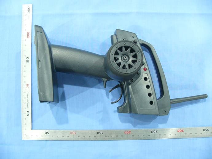
Click to zoom
Application Details
- Equipment Class
- DSS - Part 15 Spread Spectrum Transmitter
- Date of Grant
- Mar 30, 2011
- Application Purpose
- Original Equipment
- Date of Application
- Mar 30, 2011
- Equipment Note
- 3CH 2.4GHz FHSS RADIO SYSTEM
- Frequency Range
- 2407.00000000 - 2477.00000000
- Country
- United States
Documents & Files
Document Text
Text extracted from the exhibit documents filed with the FCC. Open a document above to read the original.
Users Manual
2.4GHz FHSS radio system instruction manual 2.4GHz Pistol Radio Set 2 This equipment has been tested and found to comply with the limits for a Class B digital device, pursuant to part 15 of the FCC Rules. These limits are designed to provide reasonable protection against harmful interference in a residential installation. This equipment generates, uses, and can radiate radio frequency energy and, if not installed and used in accordance with the operating instructions, may cause harmful interference to radio communications, however, there is no guarantee that interference will not occur in a particular installation. If this equipment does cause harmful interference to radio or television reception, which can be determined by turning the equipment off and in, the user is encouraged to try to correct the interference by one or more of the following measures: ● Reorient or relocate the receiving antenna. ● Increase the separation between the equipment and the receiver. ● Connect the equipment into an outlet on a circuit different from that to which the receiver is connected. ● Consult the dealer or an experienced technician for help. This device complies with Part 15 of the FCC Rules and with RSS-210 of lndustry Canada. Operation is subject to the following two conditions: 1)This device may not cause harmful interference, and 2)This device must accept any interference received, including interference that may cause undesired operation. WARNING: Changes or modifications made to this equipment not expressly approved by the party responsible for compliance may void the FCC authorization to operate this equipment. RF Exposure Statement The TF-40 transmitter has been tested and meets the FCC RF exposure guidelines when used with the accessories supplied or designated for this product, and provided at least 20cm separation between the antenna the user\s body is maintained. Use of other accessories may not ensure compliance with FCC RF exposure guidelines. FCC COMPLIANCE STATEMENTFCC COMPLIANCE STATEMENT NAME OF EACH PARTNAME OF EACH PART TRANSMITTER TF-40 When replacing the battery. Slide the cover downward while pressing the part marked “ ”. RECEIVER RF-40RECEIVER RF-40 * Please noted the transmitter does not have charging function, 4"AA” alkaline dry cells required. .. 3 BATTERY COVER Bind ON/OFF switch 3CH switch LED LEDLED AntennaAntenna Binding ButtonBinding Button Steering wheel Throttle trigger Reverse Switch CH.1 (ST) CH.2 (TH) D/R CH1 (ST)L CH1 (ST)R CH2 (TH)L CH2 (TH)H TRIM EPA CH3 CH2 CH1 SPECTIAL NOTE FOR 2.4GHZ FHSS RADIO SYSTEM SETUPSPECTIAL NOTE FOR 2.4GHZ FHSS RADIO SYSTEM SETUP Since the 2.4GHz have different characteristics than that of the conventional frequencies, please read this section carefully to enjoy safe flight with the 2.4GHz system. The wavelength of the 2.4GHz is much shorter than that of the conventional frequencies, it is very susceptible to loss of signal which results in a receiving error. In order to avoid this phenomenon, please must follow the receiver antenna installation shown as below. . . RECEIVER’S ANTENNA INSTALLATIONRECEIVER’S ANTENNA INSTALLATION 4 Use this when performing left and right steering angle adjustments, throttle high side/brake side operation amount adjustment. - Corrects the maximum steering angle and left and right steering angles when there is a difference in the turning radius due to the characteristics, etc. of the vehicle. Maximum steering angle adjustment (The EPA function basically determines the maximum steering angle of each channel in each direction.) Adjustment: Range: 50~150% of each direction. Use the small plastic tool (-) to turn the two small knobs inside the control panel upper right as shown to make adjustments of the steering angle of each direction. (Caution: The servo reverse switches will effect to the directions) Caution! Decide the EPA value at the contact point of your vehicle steering system construction. When trim the EPA, be sure that the steering servo does not bind at the maximum steering angle. Throttle (forward, brake side/reverse side) adjustment. Adjustment: Range: 50~150% of each direction. Use the small plastic tool (-) to turn the plastic tool small knobs inside the control panel lower side as shown to make adjustments of the control range of each direction. (Caution: The servo reverse switches will effect to the directions) Caution! If the throttle channel is connected to an ESC, read your ESC manual to decide the EPA value for your vehicle. END POINT ADJUSTMENT / EPAEND POINT ADJUSTMENT / EPA 5 1. The antenna must be kept as straight up as possible. Otherwise it will reduce the effective range. 2. The antenna should be placed at 90 degrees to the receiver case. 3. The antenna must be kept away from conductive materials, such as metal and carbon by at least a half inch. The coaxial part of the antennas does not need to follow these guidelines, but do not bend it in a small radius. 4. Keep the antenna away from the motor, ESC, and other noise sources as much as possible. *This photo demonstrates how the antenna should be placed. For actual installation the receiver must be wrapped with a sponge or placed with floating material to protect it from vibration . The receiver contains precision electronic parts. It is the most delicate radio component on-board the model and should be protected from vibration, shock and temperature extremes. To protect the receiver, wrap it in R/C foam rubber or other vibration-absorbing material. If appropriate, waterproof the receiver by placing it in a plastic bag and closing the open end with a rubber band before wrapping it on chassis. If moisture enters the receiver, intermittent operation or a failure may result. Wrapping the receiver in a plastic bag also protects it from fuel and exhaust residue which, in some cars, can work its way into the body. . . TRANSMITTER ANTENNATRANSMITTER ANTENNA 1. The transmitter antenna is adjustable so please make sure the antenna is nev…
Text truncated - open the document above for the full version.
Attestation Statements
Statement of Declaration FCC ID:Y9XHPIRACING00001 Product:3CH 2.4GHz FHSS RADIO SYSTEM Model:TF-40 1. Output power and channel separation of a Hopping device in the operating mode: In the operating mode, device turn on the RF carrier, TX data with GFSK modulation, in this method, each bit of data in a byte is encoded with multiple bits using a Pseudo Noise code(PN code).In this way the transmitters and receivers must use the same PN code and channel to communicate, then turn off the RF carrier with the specification of Dwell time. The output power and the channel spacing is not change in the operating mode. 2. Frequency range of a Hopping device: Hereby we declare that the frequency range of this device is :2407~2477MHz. 3. Example of a hopping sequence in operating mode: Example of an operating mode with 71 hopping sequences: 13,9,5,17,29,25,21,33,45,41,37,49,61,57,53,65,6,73,69,10,22,18,14,26,38,34,30, 42,54,50,46,58,70,66,62,74,15,11,7,19,8,12,16,20,75,24,28,72,31,71,68,23,67,27 ,32,64,35,63,32,60,52,59,36,40,55,51,39,48,56,43,47. 4.Dwell time in operating mode The dwell time in operating mode is independent from the TX data. The calculation for a period is as follows:Dwell time=time slot length *number of hopping channels. The time of occupancy in the specified 28.4 second period (71 channel *0.4s) is equal to 28.4*(# of pulse in 28.4s/28.4)*pulse width. Pulse width=9.4ms;#pulse in 28.4s=13; Time of occupancy=28.4* (13/28.4)* 9.4=122.2ms≤400ms 5. Channel Separation in operating mode The normal channel spacing of the Hopping system is 1MHz independent of the operating mode.
External Photos
Report No: SZ101116B01 Page 1 /3 TX Report No: SZ101116B01 Page 2 /3 Report No: SZ101116B01 Page 3 /3
Internal Photos
Report No: SZ101116B01 Page 1 / 5 TX Report No: SZ101116B01 Page 2 / 5 Report No: SZ101116B01 Page 3 / 5 Report No: SZ101116B01 Page 4 / 5 Report No: SZ101116B01 Page 5 / 5
Test Report
Report No: SZ101116B01-RP FCC ID: Y9XHPIRACING00001 Page 1 of 40 This report shall not be reproduced except in full, without the written approval of Compliance Certification Services. FCC 47 CFR PART 15 SUBPART C TEST REPORT For 3CH 2.4GHz FHSS RADIO SYSTEM MODEL: TF-40 Brand : HPI Racing Test Report Number: SZ101116B01-RP Prepared for Hobby Products International Inc. 70 Icon St Foothill Ranch, CA 92610-3000 USA Prepared by Compliance Certification Services (Shenzhen) Inc. No.10-1,Mingkeda Logistics Park, NO.18, Huanguan south Rd., Guan lan Town, Baoan District, Shenzhen China TEL: 86-755-28055000 FAX: 86-755-28055221 Issued Date: January 10,2011 Note: This report shall not be reproduced except in full, without the written approval of Compliance Certification Services Inc. This document may be altered or revised by Compliance Certification Services Inc. personnel only, and shall be noted in the revision section of the document. The client should not use it to claim product endorsement by TAF, A2LA, NVLAP, NIST or any government agencies. The test result of this report relate only to the tested sample identified in this report. 检 测 CNAS L4818 Report No: SZ101116B01-RP FCC ID: Y9XHPIRACING00001 Page 2 of 40 This report shall not be reproduced except in full, without the written approval of Compliance Certification Services. Revision History Rev. Issue No. Revisions Effect Page Revised By 00 SZ101116B01-RP Initial Issue ALL Vincent Yao Report No: SZ101116B03-RP FCC ID: Y9XHPIRACING00001 Page 3 of 40 This report shall not be reproduced except in full, without the written approval of Compliance Certification Services. TABLE OF CONTENTS 1. TEST RESULT CERTIFICATION.............................................................................................. 4 2. EUT DESCRIPTION..................................................................................................................... 5 3. TEST METHODOLOGY.............................................................................................................. 6 3.1 DESCRIPTION OF TEST MODES............................................................................6 4. FACILITIES AND ACCREDITATIONS..................................................................................... 7 4.1 FACILITIES...............................................................................................................7 4.2 ACCREDITATIONS ..................................................................................................7 4.3 MEASUREMENT UNCERTAINTY............................................................................7 5. SETUP OF EQUIPMENT UNDER TEST.................................................................................. 8 5.1 SETUP CONFIGURATION OF EUT .........................................................................8 5.2 SUPPORT EQUIPMENT .........................................................................................8 6. FCC PART 15.247 REQUIREMENTS....................................................................................... 9 6.1 20DB BANDWIDTH ..................................................................................................9 6.2 PEAK POWER ........................................................................................................12 6.3 PWER POWER SPECTRAL DENSITY...................................................................14 6.4 BAND EDGES MEASUREMENT ............................................................................15 6.5 FREQUENCY SEPARATION .................................................................................21 6.6 NUMBER OF HOPPING FREQUENCY..................................................................23 6.7 TIME OF OCCUPANCY (DWELL TIME).................................................................25 6.8 SPURIOUS EMISSIONS .........................................................................................28 6.9 POWERLINE CONDUCTED EMISSIONS ..............................................................39 Report No: SZ101116B01-RP FCC ID: Y9XHPIRACING00001 Page 4 of 40 This report shall not be reproduced except in full, without the written approval of Compliance Certification Services. 1. TEST RESULT CERTIFICATION Product: 3CH 2.4GHz FHSS RADIO SYSTEM Model: TF-40 Brand: HPI Racing Tested: November 16,2010~January 8, 2011 Applicant: Hobby Products International Inc. 70 Icon St Foothill Ranch, CA 92610-3000 USA Manufacturer: Shanghai Merit Technology Corp. NO.1058 Taogan Road, Sheshan Town, Songjiang District, China,201602 APPLICABLE STANDARDS STANDARD TEST RESULT FCC 47 CFR Part 15 Subpart C No non-compliance noted We hereby certify that: The above equipment was tested by Compliance Certification Services Inc. The test data, data evaluation, test procedures, and equipment configurations shown in this report were made in accordance with the procedures given in ANSI C63.4: 2003 and the energy emitted by the sample EUT tested as described in this report is in compliance with conducted and radiated emission limits of FCC Rules Part 15.207, 15.209 and 15.247. The test results of this report relate only to the tested sample EUT identified in this report. Approved by: Reviewed by: Vincent Yao Manager Compliance Certification Service Inc. Aven Zhou Supervisor of Report Dept. Compliance Certification Service Inc. Report No: SZ101116B01-RP FCC ID: Y9XHPIRACING00001 Page 5 of 40 This report shall not be reproduced except in full, without the written approval of Compliance Certification Services. 2. EUT DESCRIPTION Product 3CH 2.4GHz FHSS RADIO SYSTEM Model Number TF-40 Trade Name HPI Racing Model Discrepancy N/A Identify Number SZ101116B01-RP Power Supply DC6V supplied by the battery(4*1.5V) Frequency Range 2407-2477MHz Received Date January 7,2011 Transmit Power -0.58dBm Modulation Technique FHSS Number of Channels 71 Channels Antenna Specification Dipole Antenna :2.0dBi (Max) Temperature Range 0°C ~ +55°C Note: Th…
Text truncated - open the document above for the full version.
Test Setup Photos
Report No.: SZ101116B01 Page 1 / 1 PHOTOGRAPHS OF THE TEST CONFIGURATION RADIATED EMISSION TEST TX
Contact Information
Applicant
HIROYUKI IIDA(Radio team manager)
Test Firm
Compliance Certification Services (Shenzhen) Inc.Harry Li
Technical Specifications
| # | Rule Parts | Frequency Range | Power Output |
|---|---|---|---|
| 1 | 15C | 2.41 GHz - 2.48 GHz | 870.00 µW |
Other Applications from Hobby Products International Inc.
Y9XHPIRACING00102
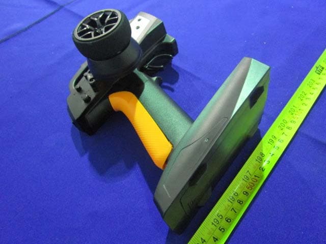
Sep 29, 20143CH 2.4GHz FHSS RADIO SYSTEM
Equipment Class
DSS - Part 15 Spread Spectrum Transmitter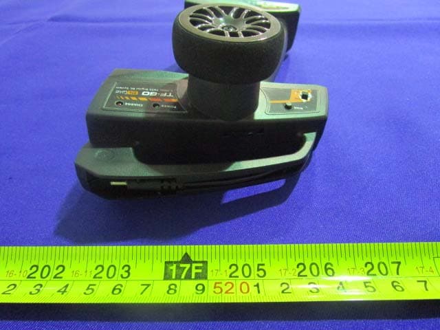
Y9XHPIRACING00101
Sep 28, 20142CH 2.4GHz FHSS RADIO SYSTEM
Equipment Class
DSS - Part 15 Spread Spectrum Transmitter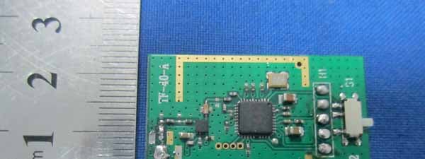
Y9XHPIRACING00002
Apr 05, 20123CH 2.4 GHz FHSS RADIO SYSTEM
Equipment Class
DSS - Part 15 Spread Spectrum Transmitter