Y9ZMT14H41303M Peltor Comtac VII Headset adapter
3M Company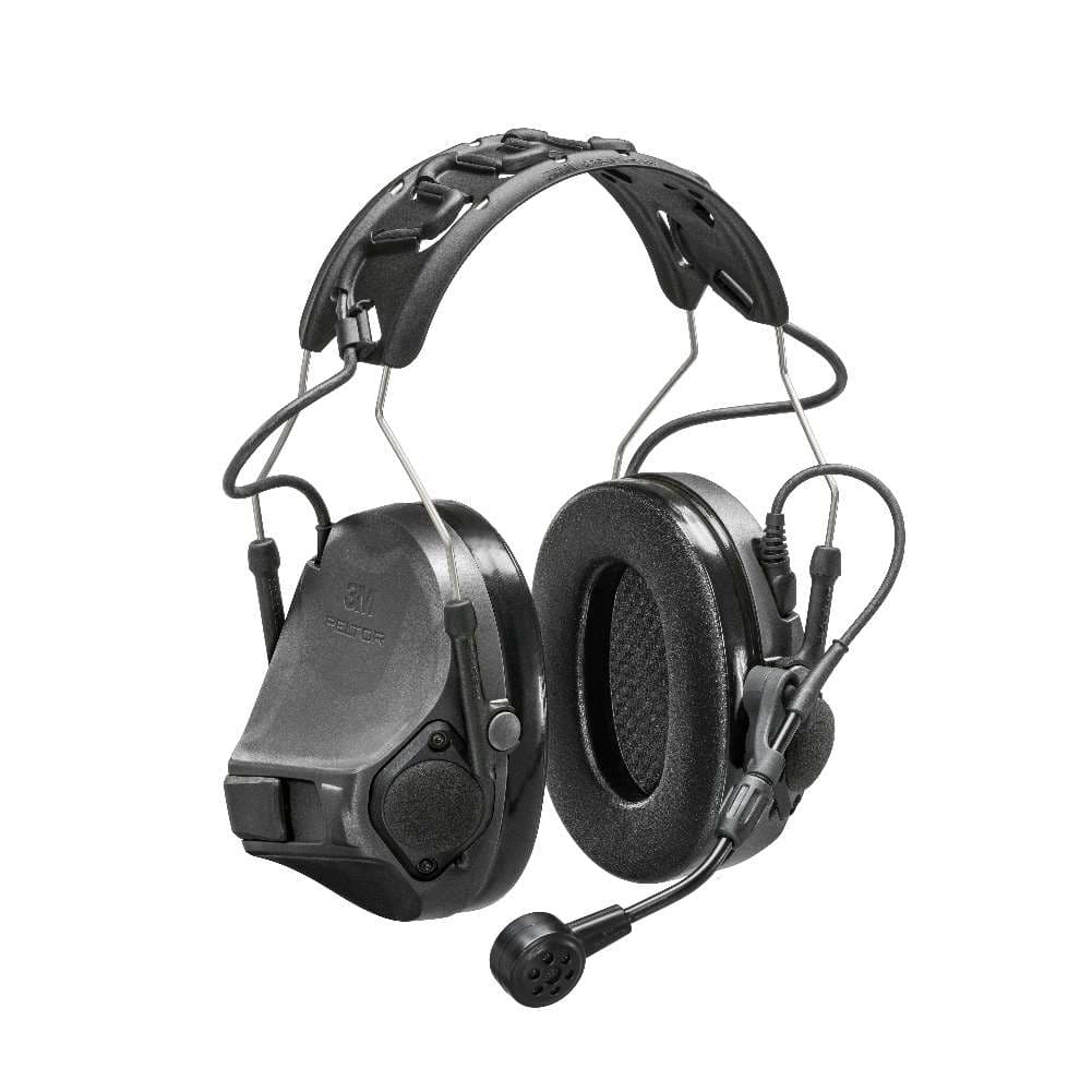
Click to zoom
Application Details
- Equipment Class
- DXT - Part 15 Low Power Transceiver, Rx Verified
- Date of Grant
- Jun 08, 2020
- Application Purpose
- Original Equipment
- Date of Application
- Jun 08, 2020
- Equipment Note
- 3M Peltor Comtac VII Headset adapter
- Frequency Range
- 915.50000000 - 915.50000000
- Company
- 3M Company
- Country
- United States
Documents & Files
Document Text
Text extracted from the exhibit documents filed with the FCC. Open a document above to read the original.
Users Manual
TM 3M Personal Safety Division 3M Center St. Paul, MN 55144-1000 FOR MORE INFORMATION In United States, contact: Website: www.3M.com/PELTOR Technical Assistance: 1-800-665-2942 [email protected] In Canada, contact: 1-855-484-3093 [email protected] For other 3M products: 1-800-3M-HELPS or 1-651-737-6501 FP3869REVB Please recycle. © 3M 2020. All rights reserved. 3M is a trademark of 3M Company, used under license in Canada. PELTOR is a trademark of 3M Company, used under license in Canada. Patent: www.3M.com/patent 3M PSD products are for occupational use only. PARA OBTENER MÁS INFORMACIÓN en los Estados Unidos: Internet: www.3M.com/PELTOR Información técnica: 1-800-665-2942 © 3M 2020. Todos los derechos reservados. 3M es una marca registrada de la Compañía 3M, utilizadas bajo licencia en Canadá. PELTOR es una marca registrada de la Compañía 3M, utilizada bajo licencia en Canadá. Los productos de la División de Protección Personal (PSD, por su sigla en inglés) de 3M son solo para uso profesional. 3M Personal Safety Division 3M Canada Company P.O. Box 5757, London, Ontario N6A 4T1 Division de la protection individuelle - 3M Company Canada 3M Canada, C.P. 5757 London (Ontario) N6A 4T1 FOR MORE INFORMATION/POUR OBTENIR DE PLUS AMPLES RENSEIGNEMENTS In Canada, contact/Au Canada, communiquer avec : Internet : www.3M.ca/safety Technical Assistance/Assistance technique : 1 800 267-4414 Centre d’aide à la clientèle/Customer Care Center : 1 800 364-3577 © 3M 2020. Tous droits réservés. 3M est une marque de commerce de 3M Company utilisées sous licence au Canada. PELTOR est une marque de commerce de 3M Company, utilisée sous licence au Canada. Les produits de la DPI de 3M sont destinés à une utilisation professionnelle seulement. TM ComTac™ VII LABORATORY ATTENUATION U.S. EPA specifies the NRR as the measure of hearing protector noise reduction. However, 3M makes no warranties as to the suitability of the NRR for this purpose. 3M strongly recommends personal fit testing of hearing protectors. Research suggests that users may receive less noise reduction than indicated by the attenuation label value(s) on the packaging due to variation in fit, fitting skill, and motivation of the user. Refer to applicable regulations for guidance on how to adjust attenuation label values. It is recommended that the NRR be reduced by 50% to better estimate typical protection. The attenuation rating (NRR) was obtained with the device powered off. STANDARD ANSI S3.19-1974 MT14H41A-300NA A:A Headband with foam cushion A:1 Frequency (Hz) (ƒ)125250500100020003150400063008000NRR CSA Class A:2 Mean attenuation (dB) (Mf) 14.019.427.932.331.739.744.540.141.0 22 A:3 Standard deviation (dB) (sf) 2.73.22.62.12.83.63.42.62.2 B MT14H41A-300NA with HY80 A:B Headband with gel cushion A:1 Frequency (Hz) (ƒ)125250500100020003150400063008000NRR CSA Class A:2 Mean attenuation (dB) (Mf) 14.918.527.134.534.139.842.140.940.1 23 A:3 Standard deviation (dB) (sf) 2.62.42.52.82.53.23.42.72.9 A MT14H41A-300NA A:C Helmet attachment with foam cushion on 3M Combat High Cut Ballistic Helmet C105HC A:1 Frequency (Hz) (ƒ)125250500100020003150400063008000NRR CSA Class A:2 Mean attenuation (dB) (Mf) 13.119.227.031.031.439.043.142.042.2 22 A:3 Standard deviation (dB) (sf) 2.92.72.22.02.82.93.23.03.3 B MT14H41A-300NA with HY80 A:D Helmet attachment with gel cushion on 3M Combat High Cut Ballistic Helmet C105HC A:1 Frequency (Hz) (ƒ)125250500100020003150400063008000NRR CSA Class A:2 Mean attenuation (dB) (Mf) 13.717.525.834.234.939.742.341.940.8 22 A:3 Standard deviation (dB) (sf) 2.82.52.22.12.32.83.82.92.3 A EN 1-16 ES 17-32 FR 33-48 3M™ PELTOR™ ComTac™ VII 1 3M™ PELTOR™ ComTac™ VII Headset MT14H41A-300NA (all product variants) 1. INTRODUCTION Congratulations and thank you for choosing 3M™ PELTOR™ protective communication solutions! Welcome to the next generation of protective communication. 1.1. INTENDED USE These 3M™ PELTOR™ headsets are intended to help protect against hazardous noise levels and loud sounds while allowing the user to hear the surroundings via the ambient/environmental microphones, listen to connected communication devices, and communicate face-to-face with integrated Natural Interaction Behavior (NIB) Technology in high levels of steady state noise. It is expected that all users read and understand the provided user instructions as well as be familiar with the use of this device. 2. SAFETY 2.1. IMPORTANT Please read, understand, and follow all safety information in these instructions prior to use. Retain these instructions for future reference. For additional information or any questions, contact 3M Technical Services. Refer to contact information listed on the last page of this manual. • This hearing protector helps reduce exposure to hazardous noise and other loud sounds. Misuse or failure to wear hearing protection at all times when exposed to hazardous noise may result in hearing loss or injury. For correct use, consult supervisor and User Instructions, or call 3M Technical Services. If your hearing seems dulled or you hear a ringing or buzzing during or after any noise exposure (including gunfire), or for any other reason you suspect a hearing problem, leave the noisy environment immediately and consult a medical professional and/or your supervisor. Failure to follow these instructions may result in serious injury or death: • Listening to audio communication may reduce your situational awareness and ability to hear warning signals. Stay alert and adjust the audio volume to the lowest acceptable level. • To reduce the risks associated with igniting an explosion, do not use this product in a potentially explosive atmosphere. Failure to follow these instructions may reduce the protection provided by the earmuff and may result in hearing loss: • U.S. EPA specifies the NRR as the measure of hearing protector noise reduction. However, 3M makes no warranties as to the suitability of the NRR for this purpose. 3M strongly rec…
Text truncated - open the document above for the full version.
Users Manual
14 7. Attach the microphone holder to the headband. 8. Turn the guide 90 degrees to locked position. 9. Turn the earcup without battery compartment according to the illustration and attach the guides. Note: Make sure the headband cable is placed outside the headband wire. 10. Turn the earcup 90 degrees to lock position. 11. Turn the other earcup according to the illustration and attach the guides to the earcup. 12. Turn the earcup 90 degrees to lock position. 13. Lift the headset in the headband cable to find the center of the headband cable. 14. Attach the center of headband cable to the clip by the arrow marking on the headband. ENEN 15 15. Attach the headband cable to the clips on the headband. 16. Connect the microphone cable to the left earcup. 12. STORAGE AND DISPOSAL 12.1. STORAGE • Clean the headset before storage. • Examine the headset for wear or damage. • Keep the headset in a clean and dry area within a temperature range of: -20°C/-4°F to 50°C/122°F. • Do not store the headset in direct sunlight. • During long term storage, remove the batteries from the battery compartment. 12.2. DISPOSAL • Obey national regulations. • To properly dispose of the battery, follow local solid waste disposal regulations. • Use the local recycling system for electronic equipment. 12.2.1. BATTERY DISPOSAL Many rechargeable batteries are required to be recycled by local, state/province, and national laws. To properly recycle/ dispose of the battery or battery pack, always follow local solid waste disposal regulations. EN 13. MAINTENANCE 13.1. TO CLEAN AND MAINTAIN THE HEADSET • Use a cloth wetted with soap and warm water to clean the outer shells, headband and ear cushions. • If the headset gets wet from rain or sweat, remove the ear cushions and foam liners, and allow to dry before reassembly. Refer to “13.2. To remove and replace the hygiene kit”. Note: This headset is designed to withstand brief, shallow water immersion, including saltwater. Following water exposure and immersion, the headset should be dried using the instructions listed above. Once dry, the user should perform a visual inspection and perform a functions test. If the visual inspection reveals salt crystal formation, the headset should be quickly rinsed with fresh water and allowed to dry. • Examine the ear cushions and foam liners regularly for damage. Ensure there are no cuts or tears and that the foam or gel cushions respond when compressed. After long use or improper storage, the ear cushions may become compressed and will no longer form a seal around the ear. A damaged ear cushion or foam liner must be replaced. Refer to “14. Accessories”. • Replace the foam liners and ear cushions a minimum of twice a year and as needed. Note: The environmental microphone windscreen serves a critical function in reducing wind noise that can interfere with environmental microphone performance. • Replace environmental/ambient microphone windscreens when torn or missing. 13.2. TO REMOVE AND REPLACE THE HYGIENE KIT 1. Hold the inner edge of the ear cushion and pull it straight out. 2. Remove the old ear cushion. 3. Remove the foam liner. 4. Put the new foam liner into the earcup. 5. Align the new ear cushion with the earcup. EN 16 6. Push the ear cushion into place. CAUTION: Make sure that the cushion cover is not pinched between the earcup and the ear cushion. 14. ACCESSORIES NameType M194/2 3M™ PELTOR™ Wind shield Kit for environmental mic 1086 SV/1 3M™ PELTOR™ Battery compartment cover AL8002/1 3M™ PELTOR™ Downlead cable ComTac™ VII AGM/1 3M™ PELTOR™ Headband ComTac™ VII A47/13M™ PELTOR™ Microphone guide MT71/1 3M™ PELTOR™ Boom microphone dynamic P3ADG47-F SV/2 3M™ PELTOR™ ARC rail attachment, 1 pair HY683M™ PELTOR™ Hygiene kit HY803M™ PELTOR™ Gel ring M171/2 3M™ PELTOR™ Wind protector for microphone, 2 pcs HYM1000 3M™ PELTOR™ Hygiene tape for boom microphone, black For more information about spare parts and accessories, please contact 3M Technical Services. Refer to contact information listed on the last page of this manual. 15. WARRANTY AND LIMITATION OF LIABILITY NOTE: The following statements do not apply in Australia and New Zealand. Consumers should rely on their statutory rights. 15.1. WARRANTY In the event any 3M Personal Safety Division product is found to be defective in material, workmanship, or not in conformity with any express warranty for a specific purpose, 3M’s only obligation and your exclusive remedy shall be at 3M’s option, to repair, replace or refund the purchase price of such parts or products upon timely notification of the issue by you and substantiation that the product has been stored, maintained and used in accordance with 3M’s written instructions. EXCEPT WHERE PROHIBITED BY LAW, THIS WARRANTY IS EXCLUSIVE AND IS IN LIEU OF ANY EXPRESS OR IMPLIED WARRANTY OF MERCHANTABILITY, FITNESS OR A PARTICULAR PURPOSE OR OTHER WARRANTY OF QUALITY, OR THOSE ARISING FROM A COURSE OF DEALING, CUSTOM OR USAGE OF TRADE, EXCEPT OF TITLE AND AGAINST PATENT INFRINGEMENT. 3M has no obligation under this warranty with respect to any product that has failed due to inadequate or improper storage, handling, or maintenance; failure to follow product instructions; or alteration or damage to the product caused by accident, neglect, or misuse. 14.2 LIMITATION OF LIABILITY EXCEPT WHERE PROHIBITED BY LAW, IN NO EVENT SHALL 3M BE LIABLE FOR ANY DIRECT, INDIRECT, SPECIAL, INCIDENTAL OR CONSEQUENTIAL LOSS OR DAMAGES (INCLUDING LOST PROFITS) ARISING FROM THIS PRODUCT, REGARDLESS OF THE LEGAL THEORY ASSERTED. THE REMEDIES SET FORTH HEREIN ARE EXCLUSIVE. 14.3 NO MODIFICATION Modifications to this device shall not be made without the written consent of 3M Company. Unauthorized modifications may void the warranty and the user’s authority to operate the device. NOTE: • Do not mix old and new batteries. • Do not mix alkaline, standard, or rechargeable batteries. • To properly dispose of the battery, follow local solid waste disposal regulations. • Only u…
Text truncated - open the document above for the full version.
Users Manual
34 FR 2.2. ATTENTION ! • Risque d’explosion si la pile est remplacée par une pile autre que celle prescrite. • Utilisez toujours des pièces de rechange 3M spécifiques au produit. L’utilisation de pièces de rechange non autorisées peut réduire la protection assurée par ce produit. 2.3. REMARQUE • Si la protection auditive est utilisée suivant les instructions de la notice, elle contribue à atténuer les nuisances sonores continues, comme les bruits industriels et les bruits de véhicules et d’avions, ainsi que les bruits très forts formés d’impulsions, comme ceux des armes à feu. Il est difficile de prédire la protection nécessaire et/ou la protection réelle lors de l’exposition à des bruits formés d’impulsions. Pour les coups de feu, les valeurs d’atténuation pourront varier en fonction du type d’arme à feu, du nombre de coups tirés, de l’utilisation et de l’entretien adéquat de la protection auditive ainsi que d’autres variables. Pour en savoir plus sur la protection auditive adaptée à des bruits impulsionnels, consulter le site www.3M.com/hearing. • Cette protection auditive comporte une entrée audio électrique. Il est recommandé à l’utilisateur de vérifier le bon fonctionnement du produit avant son utilisation. En cas de distorsion ou de tout autre dysfonctionnement, suivez les instructions du fabricant. • Au Canada, les utilisateurs de casque de chantier combiné avec un casque antibruit doivent se référer aux normes CSA Z94.1 relatives aux casques de protection industriels. • Lors du choix des accessoires pour équipement de protection respiratoire individuel, comme une protection auditive montée sur casque de sécurité, veuillez consulter l’étiquette d’homologation NIOSH ou le Centre d’assistance 3M pour connaître les configurations approuvées. 2.4. DÉCLARATIONS REQUISES PAR L’EPA DES ÉTATS-UNIS Un port incorrect de ce dispositif réduira son efficacité pour l’atténuation du bruit. Se reporter aux instructions d’utilisation ci-jointes, indiquant comment le porter correctement. Bien que les protections auditives puissent être recommandées pour la protection contre les effets nuisibles des bruits impulsionnels, le niveau de réduction du bruit (NRR) est basé sur l’atténuation du bruit continu et peut ne pas représenter de façon adéquate la protection contre les bruits impulsionnels comme des coups de feu. Le niveau de bruit qui pénètre dans l’oreille d’une personne, lorsque la protection auditive est portée comme indiqué, se rapproche étroitement de la différence entre le niveau de bruit environnement pondéré A et l’indice de niveau de réduction du bruit. Exemple 1. Le niveau de bruit environnemental tel que mesuré à l’oreille est de 92 dB(A). 2. Le NRR est de 22 décibels (dB). 3. Le niveau de bruit entrant dans l’oreille est à peu près de 70 dB(A). ATTENTION : Pour les environnements bruyants dominés par des fréquences inférieures à 500 Hz, c’est le niveau de bruit environnemental pondéré C qui doit être utilisé. 3. INFORMATIONS FCC ET IC Le présent appareil est conforme aux CNR d’Industrie Canada applicables aux appareils radio exempts de licence. L’exploitation est autorisée aux deux conditions suivantes: (1) l’appareil ne doit pas produire de brouillage ; (2) l’appareil doit accepter tout brouillage radioélectrique subi, même si le brouillage est susceptible d’en compromettre le fonctionnement. Remarque : Les changements ou modifications non expressément approuvés par le fabricant peuvent annuler les droits d’utilisation de l’appareil. 4. ATTÉNUATION EN LABORATOIRE 4.1. EXPLICATION DES TABLEAUX DES DONNÉES D’ATTÉNUATION A:ASerre-tête avec coussinet en mousse A:BSerre-tête avec coussinet en gel A:CAttache de casque avec coussinet en mousse A:DAttache de casque avec coussinet en gel A:1Fréquence (Hz) (ƒ) A:2Atténuation moyenne (dB) (Mf) A:3Écart type (dB) (sf) • Le niveau de sortie du circuit audio électrique de cette protection auditive peut dépasser le niveau limite d’exposition quotidienne. Réglez le volume audio au plus bas niveau acceptable. Les niveaux sonores de tout appareil externe connecté tel que les radios bidirectionnelles et les téléphones peuvent dépasser les niveaux de sécurité et doivent être limités de manière appropriée par l’utilisateur. Utilisez toujours des appareils externes au niveau sonore le plus bas possible pour la situation et limitez la durée pendant laquelle vous êtes exposé à des niveaux dangereux tels que déterminés par votre employeur et les réglementations applicables. En cas de diminution de l’audition ou si les oreilles sifflent ou bourdonnent pendant ou après l’exposition au bruit (y compris les coups de feu), ou tout autre symptôme, votre ouïe peut être menacée. Quittez l’environnement bruyant immédiatement et consultez un professionnel de la santé et/ou votre supérieur hiérarchique. • Si les exigences ci-dessus ne sont pas observées, la protection fournie par ce casque sera gravement compromise. 35 5. VU D’ENSEMBLE A F E B G H J I K L M N C D O Q R P A Serre-tête B Câble serre-tête C Coussinet D Rembourrage en mousse E Arceau de serre-tête F Guide G Connecteur microphone de communication H Microphone de communication I Bras de microphone de communication J Vis réglable K Microphone d’ambiance/de sons environnants L Bouton + M Bouton NIB N Bouton - O Coquille P Couvercle du compartiment des piles Q Guide pour le câble de serre-tête R Guide microphone de communication 6. EXPLICATION DES SYMBOLES Symbole de recyclage. Recyclez ce produit dans une station de recyclage pour équipements électriques et électroniques REMARQUE : D’autres symboles/autocollants peuvent apparaître sur le produit en raison des exigences de certification pour certaines zones commerciales. FR FR 36 7. POSITIONNEMENT DU CASQUE 7.1. POUR POSITIONNER LE SERRE-TÊTE 1. Positionnez les coquilles sur les oreilles. REMARQUE : Assurez-vous que le bandeau est en position en haut de votre tête. 2. Tenez la coquille et poussez l’arceau du serre-tête vers le haut ou vers le bas. 7.2. MONTAGE D…
Text truncated - open the document above for the full version.
Cover Letter(s)
Doc name Revision Page Creator Declaration Letter a.00 1 of 1 Pär Rundqvist 2020-05-27 Doc Type, Doc Description Scale Checked Declaration Letter N/A MT14H41A-300NA Approved Robert Karlsson 2020-05-27 © 3M Svenska AB Värnamo, Sweden Product Similar Declaration Letter To whom it may concern We, the undersigned hereby declare that the difference between the products model MT14H41A-300NA CY, MT14H41A-300NA GE, MT14H41A-300NA GN is only the color of the casing. CY is coyote brown; GE is grey and GN is green. Pär Rundqvist, Reg supervisor
Cover Letter(s)
24 Mars 2020 Equipment Autorisation Division Federal Communications Commission 7435 Oakland Mills Road Columbia, MD 21046 FCC ID: ___ Y9ZMT14H4130___ Product Name: ___ 3M Peltor Comtac VII Headset ___ Request for Confidentiality Pursuant to Sections 0.457 and 0.459 of the commission’s rules, we hereby request that the following documents be held confidential: Theory of Operation Component List (Bill of Materials) Block Diagram Schematics These materials contain trade secrets and proprietary information and are not customarily released to the public. The public disclosure of this information might be harmful to the company and provide unjustified benefits to our competitors. Dated this 24th Day of Mars 20 20 By: Pär Rundqvist Signature Printed Title: Regulatory Supervisor On behalf of: 3M Company Telephone: +46 370 694200
External Photos
COMTAC VII – FRONT SIDES COMTAC VII – BACK SIDE
ID Label/Location Info
MT14H41A-300NA CY MT14H41A-300NA GE MT14H41A-300NA GN Placingoflabels
Internal Photos
Internal photos Comtac VII K409 K417
RF Exposure Info
FCC ID: Y9ZMT14H4130 SAR Exclusion Justification Test exclusion thresholds for 100 MHz to 6 GHz at test separation distances ≤ 50 mm Guidance document reference: 447498 D01 General RF Exposure Guidance v05r02, page 11, paragraph 4.3.1(1). The 1-g and 10-g SAR test exclusion thresholds for 100 MHz to 6 GHz at test separation distances ≤ 50 mm are determined by: [(max. power of channel, including tune-up tolerance, mW)/(min. test separation distance, mm)] * [√f(GHz)] ≤ 3.0 for 1-g SAR and ≤ 7.5 for 10-g extremity SAR, where • f(GHz) is the RF channel transmit frequency in GHz • Power and distance are rounded to the nearest mW and mm before calculation • The result is rounded to one decimal place for comparison • 3.0 and 7.5 are referred to as the numeric thresholds in the step 2 below The test exclusions are applicable only when the minimum test separation distance is ≤ 50 mm and for transmission frequencies between 100 MHz and 6 GHz. When the minimum test separation distance is < 5 mm, a distance of 5 mm according to 5) in section 4.1 is applied to determine SAR test exclusion. SAR test exclusion analysis: Max. power of channel:1.9mW Min. separation distance:5mm Max. frequency:0.9155GHz [(Pwr/Dist)*√Freq.] = 0.4 The result of the above SAR threshold calculation demonstrates that the result is less than the 1-g numeric threshold of 3 and the 10-g numeric threshold of 7.5. Conclusion: The above analysis shows that the evaluated device qualifies for exemption from SAR testing. Signed: , Technical Manager 5/12/2020
Test Report
Report No. 383891-09-R01 Template version: C Nemko Norway Nemko AS, Instituttveien 6, P.O. Box 96 Kjeller, 2027 Kjeller, Norway TEL +47 22 96 03 30 FAX +47 22 96 05 50 EMAIL [email protected] ENTERPRISE NUMBER NO974404532 nemko.com/no Test Report Product Communications Headset with 915MHz Transceiver Name and address of the applicant 3M Svenska AB Box 2341, 331 02 Värnamo Sweden Name and address of the manufacturer 3M Svenska AB Box 2341, 331 02 Värnamo Sweden Model MT14H41A-300NA Rating 3.0V DC (2x AAA cells, Alkaline Batteries) Trademark Comtac VII Serial number NI-B-4 Additional information NIB, NFMI Tested according to FCC Part 15.249 Operation within the bands 902-928 MHz, 2400-2483.5 MHz, 5725-5875 MHz, and 24.0-24.25 GHz Industry Canada RSS-210, Issue 10, Annex B10 Bands 902-928 MHz, 2400-2483.5 MHz and 5725-5875 MHz Order number 383891 Tested in period 2020-02-25 Issue date 2020-06-09 Name and address of the testing laboratory Instituttveien 6 Kjeller, Norway www.nemko.com CAB Number: FCC: NO0001 ISED: NO0470 TEL: +47 22 96 03 30 FAX: +47 22 96 05 50 An accredited technical test executed under the Norwegian accreditation scheme Prepared by [Frode Sveinsen] Approved by [G.Suhanthakumar] This report shall not be reproduced except in full without the written approval of Nemko. Opinions and interpretations expressed within this report are not part of the current accreditation. This report was originally distributed electronically with digital signatures. For more information contact Nemko. TEST REPORT FCC Part 15.249 Report no.: 383891-09-R01 FCC ID: Y9ZMT14H4130 IC: 4406A-MT14H4130 Nemko Norway, Instituttveien 6, Kjeller, Norway Page 2 (20) CONTENTS 1 INFORMATION ......................................................................................................................... 3 1.1 Test Item .................................................................................................................................... 3 1.2 Normal test condition ................................................................................................................. 4 1.3 Test Engineer(s) ........................................................................................................................ 4 1.4 Antenna Requirement ................................................................................................................ 4 1.5 Worst-Case Configuration and Mode ......................................................................................... 4 1.6 Comments ................................................................................................................................. 4 2 TEST REPORT SUMMARY ...................................................................................................... 5 2.1 General ...................................................................................................................................... 5 2.2 Test Summary ........................................................................................................................... 6 3 TEST RESULTS ........................................................................................................................ 7 3.1 Occupied (Emission) Bandwidth ................................................................................................ 7 3.2 Field Strength of Fundamental................................................................................................... 9 3.3 Restricted Bands of operation.................................................................................................. 11 3.4 Radiated Emission, 30 – 1000 MHz ......................................................................................... 12 3.5 Radiated Emissions, 1-10 GHz ................................................................................................ 15 4 Measurement Uncertainty ..................................................................................................... 18 5 LIST OF TEST EQUIPMENT................................................................................................... 19 6 BLOCK DIAGRAM .................................................................................................................. 20 6.1 Power Line Conducted Emission ............................................................................................. 20 6.2 Test Site Radiated Emission .................................................................................................... 20 TEST REPORT FCC Part 15.249 Report no.: 383891-09-R01 FCC ID: Y9ZMT14H4130 IC: 4406A-MT14H4130 Nemko Norway, Instituttveien 6, Kjeller, Norway Page 3 (20) 1 INFORMATION 1.1 Test Item Name Comtac VII FCC ID Y9ZMT14H4130 ISED ID 4406A-MT14H4130 Model/version MT14H41A-300NA Serial number NI-B-4 Hardware identity and/or version K409 AVE Software identity and/or version K409-sku 3.3.0 Frequency Range 915.500 MHz Channel Spacing N/A Number of Channels 1 Operating Modes Digital Modulation Type of Modulation FSK User Frequency Adjustment None Type of Power Supply Primary Batteries (2x AAA alkaline cells) Antenna Connector None (Integral Antenna) Number of Antennas 1 Desktop Charger N/A Interfaces Proprietary connector for connecting to SCU300 Description of Test Item This is a personal communications headset with 915MHz NIB transceiver for communication with other COMTAC VII headsets nearby and 10MHz NFMI transceiver for communication with the SCU300 System Control Unit. TEST REPORT FCC Part 15.249 Report no.: 383891-09-R01 FCC ID: Y9ZMT14H4130 IC: 4406A-MT14H4130 Nemko Norway, Instituttveien 6, Kjeller, Norway Page 4 (20) 1.2 Normal test condition Temperature: 20 - 24 ° C Relative humidity: 20 - 50 % Normal test voltage: 3.0V DC (Nominal Voltage) The values are the limit registered during the test period. 1.3 Test Engineer(s) Frode Sveinsen 1.4 Antenna Requirement Is the antenna detachable? Yes No If detachable, is the antenna connect…
Text truncated - open the document above for the full version.
Test Report
Report No. 383891-11-R00 Template version: C Nemko Norway Nemko AS, Instituttveien 6, P.O. Box 96 Kjeller, 2027 Kjeller, Norway TEL +47 22 96 03 30 FAX +47 22 96 05 50 EMAIL [email protected] ENTERPRISE NUMBER NO974404532 nemko.com/no Test Report Product Headset Name and address of the applicant 3M Svenska AB Box 2341, 331 02 Värnamo Sweden Name and address of the manufacturer 3M Svenska AB Box 2341, 331 02 Värnamo Sweden Model MT14H41A-300NA Rating 3.0V DC (2x AAA cells, Alkaline Batteries) Trademark Comtac VII Serial number NI-B-2 Additional information NMI, NFMI Tested according to FCC Part 15.209 Operation within the general radiated emission limits Industry Canada RSS-GEN, Issue 5 Operation within the general radiated emission limits Order number 383891 Tested in period 2020-02-28 Issue date 2020-04-28 Name and address of the testing laboratory Instituttveien 6 Kjeller, Norway www.nemko.com CAB Number: FCC: NO0001 ISED: NO0470 TEL: +47 22 96 03 30 FAX: +47 22 96 05 50 An accredited technical test executed under the Norwegian accreditation scheme Prepared by [Frode Sveinsen] Approved by [G.Suhanthakumar] This report shall not be reproduced except in full without the written approval of Nemko. Opinions and interpretations expressed within this report are not part of the current accreditation. This report was originally distributed electronically with digital signatures. For more information contact Nemko. TEST REPORT FCC Part 15.209 Report no.: 383891-11-R00 FCC ID: Y9ZMT14H4130 IC: 4406A-MT14H4130 Nemko Norway, Instituttveien 6, Kjeller, Norway Page 2 (18) CONTENTS 1 INFORMATION ......................................................................................................................... 3 1.1 Test Item .................................................................................................................................... 3 1.2 Normal test condition ................................................................................................................. 4 1.3 Test Engineer(s) ........................................................................................................................ 4 1.4 Antenna Requirement ................................................................................................................ 4 1.5 Worst-Case Configuration and Mode ......................................................................................... 4 1.6 Comments ................................................................................................................................. 4 2 TEST REPORT SUMMARY ...................................................................................................... 5 2.1 General ...................................................................................................................................... 5 2.2 Test Summary .............................................................…
Text truncated - open the document above for the full version.
Contact Information
Applicant
Yuriy Litvinov(Lead EMC Engineer)
Test Firm
Nemko Scandinavia ASTor Erik Pedersen
[email protected]+4798228176
Technical Specifications
| # | Rule Parts | Frequency Range | Power Output |
|---|---|---|---|
| 2 | 15C | 915.5 MHz - 915.5 MHz | - |
Other Applications from 3M Company
Y9ZFL8000WS7
Jul 17, 20263M Peltor Multi-Comm Push-To-Talk Adapter
Equipment Class
DTS - Digital Transmission SystemY9ZMT14H419
Apr 16, 2026Hearing protection with two-way radio headset
Equipment Class
DXX - Part 15 Low Power Communication Device TransmitterY9ZFL61007WS7
Sep 16, 2024WS ADAPTER G3
Equipment Class
DSS - Part 15 Spread Spectrum TransmitterY9ZMRX21A1WS7
Sep 15, 2024WS ALERT XPV Headset
Equipment Class
DSS - Part 15 Spread Spectrum Transmitter
Y9ZMRX21AWS6
Apr 13, 2022WS Alert X, XP, XPI and XPV
Equipment Class
JBP - Part 15 Class B Computing Device Peripheral