Y9ZMT401050Lite-Com Pro II
3M Company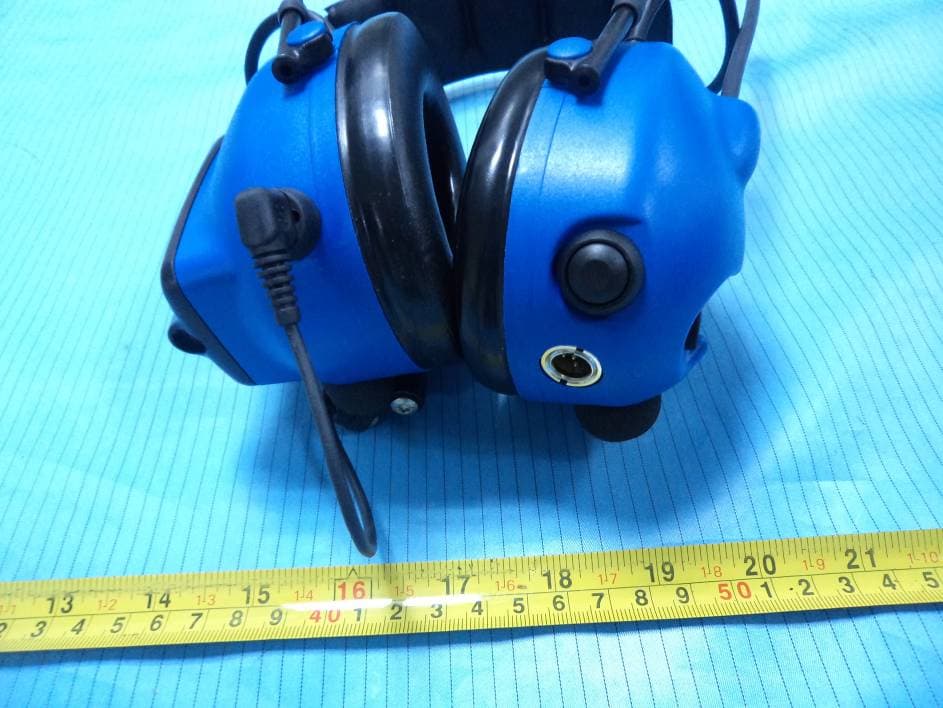
Click to zoom
Application Details
- Equipment Class
- FRE - Part 95 Family Radio Ear Held Transmitter
- Date of Grant
- Aug 27, 2012
- Application Purpose
- Original Equipment
- Date of Application
- Aug 27, 2012
- Equipment Note
- Lite-Com Pro II
- Frequency Range
- 467.56250000 - 467.71250000
- Company
- 3M Company
- Country
- United States
Documents & Files
Document Text
Text extracted from the exhibit documents filed with the FCC. Open a document above to read the original.
Users Manual
CE:PMR 11003072169 FP3694 Rev. a Quick reference guide Key Function MODE Switches the Lite-Com Pro II on and off. Choose between the functions in the menu. UP (+) Increases the level of the selected function. DOWN (–) Decreases the level of the selected function. PTT Transmits with the Lite-Com Pro II. E) Attenuation (with head band) Frequency (Hz)1252505001000200040008000HMLSNR Mean attenuation (dB) 14.723.430.734.634.536.937.3 St. dev. (dB)3.94.63.23.43.12.74.233 dB27 dB19 dB30 dB APValue (84%)10.818.827.431.231.434.233.1 Attenuation (with neck band) Frequency (Hz)1252505001000200040008000HMLSNR Mean attenuation (dB) 15.523.331.235.635.036.540.9 St. dev. (dB)2.62.32.03.23.43.43.333 dB29 dB21 dB31 dB APValue (84%)13.021.029.232.431.633.237.6 Attenuation (with helmet attachment) Frequency (Hz)1252505001000200040008000HMLSNR Mean attenuation (dB) 16.222.931.735.634.537.740.0 St. dev. (dB)3.22.22.02.93.03.93.333 dB29 dB21 dB31 dB APValue (84%)13.020.729.732.731.533.836.8 MT53H7F470-50 MT53H7B470-50 MT53H7P3E470-50 403 – 470 MHz MT7H7F4010-EU-50 MT7H7B4010-EU-50 MT7H7P3E4010-EU-50 Peltor ™ Lite-Com ™ Pro II The Sound Solution Mean attenuation (dB) = Average attenuating characteristics at given frequency St. dev. (dB) = Standard deviation at given frequency APV (dB) = Assumed Protection Value. Average attenuating characteristics minus standard deviation at given frequency. H = Average attenuation characteristics in the higher frquency spectrum M = Average attenuation characteristics in the mid range frequency spectrum L = Average attenuation characteristics in the higher frequency spectrum SNR = Single Number Rating 3M Occupational Health & Environmental Safety Division 3M Svenska AB, Box 2341 SE-331 02 Värnamo Sweden Phone: +46 (0) 370 65 65 65 Fax: +46 (0) 370 65 65 99 Email: [email protected] Internet: www.3M.com/Peltorcomms © 3M 2012. All rights reserved. 3M™ Peltor™ Lite-Com™ Pro is made in Sweden by 3M Svenska AB, SE-331 02, Värnamo, Sweden. 3M, Peltor and Peltor Lite-Com are trademarks of 3M Corporation, St. Paul, MN 55144-1000, USA Please recycle. Printed in Sweden. Peltor Lite-Com Pro II Product Range MT7H7F4010-EU-50 with headband MT7H7B4010-EU-50 with neckband MT7H7P3E4010-EU-50 with helmet attachment for Peltor G22 and G3000 hardhats. (A rear plate is also included for helmet attachments for the Peltor G2000 hardhat.) Technical Data Frequency range: Operation mode: Simplex Channels: Max. 30 Channel raster: Channel separation: Modulation: (FM) FM (16K0F3E / 8K50F3E) Microphone type: Electret (MT53) or dynamic (MT7) Receiver sensibility: Typical -122 dBm Selective squelch: Programmable (and supports CTCSS and DCS) Output power: 200 / 20 / 10 mW ERP Range: Outdoors up to 3 km depending on conditions Power consumption: Stand-by: ca 55 mA Receiving: ca 65 mA Transmission: Low power: ca 100 mA Medium power: ca 115 mA High power: ca 200 mA Operating time at conditions 10/10/80 TX/RX/Standby at 20°C: Hi output power: ca 14 hours Mid output power: ca 16 hours Low output power: ca 17 hours Operating temperature: -20°C to +55°C Storage temperature: -40°C to +55°C Weights including ACK08 battery: MT7H7F4010-**-50: 540 g MT7H7B4010-**-50: 500 g MT7H7P3E4010-**-50: 540 g ACK08 technical information Charging time: approx. 10-12 hours (no visible charging indicators for ACK08) Capacity: 3,7 V, 1350 mA, 5 Wh Charging cable: AL2AH (fused 200mA) After charging cycle is finished charger automatically turns into maintenance charging mode. ACK08 must be charged with AL2AH connected to a certified 5V SELV power supply such as 3M, Peltor battery charger FR08. Power supply must be able to deliver a minimum of 200 mA. FCC:462.5625MHz~467.7125MHz, FCC/IC: 12.5 kHz CE: 12.5 kHz/ 25 kHz FCC/IC: 2.5 kHz CE: 2.5 kHz/ 5kHz 406.1 - 430,440 - 470MHz,LPD:433.05 - 434.79 MHz(Note:LPD only used in Europe) (Fig. H) (Fig. A) 1 3 2 (J) 1 3 2 (K) D:1) D:2) Auxiliary connection RMS Voltage U (mV) Mean sound Pressure (dBA) STD sound Pressure (dBA) 363.43.0 567.43.3 871.23.1 1475.53.1 2580.23.1 4084.02.7 x 2x 8x4x 2 4 6 8 0 16x Average level / electronic input signal x = 22 mV Squelch Tones and Codes CTCSS (Continuous Tone Coded Squelch System) 1. 67.08. 88.515. 110.922. 141.329. 179.936. 233.6 2. 71.99. 91.516. 114.823. 146.230. 186.237. 241.8 3. 74.410. 94.817. 118.824. 151.431. 192.838. 250.3 4. 77.011. 97.418. 123.025. 156.732. 203.5 5. 79.712. 100.019. 127.326. 162.233. 210.7 6. 82.513. 103.520. 131.827. 167.934. 218.1 7. 85.414. 107.221. 136.528. 173.835. 225.7 DCS (Digitally Coded Squelch) 39. 02353. 11467. 17481. 31595. 445109. 631 40. 02554. 11568. 20582. 33196. 464110. 632 41. 02655. 11669. 22383. 34397. 465111. 654 42. 03156. 12570. 22684. 34698. 466112. 662 43. 03257. 13171. 24385. 35199. 503113. 664 44. 04358. 13272. 24486. 364100. 506114. 703 45. 04759. 13473. 24587. 356101. 516115. 712 46. 05160. 14374. 25188. 371102. 532116. 723 47. 05461. 15275. 26189. 411103. 546117. 731 48. 06562. 15576. 26390. 412104. 565118. 732 49. 07163. 15677. 26591. 413105. 606119. 734 50. 07264. 16278. 27192. 423106. 612120. 743 51. 07365. 16579. 30693. 431107. 624121. 754 52. 07466. 17280. 31194. 432108. 627 4 1 3M ™ Peltor ™ Lite-Com ™ Pro II GB, IE, ZA, AE, AU, NZ2-11 FR, CH, BE DE, CH, AT IT, CH ES NL, BE SE DK NO FI PT GR PL HU CZ SK SI IL EE LV LT RO RU, BY, AZ UA HR BG RS TR KZ Appendix A Declaration of Conformity ATEX Certificate IECEX Certificate range of up to approximately 3 km outdoors. Low power setting gives a range of up to approximately 1 km. The highest power setting gives a 2 PELTOR Lite-Com Pro II Programmable wireless communication headset with surround sound listening feature. The Peltor Lite-Com Pro II offers reliable, efficient wireless communication between two or more individuals, even in noisy environments. The product is intrinsically safe and approved for use in potentially explosive environments (I.S. approved.) Read these instructions carefully before use and save for future reference. FUNC…
Text truncated - open the document above for the full version.
Attestation Statements
Attestation :
Cover Letter(s)
3M Peltor Add: 5457 West 79th Street, Indianapolis, IN 46268, United States Tel: (317)692 3163 Fax: (317)692 6604 FCC Confidential Authorization Date: 2012-04-27 FEDERAL COMMUNICATIONS COMMISSIONS Authorization and Evaluation Division 7435 Oakland Mills Road Columbia, MD 21046 Confidentiality Request regarding application for certification of FCC ID: Y9ZMT401050 Pursuant to Sections 0.457 and 0.459 of the Commission’s Rules, we hereby request confidential treatment of information accompanying this application as outlined below: Detailed Circuit Schematics of EUT--- (Long term) Block Diagram--- (Long term) Circuit Description--- (Long term) The above materials contain trade secrets and proprietary information not customarily released to the public. The public disclosure of these materials may be harmful to the applicant and provide unjustified benefits to its competitors. The applicant understands that pursuant to Section 0.457 of the Rules, disclosure of this application and all accompanying documentation will not be made before the date of the Grant for this application. Sincerely Yours, Signature: Timothy N.Allen Product Portfolio Manager North America
External Photos
EXHIBIT B - EUT EXTERNAL PHOTOGRAPHS EUT View 1 EUT View 2 EUT– Bottom View
ID Label/Location Info
EXHIBIT A - FCC ID LABELING AND LOCATION FCC ID Labeling Suggested FCC ID Location Label Location
Internal Photos
EXHIBIT C - EUT INTERNAL PHOTOGRAPHS EUT- Battery off View EUT- Cover off View EUT- Internal View 1 EUT- Internal View 2 Antenna EUT- Main Board Top View EUT- Main Board Top Shielding off View EUT- Main Board Bottom View EUT- Main Board Bottom Shielding View EUT- Power Board Top View EUT- Power Board Top Shielding off View EUT- Power Board Bottom View EUT- Antenna Connected Board View EUT- Battery View
Test Report
Note: This test report is prepared for the customer shown above and for the device described herein. It may not be duplicated or used in part without prior written consent from Bay Area Compliance Laboratories Corp. This report must not be used by the customer to claim product certification, approval, or endorsement by NVLAP*, or any agency of the Federal Government. * This report contains data that are not covered by the NVLAP accreditation and are marked with an asterisk “★” (Rev.2) FCC PART 95 EMI MEASUREMENT AND TEST REPORT For 3M Peltor 5457 West 79th Street, Indianapolis, IN 46268, United States FCC ID: Y9ZMT401050 Report Type: Original Report Product Type: Programmable 2-way transceiver headset Test Engineer: Jim Huang Report Number: R1DG120426006-00 Report Date: 2012-05-23 Reviewed By: Alvin Huang RF Leader Test Laboratory: Bay Area Compliance Laboratories Corp. (Shenzhen) 6/F, the 3rd Phase of WanLi Industrial Building, ShiHua Road, FuTian Free Trade Zone Shenzhen, Guangdong, China Tel: +86-755-33320018 Fax: +86-755-33320008 www.baclcorp.com.cn Bay Area Compliance Laboratories Corp. (Shenzhen) Report No.: R1DG120426006-00 FCC Part 95 Page 2 of 24 TABLE OF CONTENTS GENERAL INFORMATION.......................................................................................................................................3 PRODUCT DESCRIPTION FOR EQUIPMENT UNDER TEST (EUT) ....................................................................................3 OBJECTIVE...................................................................................................................................................................3 RELATED SUBMITTAL(S)/GRANT(S).............................................................................................................................3 TEST METHODOLOGY..................................................................................................................................................3 TEST FACILITY.............................................................................................................................................................3 SYSTEM TEST CONFIGURATION ..........................................................................................................................5 DESCRIPTION OF TEST CONFIGURATION......................................................................................................................5 EQUIPMENT MODIFICATIONS.......................................................................................................................................5 BLOCK DIAGRAM OF TEST SETUP................................................................................................................................5 SUMMARY OF TEST RESULTS ...............................................................................................................................6 FCC §2.1093 - RF EXPOSURE INFORMATION .....................................................................................................7 APPLICABLE STANDARD..............................................................................................................................................7 RESULT........................................................................................................................................................................7 FCC §2.1046, §95.639(a) & §95.639(d) - RF OUTPUT POWER ..............................................................................8 APPLICABLE STANDARD..............................................................................................................................................8 TEST PROCEDURE........................................................................................................................................................8 TEST EQUIPMENT LIST AND DETAILS...........................................................................................................................8 TEST DATA..................................................................................................................................................................8 FCC §2.1047 & §95.637(a) - MODULATION CHARACTERISTIC .....................................................................10 APPLICABLE STANDARD............................................................................................................................................10 TEST EQUIPMENT LIST AND DETAILS.........................................................................................................................10 TEST PROCEDURE......................................................................................................................................................10 TEST DATA................................................................................................................................................................10 FCC §2.1049 & §95.633(a) (c) - OCCUPIED BANDWIDTH AND EMISSION MASK.......................................17 APPLICABLE STANDARD............................................................................................................................................17 TEST PROCEDURE......................................................................................................................................................17 TEST EQUIPMENT LIST AND DETAILS.........................................................................................................................17 TEST DATA................................................................................................................................................................17 FCC §2.1053 & §95.635(b) (7) - RADIATED SPURIOUS EMISSION ..................................................................20 APPLICABLE STANDARD.............................................................................................................…
Text truncated - open the document above for the full version.
Test Setup Photos
EXHIBIT D - TEST SETUP PHOTOGRAPHS Radiated Emission - (Below 1GHz) Radiated Emission - (Above 1GHz) Frequency Stability View
Contact Information
Applicant
Yuriy Litvinov(Lead EMC Engineer)
Test Firm
Bay Area Compliance Laboratory Corp. (Shenzhen)John Chan
Technical Specifications
| # | Rule Parts | Frequency Range | Power Output | Emission | Tolerance |
|---|---|---|---|---|---|
| 3 | 95B | 467.5625 MHz - 467.7125 MHz | 219.00 mW | 6K70F3E | 0.8 ppm |
Other Applications from 3M Company
Y9ZFL8000WS7
Jul 17, 20263M Peltor Multi-Comm Push-To-Talk Adapter
Equipment Class
DTS - Digital Transmission SystemY9ZMT14H419
Apr 16, 2026Hearing protection with two-way radio headset
Equipment Class
DXX - Part 15 Low Power Communication Device TransmitterY9ZFL61007WS7
Sep 16, 2024WS ADAPTER G3
Equipment Class
DSS - Part 15 Spread Spectrum TransmitterY9ZMRX21A1WS7
Sep 15, 2024WS ALERT XPV Headset
Equipment Class
DSS - Part 15 Spread Spectrum Transmitter
Y9ZMRX21AWS6
Apr 13, 2022WS Alert X, XP, XPI and XPV
Equipment Class
JBP - Part 15 Class B Computing Device Peripheral