YBGGOODCOM-FW-101GSM Fixed Wireless Terminal
XIAMEN GOODCOM TECHNOLOGY CO., LTD.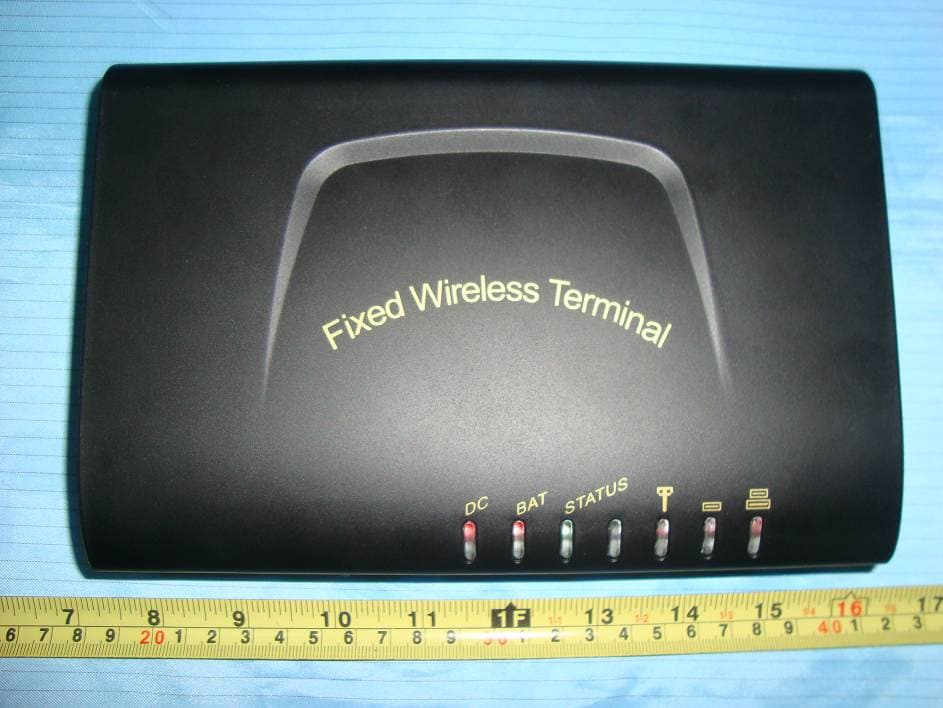
Click to zoom
Application Details
- Equipment Class
- PCB - PCS Licensed Transmitter
- Date of Grant
- May 04, 2010
- Application Purpose
- Original Equipment
- Date of Application
- May 04, 2010
- Equipment Note
- GSM Fixed Wireless Terminal
- Frequency Range
- 1850.20000000 - 1909.80000000
- Country
- China
Documents & Files
Document Text
Text extracted from the exhibit documents filed with the FCC. Open a document above to read the original.
Users Manual
GSM Fixed Wireless Te r m i n a l User Manual V3.0 1 Contents 1. Summary ........................................................................... 2 2. Main function.................................................................... 3 3. Interference ....................................................................... 3 4.Notice List .......................................................................... 4 5. Installation ........................................................................ 5 5.1.Interface........................................................................................................................................ 5 5.2. Indicator lights............................................................................................................................. 5 5.3. Signification of Indicator lights ................................................................................................... 6 5.4. Installation ................................................................................................................................... 7 6. How to use ......................................................................... 8 6.1. Making Calls ............................................................................................................................... 8 6.2. Answering a call .......................................................................................................................... 9 7. Other function................................................................... 9 8. Technical Specifications ................................................. 11 9. Environment standard ................................................... 11 10. Problem and Solution ................................................... 12 2 Welcome to use the GSM Fixed Wireless Terminal. Please read this simple guidance. Further detailed information is given in this manual. 1. Summary GSM Fixed Wireless Terminal is a mobile terminal for telecommunication operators to develop fixed telephone services. It takes the advantages of the wide coverage of mobile communication network and convenient installation to meet the fast increasing requirement of users. The product is particularly suitable for telecommunication operators to entry the common fixed telephone market. With easy installation and high efficiency, it can be widely applied in 1. Various enterprises 2. Institutes 3. Movable carriers 4. Places of interest/ scenic spots 5. Large exhibitions 6. Consulting meetings 7. Others It is used where telephone lines are unavailable or very limited. The installation is easy and rapid and can be put into use as soon as within mobile network, while can solve problems of line deficiency and temporary telecommunication. It can be connected to common phones via GSM network, providing a service compared favorably to fixed phones, and producing a 3 communication effect similar to that of fixed phones. This Wireless Terminal is mainly applied within the coverage of GSM cellular network. 2. Main function GSM cellular network outgoing. GSM cellular network incoming. DTMF Caller ID. Support secondary dial. Send polarity reversal signal for billing meter while connection. Sending 12/16KHz pulse for billing meter while connection is also compatible. Data Interface, perform wireless GPRS cooperate with PC. (Optional) Rechargeable battery, keep conversation for at least 3 hour when out of mains supply. (Optional) 3. Interference All wireless devices may get interference which could affect performance. Please make sure that your device is in service, and pay attention to conditions as follows. 4 Topic Description Hospital Follow any regulations or rules. Switch the device off near medical equipment. Aircraft Wireless devices can cause interference. Using them on aircraft is illegal. Fuel Don’t use the device at a refueling point. Don’t use near fuel or chemicals Blasting Don’t use the device where blasting is in progress. Observe restrictions, and follow any regulations or rules. Children Keep your device in a safe place and keep it in out of small children’s reach. Children could hurt themselves or others and they may damage the device. 4.Notice List Description 1 Don’t attempt to repair the device by yourself. Only qualified service personnel could install or repair the device. 2 Do not tie the antenna with the telephone line during use. Otherwise it could cause interference and affect connection quality. 3 Please install the antenna 1 meter faraway from the device or other sensitive electron device. If the antenna is damaged, do not use it any more. You can contact the franchiser to repair it. 4 Do not use unqualified antenna or try to modify any part of the device. 5 To avoid noise interference, use an anti-EMI phone if possible. 6 If the device installed rechargeable battery, please recharge for at least 24 hours before the first use. If the device is in “Turn Off” state, it do not recharge to the battery. 7 Please use the device stand to the manual. 8 Use the provided USB data cable for connecting internet. (Optional) 5 5. Installation 5.1.Interface The back of the device as below: 5.2. Indicator lights There are 7 indicator lights in the terminal device. From left to right in turn, it is: 1. Power indicator lights (Adapters) 2. Power indicator lights (Battery) 3. Status indicator lights 4. No use (reserve) 6 5. Signal Strength 1 6. Signal Strength 2 7. Signal Strength 3 5.3. Signification of Indicator lights Indicator Light Description 1 Signal Strength 1 flash one times Signal Strength 2 flash one times Signal Strength 3 flash one times Startup 2 Power Light constantly on Power normal 3 Power Light constantly off Power un-normal 4 Power indicator lights (Adapters) Off Power indicator lights (Battery) On Power supply by battery 5 When not in conversation: Signal Strength 1 flash Signal Strength 2 flash Signal Strength 3 flash No SIM card or …
Text truncated - open the document above for the full version.
Cover Letter(s)
XIAMEN GOODCOM TECHNOLOGY CO.,LTD. Cell B,9/FL,Office Bldg II,151 Yuehua Road,Huli District,Xiamen,China Tel: 86-592-6022520 Fax: 86-592-6022530 Product Similarity Declaration To Whom It May Concern, We, XIAMEN GOODCOM TECHNOLOGY CO.,LTD., hereby declare that our GSM Fixed Wireless Terminal, Model Number: GW1000G、GW1000BL、GT3000N、 GT5000S、GT1000N、GW1000B、GTP60 is electrically identical with the Model Number: GW5000 that was certified by BACL. They are the same circuit and PCB layout except color appearance. Please contact me if you have any question. Signature: Print Name: Jay Xiong Title: Vice-President Date: 2010-04-10
Cover Letter(s)
fcc confidential authorization (1653x2344x24b jpeg)
External Photos
EXHIBIT B - EUT EXTERNAL PHOTOGRAPHS EUT – Full View EUT – Top View EUT – Bottom View EUT – Side View
ID Label/Location Info
EXHIBIT A - FCC ID LABELING AND LOCATION FCC ID Label FCC ID Label Location Label here The label shown shall be permanently affixed at a conspicuous location on the device and be readily visible to the user at the time purchase (Labeling requirements per 2.925)
Internal Photos
EXHIBIT C - EUT INTERNAL PHOTOGRAPHS EUT – Cover off View EUT – Main Board Top Components View EUT – Main Board Bottom Components View EUT – Adapter View EUT – Battery View EUT – Antenna View
RF Exposure Info
Xiamnen Goodcom Technology Co., Ltd. FCC ID: YBGGOODCOM-FW-101 Report No.: RXM10033151 Page 9 of 37 FCC Part 22H/24E Test Report FCC §1.1307 & §2.1091 - RF EXPOSURE Applicable Standard According to §1.1307(b)(1), systems operating under the provisions of this section shall be operated in a manner that ensures that the public is not exposed to radio frequency energy level in excess of the Commission’s guidelines. According to §1.1310 and §2.1091 RF exposure is calculated. Limits for General Population/Uncontrolled Exposure Frequency Range (MHz) Electric Field Strength (V/m) Magnetic Field Strength (A/m) Power Density (mW/cm 2 ) Averaging Time (minutes) 0.3-1.34 614 1.63 *(100) 30 1.34-30 824/f 2.19/f *(180/f 2 ) 30 30-300 27.5 0.073 0.2 30 300-1500 / / f/1500 30 1500-100,000 / / 1.0 30 f = frequency in MHz * = Plane-wave equivalent power density Test Data Predication of MPE limit at a given distance Where: S = power density (in appropriate units, e.g. mW/cm2) P = output power to antenna G= Antenna Gain (numeral) R = distance to the center of radiation of the antenna (appropriate units, e.g., cm) Table: Maximum Permissible Exposure (MPE) Calculations Max Conducted Power Band Frequency (MHz) Ant. Gain (dBi) (dBm) (mW) Duty Cycle Evaluation Distance (cm) Power Density (mW/cm 2 ) MPE Limit (mW/cm 2 ) GSM 850 (2 Slots) 848.8 0.5 32.45 1757.92 25% 20 0.098 0.566 PCS 1900 (2 Slots) 1850.2 1.0 29.06 805.38 25% 20 0.050 1.0 Result: EUT meets the MPE limits at 20 cm distance as specified in section 2.1091 of the FCC rules. An appropriate RF exposure compliance statement will be placed in the User’s Guide.
Test Report
Note: This test report is prepared for the customer shown above and for the device described herein. It may not be duplicated or used in part without prior written consent from Bay Area Compliance Laboratories Corp. This report must not be used by the customer to claim product certification, approval, or endorsement by NVLAP*, NIST, or any agency of the Federal Government. * This report may contain data that are not covered by the NVLAP accreditation and are marked with an asterisk “*” (Rev.2) FCC PART 22H, 24E MEASUREMENT AND TEST REPORT For Xiamen Goodcom Technology Co., Ltd. Cell B, 9/FL, Office Bldg II, 151 Yuehua Road, Huli District, Xiamen, Fujian, China FCC ID: YBGGOODCOM-FW-101 Report Type: Original Report Product Type: GSM Fixed Wireless Terminal Test Engineer: Alvin Huang Report Number: RXM10033151 Report Date: 2010-05-04 Reviewed By: Merry Zhao EMC Engineer Prepared By: Bay Area Compliance Laboratories Corp. (Shenzhen) 6/F, the 3rd Phase of WanLi Industrial Building, ShiHua Road, FuTian Free Trade Zone Shenzhen, Guangdong, China Tel: +86-755-33320018 Fax: +86-755-33320008 Xiamnen Goodcom Technology Co., Ltd. FCC ID: YBGGOODCOM-FW-101 Report No.: RXM10033151 Page 2 of 37 FCC Part 22H/24E Test Report TABLE OF CONTENTS GENERAL INFORMATION.......................................................................................................................................4 PRODUCT DESCRIPTION FOR EQUIPMENT UNDER TEST (EUT) ....................................................................................4 EUT PHOTO.................................................................................................................................................................4 OBJECTIVE...................................................................................................................................................................5 RELATED SUBMITTAL(S)/GRANT(S).............................................................................................................................5 TEST METHODOLOGY..................................................................................................................................................5 TEST FACILITY.............................................................................................................................................................5 SYSTEM TEST CONFIGURATION ..........................................................................................................................6 JUSTIFICATION.............................................................................................................................................................6 EQUIPMENT MODIFICATIONS.......................................................................................................................................6 CONFIGURATION OF TEST SETUP.................................................................................................................................6 BLOCK DIAGRAM OF TEST SETUP................................................................................................................................7 SUMMARY OF TEST RESULTS...............................................................................................................................8 FCC §1.1307 & §2.1091 - RF EXPOSURE..................................................................................................................9 APPLICABLE STANDARD..............................................................................................................................................9 TEST DATA..................................................................................................................................................................9 FCC §2.1047 - MODULATION CHARACTERISTIC ............................................................................................10 FCC § 2.1046, § 22.913(A) & § 24.232(C) - RF OUTPUT POWER........................................................................11 APPLICABLE STANDARD............................................................................................................................................11 TEST PROCEDURE......................................................................................................................................................11 TEST EQUIPMENT LIST AND DETAILS.........................................................................................................................11 TEST DATA................................................................................................................................................................12 FCC §2.1049, §22.917, §22.905 & §24.238 - OCCUPIED BANDWIDTH ..............................................................18 APPLICABLE STANDARDS...........................................................................................................................................18 TEST PROCEDURE......................................................................................................................................................18 TEST EQUIPMENT LIST AND DETAILS.........................................................................................................................18 TEST DATA................................................................................................................................................................18 FCC §2.1051, §22.917(A) & §24.238(A) - SPURIOUS EMISSIONS AT ANTENNA TERMINALS ..................22 APPLICABLE STANDARDS...........................................................................................................................................22 TEST PROCEDURE......................................................................................................................................................22 TEST EQUIPMENT LIST AND DETAILS.....................…
Text truncated - open the document above for the full version.
Test Setup Photos
EXHIBIT D - TEST SETUP PHOTOGRAPHS Below 1GHz: Spurious Radiated Emissions - Front View Below 1GHz: Spurious Radiated Emissions - Rear View Above 1GHz: Spurious Radiated Emissions - Front View Above 1GHz: Spurious Radiated Emissions - Rear View Frequency Stability Test View
Contact Information
Applicant
Jay Xiong(vice-president)
Test Firm
Bay Area Compliance Laboratory Corp. (Shenzhen)John Chan
Technical Specifications
| # | Rule Parts | Frequency Range | Power Output | Emission | Tolerance |
|---|---|---|---|---|---|
| 2 | 24E | 1.85 GHz - 1.91 GHz | 817.00 mW | 252KGXW | 2.5 ppm |