YD7-ST-5XXST-5
OEM Controls, Inc.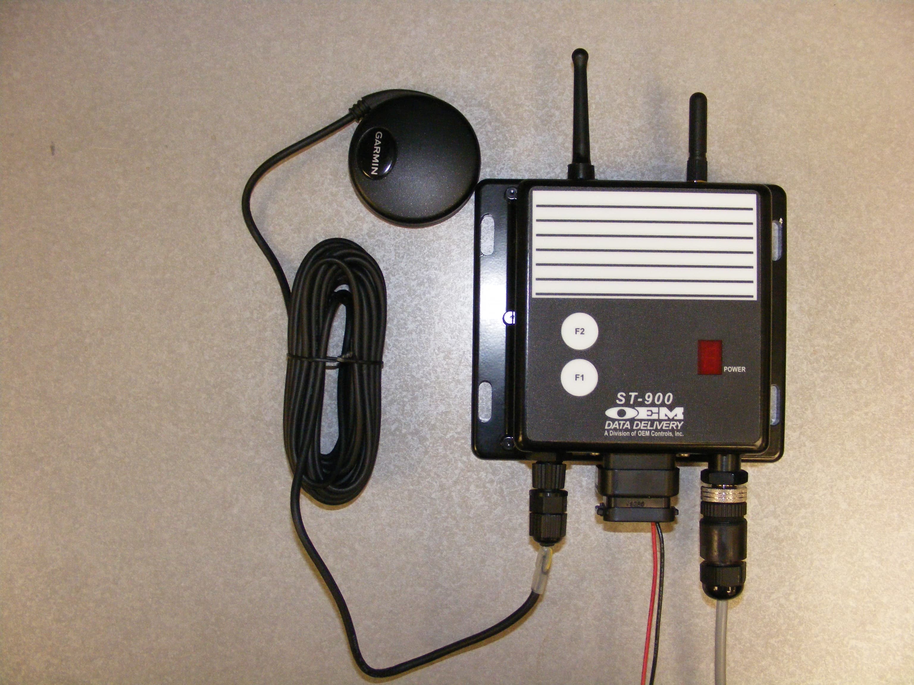
Click to zoom
Application Details
- Equipment Class
- DTS - Digital Transmission System
- Date of Grant
- Aug 04, 2010
- Application Purpose
- Original Equipment
- Date of Application
- Aug 04, 2010
- Equipment Note
- ST-5
- Frequency Range
- 2405.00000000 - 2475.00000000
- Company
- OEM Controls, Inc.
- Country
- United States
Documents & Files
Document Text
Text extracted from the exhibit documents filed with the FCC. Open a document above to read the original.
Users Manual
ST-900 Installation Guide and User’s Manual CELLULAR U Installation Guide and A Division of OEM Controls, Inc. 900 Installation Guide and User’s Manual ST-900 ELLULAR SERVICE TRACKER USER MANUAL Installation Guide and User’s Manual OEM Data Delivery, A Division of OEM Controls, Inc. 10 Controls Drive Shelton, CT 06484 203-929-8431 www.service-tracker.com DOC # 20977 Page 1 RACKER DOC # 20977 ST-900 Installation Guide and User’s Manual Page 2 COPYRIGHT: COPYRIGHT © 2009 BY OEM DATA DELIVERY, A DIVISION OF OEM CONTROLS, INC., ALL RIGHTS RESERVED. DISCLAIMER AND LIMITATION OF LIABILITY: OEM DATA DELIVERY UNDERTAKES NO RESPONSIBILITY FOR ANY LOSS OR CLAIMS BY THIRD PARTIES WHICH MAY ARISE THROUGH THE USE OF THIS HARDWARE. OEM DATA DELIVERY UNDERTAKES NO RESPONSIBILITY FOR ANY DAMAGE OR LOSS CAUSED BY DELETION OF DATA AS A RESULT OF MALFUNCTION, DEAD BATTERY, OR REPAIRS. BE SURE TO MAKE BACKUP COPIES OF ALL IMPORTANT DATA ON OTHER MEDIA TO PROTECT AGAINST DATA LOSS. WARNING: IT IS THE PURCHASER’S RESPONSIBILITY TO DETERMINE THE SUITABILITY OF OEM DATA DELIVERY PRODUCT FOR AN INTENDED APPLICATION AND TO ENSURE THAT IT IS INSTALLED AND GUARDED IN ACCORDANCE WITH ALL FEDERAL, STATE, LOCAL AND PRIVATE SAFETY AND HEALTH REGULATIONS, CODES AND STANDARDS. WARNING: NO MODIFICATIONS TO THE UNIT ARE TO BE MADE. ANY CHANGES OR MODIFICATIONS NOT EXPRESSLY APPROVED BY THE OEM CONTROLS, INC. COULD VOID THE PURCHASER’S AUTHORITY TO OPERATE THE EQUIPMENT. THIS DEVICE COMPLIES WITH PART 15 OF THE FCC RULES. OPERATION IS SUBJECT TO THE FOLLOWING TWO CONDITIONS: (1) THIS DEVICE MAY NOT CAUSE HARMFUL INTERFERENCE, AND (2) THIS DEVICE MUST ACCEPT ANY INTERFERENCE RECEIVED, INCLUDING INTERFERENCE THAT MAY CAUSE UNDESIRED OPERATION. DOCUMENT NUMBER: 20977 DATE OF REVISION: 6/14/10 – Rev. C ABOUT THIS GUIDE: THIS GUIDE PROVIDES BASIC INSTRUCTION ON THE USE OF THE ST-900 CELLULAR SERVICE TRACKER. DOC # 20977 ST-900 Installation Guide and User’s Manual Page 3 Introduction 4 General Information 4 Radio Communication 4 GPS Communication 4 GPRS Communication 4 Models Available 5 Schematic Model 100 6 Schematic Model 102 7 Schematic Model 103 8 Electrical Installation 9 Installing an ST-900 Cellular Service Tracker 13 Installing the GPS 15 Equipment Needed 15 ST-900 Features 16 Programming the ST-900 17 Setting an Equipment Profile 18 Loading your Profile 19 Diagnosing the ST-900 20 Technical Specifications 22 7 Segment Display 23 Contents DOC # 20977 ST-900 Installation Guide and User’s Manual Page 4 General Information OEM Data Delivery, a leading developer of rugged electronic tools for managing worksites and high-end equipment, has introduced a versatile system for tracking equipment at remote locations. The ST-900 generates the real-time information needed to maximize revenue and cut waste. The ST-900 is one of the most powerful, and versatile tools available for precise job costing. It was engineered for severe service performance at construction, landfill, rental and other complex operations. Implementation is quick and training typically requires just a few hours. The ST-900 works with the GoPod from OEM Data Delivery. This concealed computer installs in lube/fuel trucks, low boy trucks, and supervisor’s vehicles for additional process data capture, including fuel, driver logs, and mechanic work logs. It has a GPS antenna and a radio antenna. GPS coordinates are stamped into the record as hour data is collected. Information is collected passively, within range of a 300 foot line of sight, and transmitted via secure radio link. The ST-900 works remotely using cellular GPRS. This allows the user to capture data from the tracker, the profile, work/idle/run logs, latitude, longitude, travel logs, and count/duration logs. It also allows the user to disable or enable the ignition on the vehicle, profile the tracker, and modify the real time clock to adjust for daylight savings time and time zone differences. Radio Communication The radio will allow you to retrieve all ST-900 data, such as the profile, service alerts, work/idle/run/count duration logs, and GPS information (latitude and longitude). You can retrieve this data using a GoPod. The Aceeca/Gopod will allow the user to update (modify) the real time clock. The Aceeca will not be used to capture the work/idle/run, count/duration logs. GPS Communication The GPS will give the user the positional information of the ST-900 (Latitude and Longitude). The speed over ground is used to derive the cumulative machine mileage. GPRS Communication The GPRS will allow the user to have remote connectivity using cellular technology. The user can obtain information on a PC with OEM Server Software that will communicate with the ST- 900 using the GPRS network. The Cellular GPRS will allow you to retrieve all data, such as the count/duration logs. It also allows the user to disable/enable the ignition on the vehicle, profile the tracker and modify the real time clock to adjust for daylight saving time and time zone differences. DOC # 20977 ST-900 Installation Guide and User’s Manual Page 5 Product Cable Features ST-900-100 EPW/1174 Standard ST-900-101 EPW/1174 Standard and Computer Connection ST-900-102 EPWH/1191 Standard and Remote Starter Disable (RSD) ST-900-103 EPWH/1200 Standard and Data Logs The next few pages will display schematics of each of these models. ST-900 Models Available DOC # 20977 ST-900 Installation Guide and User’s Manual Page 6 DOC # 20977 ST-900 Installation Guide and User’s Manual Page 7 DOC # 20977 ST-900 Installation Guide and User’s Manual Page 8 DOC # 20977 ST-900 Installation Guide and User’s Manual Page 9 Electrical Installation DOC # 20977 ST-900 Installation Guide and User’s Manual Page 10 Electrical Installation DOC # 20977 ST-900 Installation Guide and User’s Manual Page 11 Electrical Installation DOC # 20977 ST-900 Installation Guide and User’s Manual Page 12 Electrical Installation DOC # 20977 ST-900 Installation Guide and User’s Manual Page 13 1. …
Text truncated - open the document above for the full version.
Cover Letter(s)
Northwest EMC TCB Compliance Opinion Rev. 12/08/09 SGST0011 Information about the Applicant Grantee (Company Name) OEM Controls, Inc. FCC Contact Person Paul Rohaly Address 10 Controls Drive City, State, Zip Shelton, CT 06484 Job Number SGST0011 Model ST-5 FCC ID YD7-ST-5XX Agent Approval Type Original Equipment Class DTS Digital Transmission System Rule Part 15.247 Overview This application is for an original certification of a Zigbee radio module FCC ID YD7-ST-5XX. Limited modular approval is sought for the model ST-5 radio, which is installed in the ST-900 service tracker. The ST-900 is mounted on a vehicle to monitor vehicle information such as fuel, CMH, Location, etc. The ST-5 radio transmits this information. Although the ST-900 contains a cellular modem (FCC ID: AU792U03G23710), software does not permit simultaneous transmission of the two radios. The device is considered a mobile radio and will not be used closer than 20 cm from all persons, but because of the low output power the device meets portable RF exposure conditions. Confidentiality requested for allowed files. Request is properly addressed and referenced. A letter listing the applicable modular requirements was submitted. Recommendation All items have been resolved and completed to my satisfaction; therefore I recommend this application for approval. Signature 7/14/2010 Dave Tolman, TCB Committee
External Photos
F igure 1: Zigbee antenna circled
ID Label/Location Info
1 1 2 2 AA BB PERMISSION TO USE OR DISCLOSE ANY INFORMATION HEREIN REV.DWG. NO. APPROVEDDATEDESCRIPTION REVISIONS SHT. REV MUST BE OBTAINED FROM OEM. THIS DRAWING IS THE SOLE PROPERTY OF OEM CONTROLS INC., 10 CONTROLS DRIVE, SHELTON, CT 06484, USA. THIS DOCUMENT CONTAINS OEM PROPRIETARY INFORMATION. WRITTEN PART NO. SCALE DWG NO. SHEET REV. SIZE PROJECTION: DESN APVD SALES DRAWN CHECKED APVD APVD ENG. BY DATE 10 Controls Drive − Shelton, CT 06484 Phone: (203) 929−8431 Fax.: (203) 929−7546 C CC Co oo on nn nt tt tr rr ro oo ol ll ls ss s, ,, , I II In nn nc cc c. .. . FINISH: MATERIAL: UNLESS OTHERWISE SPECIFIED .X ` `` `.1 TOLERANCE ` `` `.01 ‘.005 ‘.0010 .X .XXX .XX EDGES & BURRS. UNDIMENSIONED RADII: BREAK ALL SHARP CORNERS, DIMENSIONAL UNITS: .XXXX ` `` `1~ ~~ ~ ` `` `.5~ ~~ ~ ANGLES X A22105 1 A FCC LABEL FOR ST-5 EPLB/1195 A22105 A NTS 1 A ASHARP 6/2/10 INCHES 0 A ORIGINAL AJS 6/2/10 0.44 0.25 .05 PT HIGH TEXT 0.04 0.13 0.21 0.19 NOTES: 1) MAKE FROM OEM P/N: EPLB/693 1:1 SCALE 3:1 SCALE PRELIMINARY 1 1 2 2 AA BB PERMISSION TO USE OR DISCLOSE ANY INFORMATION HEREIN REV.DWG. NO. APPROVEDDATEDESCRIPTION REVISIONS SHT. REV MUST BE OBTAINED FROM OEM. THIS DRAWING IS THE SOLE PROPERTY OF OEM CONTROLS INC., 10 CONTROLS DRIVE, SHELTON, CT 06484, USA. THIS DOCUMENT CONTAINS OEM PROPRIETARY INFORMATION. WRITTEN PART NO. SCALE DWG NO. SHEET REV. SIZE PROJECTION: DESN APVD SALES DRAWN CHECKED APVD APVD ENG. BY DATE 10 Controls Drive − Shelton, CT 06484 Phone: (203) 929−8431 Fax.: (203) 929−7546 C CC Co oo on nn nt tt tr rr ro oo ol ll ls ss s, ,, , I II In nn nc cc c. .. . FINISH: MATERIAL: UNLESS OTHERWISE SPECIFIED .X ` `` `.1 TOLERANCE ` `` `.01 ‘.005 ‘.0010 .X .XXX .XX EDGES & BURRS. UNDIMENSIONED RADII: BREAK ALL SHARP CORNERS, DIMENSIONAL UNITS: .XXXX ` `` `1~ ~~ ~ ` `` `.5~ ~~ ~ ANGLES X A21915 1 A FCC LABEL FOR ST-900 EPLB/1189 A21915 A NTS 1 A ASHARP 4/5/10 INCHES 0 A ORIGINAL AJS 4/5/10 .38 .19 .10 PT HIGH TEXT 1.00 NOTES: 1) MAKE FROM OEM P/N: LL/317 .06 .38 .50 1:1 SCALE PRELIMINARY 3:1 SCALE DETAIL A SCALE 1 : 1 A AAA B BBB 1 111 2 222 A AAA B BBB F-11701 Rev. A 11-30-00 [A-TBlock-H] REV DESCRIPTION DATE REV. REVISIONS DWG. NO. SHT. APPROVED OEM PROPRIETARY INFORMATION. WRITTEN PERMISSION TO USE OR DISCLOSE ANY INFORMATION HEREIN MUST BE OBTA INED FROM OEM. THIS DRAWING IS THE SOLE PROPERTY OF OEM CONTROLS I NC., 10 CONTROLS DRIVE, SHELTON, CT 06484, USA. THI S DOCUMENT CONTAINS DATE PROJECTION: APVD SALES DESNENG.APVDAPVD CHECKED BYBYDRAWN 10 Controls Drive − Shelton, CT 06484 Phone: (203) 929−8431 Fax.: (203) 929−7546 PART NO. SCALE 1 1 DWG NO . SHEET C CCCo ooon nnnt tttr rrro oool llls sss, ,,, I IIIn nnnc ccc. ... REVSIZE BREAK ALL SHARP CORNERS, EDGES & BURRS. UNLESS OTHERWISE SPECIFIED UNDIMENSIONED RADII: ` .0010 ` .005 .XX ` .01 DIMENSIONAL UNITS: .XXXX .XXX TOLERANCE .X ` .1 .X ` .5 ~ ANGLES X ` 1 ~ A21914 1 A ASHARP 4/5/10 INCHES 0 ST−900 WITH FCC DECAL LOCATION A21914 A NTS 1 A MATERIAL: FINISH: A ORIGINAL AJS 4/5/10 A 1.5 PLACE DECALIN THIS LOCATION PRELIMINARY
Internal Photos
ST-5 Radio Module OEM Controls, Inc PCB Location ST-5 Zigbee Radio Module Top PCB Location ST-5 Radio Module OEM Controls, Inc PCB Location ST-5 Zigbee Radio Module Bottom PCB Location
Operational Description
ST-5 Radio Module OEM Controls Inc. Antenna Info The ST-5 Zigbee (802.15.4) Antenna device complies with the antenna requirements of paragraph 15.203. The production process guarantees that the antenna is permanently attached to the enclosure. Zigbee (802.15.4) Radio Antenna Information: Manufacturer: Centurion Model: WCP2400-MMCX4 Gain: 2.5 dBi Description: ½ wave dipole
RF Exposure Info
Compliance with 47 CFR 15.247(i) “Systems operating under the provisions of this section shall be operated in a manner that ensures that the public is not exposed to radio frequency energy levels in excess of the Commission's guidelines. See § 1.1307(b)(1) of this chapter.” The EUT is a Zigbee radio module used in a vehicle mounted device. It can be considered a mobile transmitter per 47 CFR 2.1091 because it is intended to be used greater than 20 cm from the head or torso of the user. The antenna is permanently attached to the enclosure. The antenna is a ½ wave dipole antenna with 2.5 dBi gain. The maximum peak conducted output power is 1.69 mW. The maximum peak power is 3.0 mW (EIRP) for FCC ID: YD7-ST-5XX. The transmit frequency is 2405 to 2475 MHz, therefore the EUT does not require routine SAR evaluation or MPE Estimates because it falls below the low power threshold of 60/f(GHz)mW. Please see this excerpt from KDB 447498D01 Mobile Portable RF Exposure v04, item 2)(a)(i): "a device may be used in portable exposure conditions with no restrictions on host platforms when either the source-based time-averaged output power is <=60/f(GHz)mW or all measured 1-g SAR are <0.4 W.kg." The applicant’s wireless radio, YD7-ST-5XX, is compliant with the requirements of FCC 15.247(i).
Test Report
OEM Controls, Inc ST-900 Report No. SGST0011 Report Prepared By www.nwemc.com 1-888-EMI-CERT © 2010 Northwest EMC, Inc 22975 NW Evergreen Parkway Suite 400 Hillsboro, Oregon 97124 Certificate of Test Last Date of Test: March 31, 2010 OEM Controls, Inc Model: ST-900 Emissions Test Description Specification Test Method Pass/Fail Spurious Radiated Emissions FCC 15.247:2010 ANSI C63.10:2009 Pass Occupied Bandwidth FCC 15.247:2010 ANSI C63.10:2009 Pass Output Power FCC 15.247:2010 ANSI C63.10:2009 Pass Band Edge Compliance FCC 15.247:2010 ANSI C63.10:2009 Pass Spurious Conducted Emissions FCC 15.247:2010 ANSI C63.10:2009 Pass Power Spectral Density FCC 15.247:2010 ANSI C63.10:2009 Pass Modifications made to the product See the Modifications section of this report Test Facility The measurement facility used to collect the data is located at: Northwest EMC, Inc. 22975 NW Evergreen Parkway, Suite 400 Hillsboro, OR 97124 Phone: (503) 844-4066 Fax: 844-3826 This site has been fully described in a report filed with and accepted by the FCC (Federal Communications Commission) and Industry Canada (Site filing #2834D-1). Approved By: Don Facteau, IS Manager NVLAP Lab Code: 200630-0 This report must not be used to claim product certification, approval, or endorsement by NVLAP, NIST, or any agency of the federal government of the United States of America. Product compliance is the responsibility of the client, therefore the tests and equipment modes of operation represented in this report were agreed upon by the client, prior to testing. This Report may only be duplicated in its entirety. The results of this test pertain only to the sample(s) tested. The specific description is noted in each of the individual sections of the test report supporting this certificate of test. Northwest EMC Revision History Revision 06/29/09 Revision Number Description Date Page Number 00 None Barometric Pressure The recorded barometric pressure has been normalized to sea level. Accreditations and Authorizations FCC Accredited by NVLAP for performance of FCC radio, digital, and ISM device testing. Our Open Area Test Sites, certification chambers, and conducted measurement facilities have been fully described in reports filed with the FCC and accepted by the FCC in letters maintained in our files. Northwest EMC has been accredited by ANSI to ISO / IEC Guide 65 as a product certifier. We have been designated by the FCC as a Telecommunications Certification Body (TCB). This allows Northwest EMC to certify transmitters to FCC specifications in accordance with 47 CFR 2.960 and 2.962. NVLAP Northwest EMC, Inc. is accredited under the United States Department of Commerce, National Institute of Standards and Technology, and National Voluntary Laboratory Accreditation Program for satisfactory compliance with the requirements of ISO/IEC 17025 for Testing Laboratories. The NVLAP accreditation encompasses Electromagnetic Compatibility Testing in accordance with the European Union EMC Directive 2004/108/EC, and ANSI C63.4. Additionally, Northwest EMC is accredited by NVLAP to perform radio testing in accordance with the European Union R&TTE Directive 1999/5/EEC, the requirements of FCC, and the RSS radio standards for Industry Canada. NVLAP LAB CODE 200629-0 NVLAP LAB CODE 200630-0 NVLAP LAB CODE 200676-0 NVLAP LAB CODE 200761-0 NVLAP LAB CODE 200881-0 Industry Canada Accredited by NVLAP for performance of Industry Canada RSS and ICES testing. Our Open Area Test Sites and certification chambers comply with RSS-Gen, Issue 2 and have been filed with Industry Canada and accepted. Northwest EMC has been accredited by ANSI to ISO / IEC Guide 65 as a product certifier. We have been designated by NIST and recognized by Industry Canada as a Certification Body (CB) per the APEC Mutual Recognition Arrangement (MRA). This allows Northwest EMC to certify transmitters to Industry Canada technical requirements. (Site Filing Numbers - Hillsboro: 2834D-1, 2834D-2, Sultan: 2834C-1, Irvine: 2834B-1, 2834B-2, Brooklyn Park: 2834E-1) CAB Designated by NIST and validated by the European Commission as a Conformity Assessment Body (CAB) to conduct tests and approve products to the EMC directive and transmitters to the R&TTE directive, as described in the U.S. - EU Mutual Recognition Agreement. NEMKO Assessed and accredited by NEMKO (Norwegian testing and certification body) for European emissions and immunity testing. As a result of NEMKO's laboratory assessment, they will accept test results from Northwest EMC, Inc. for product certification (Authorization No. ELA 119). Accreditations and Authorizations Australia/New Zealand The National Association of Testing Authorities (NATA), Australia has been appointed by the ACA as an accreditation body to accredit test laboratories and competent bodies for EMC standards. Accredited test reports or assessments by competent bodies must carry the NATA logo. Test reports made by an overseas laboratory that has been accredited for the relevant standards by an overseas accreditation body that has a Mutual Recognition Agreement (MRA) with NATA are also accepted as technical grounds for product conformity. The report should be endorsed with the respective logo of the accreditation body (NVLAP). VCCI Accepted as an Associate Member to the VCCI, Acceptance No. 564. Conducted and radiated measurement facilities have been registered in accordance with Regulations for Voluntary Control Measures, Article 8. (Registration Numbers. - Hillsboro: C-1071, R-1025, G-84, C-2687, T-1658, and R-2318, Irvine: R-1943, G-85, C- 2766, and T-1659, Sultan: R-871, G-83, C-1784, and T-1511, Brooklyn Park: R-3125, G-86, G-141, C-3464, and T-1634). BSMI Northwest EMC has been designated by NIST and validated by C-Taipei (BSMI) as a CAB to conduct tests as described in the APEC Mutual Recognition Agreement (US0017). License No.SL2-IN-E-1017. GOST Northwest EMC, Inc. has been assessed and accredited by the Russian Certification bodies Certinform VNIINM…
Text truncated - open the document above for the full version.
Test Setup Photos
NORTHWEST EMC OCCUPIED BANDWIDTH XMit 2010.01.14 NORTHWEST EMC OUTPUT POWER XMit 2010.01.14 NORTHWEST EMC BAND EDGE COMPLIANCE XMit 2010.01.14 NORTHWEST EMC SPURIOUS CONDUCTED EMISSIONS XMit 2010.01.14 NORTHWEST EMC POWER SPECTRAL DENSITY XMit 2010.01.14 NORTHWEST EMC SPURIOUS RADIATED EMISSIONS PSA 2008.07.21 NORTHWEST EMC SPURIOUS RADIATED EMISSIONS PSA 2008.07.21 NORTHWEST EMC SPURIOUS RADIATED EMISSIONS PSA 2008.07.21
Contact Information
Applicant
Paul M Rohaly(Director of Engineering)
Test Firm
Northwest EMC, Inc.Greg Kiemel
Technical Specifications
| # | Rule Parts | Frequency Range | Power Output |
|---|---|---|---|
| 1 | 15C | 2.40 GHz - 2.48 GHz | 1.69 mW |
Other Applications from OEM Controls, Inc.
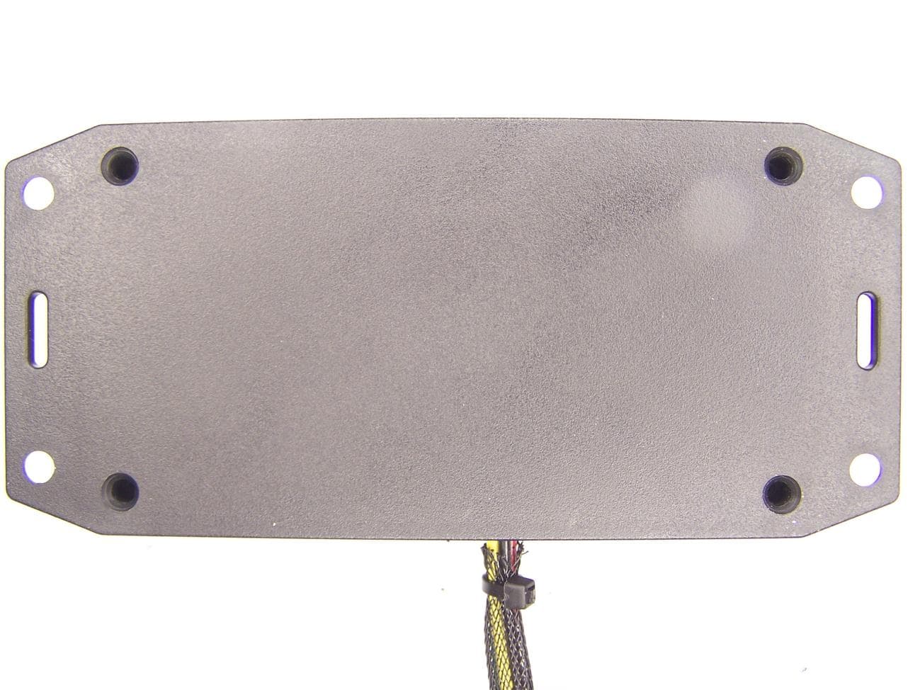
YD7-ST550
Apr 28, 2011ST-550 Radio Product
Equipment Class
DTS - Digital Transmission System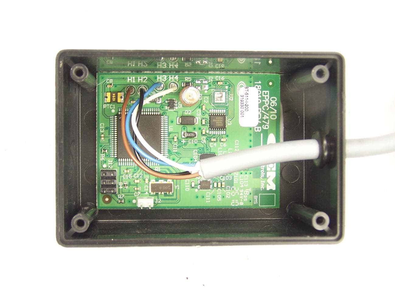
YD7-ST511
Apr 28, 2011ST-511 Radio Primary
Equipment Class
DTS - Digital Transmission System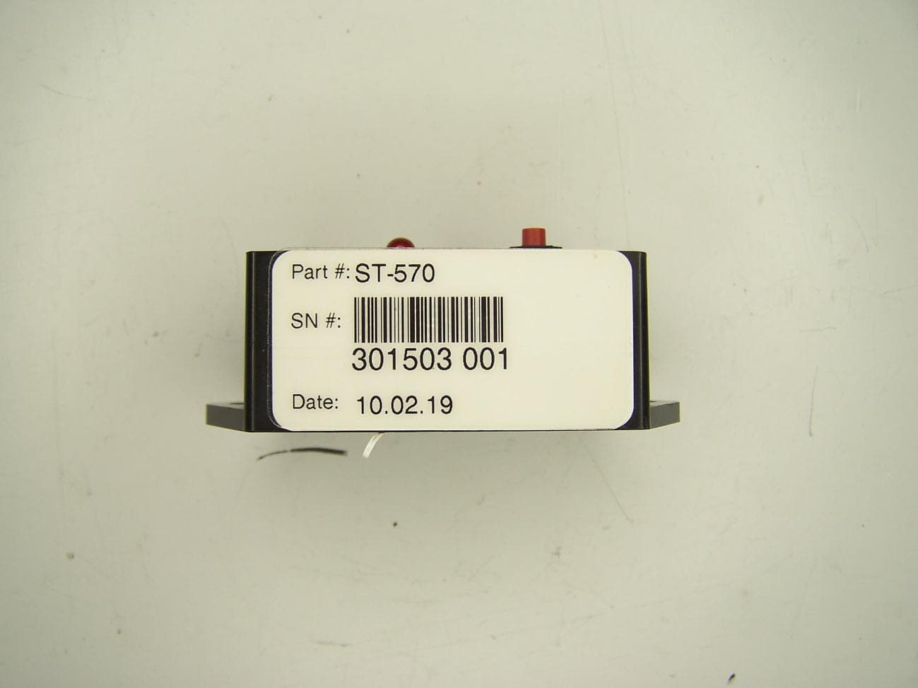
YD7-ST570RFID
Apr 28, 2011ST-570 RFID Cube
Equipment Class
DTS - Digital Transmission System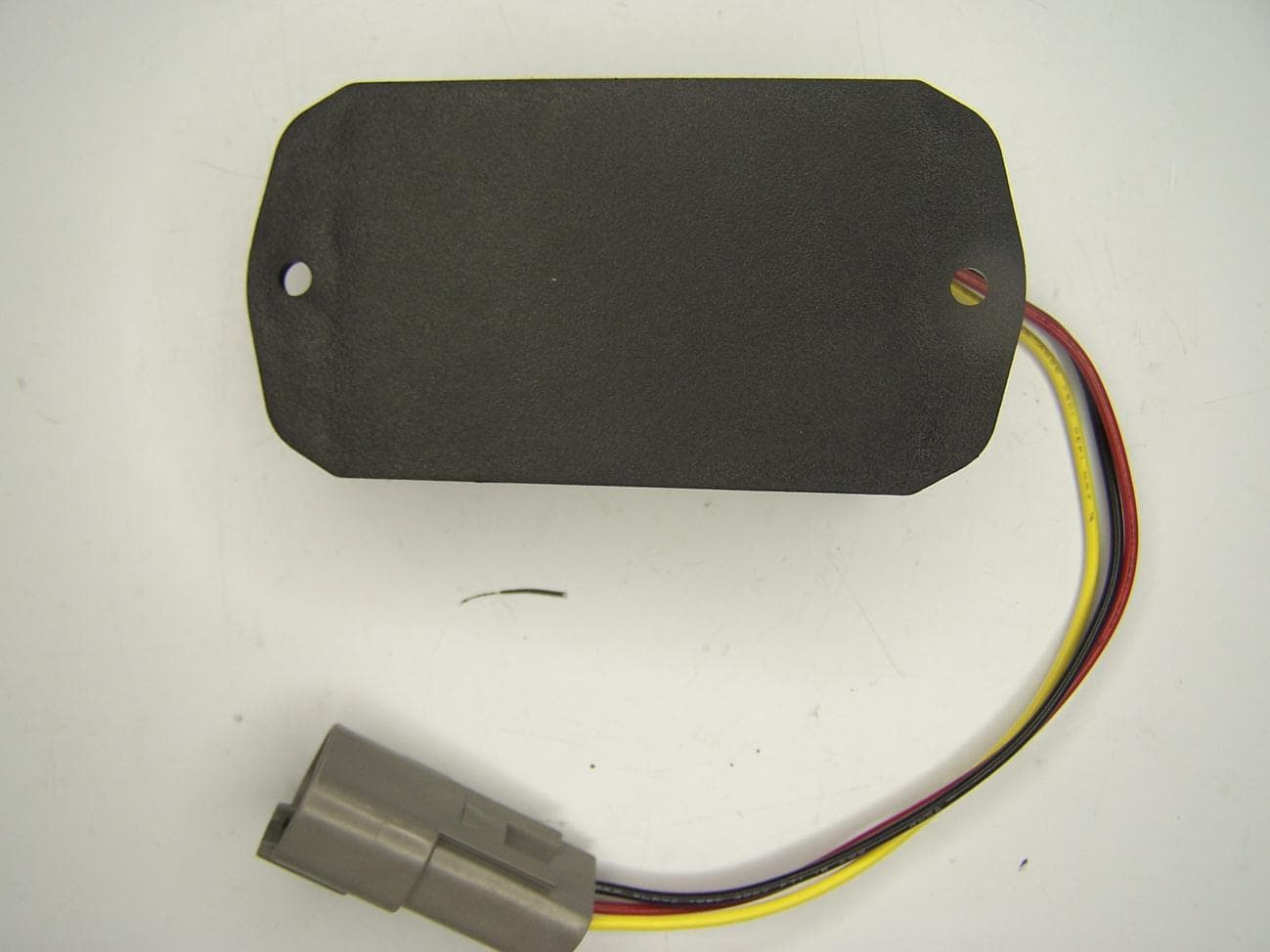
YD7-ST570HVS
Apr 28, 2011ST-570 RFID Hour Meter
Equipment Class
DTS - Digital Transmission System