YE5-DPWC610CAC/PIV Smart Card Reader (Slimline Bay)
HON HAI PRECISION IND. Co., LTD.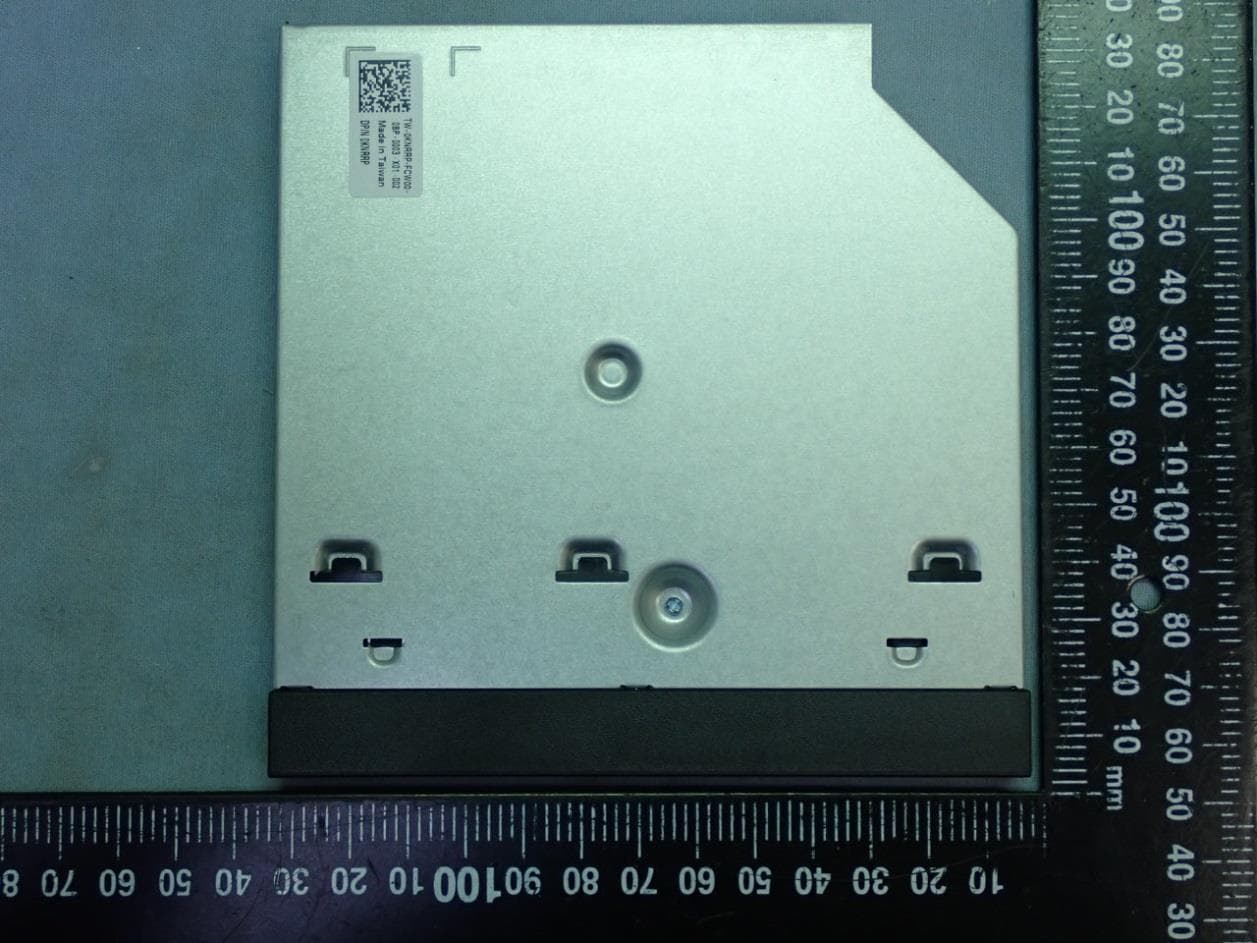
Click to zoom
Application Details
- Equipment Class
- DXX - Part 15 Low Power Communication Device Transmitter
- Date of Grant
- Jan 10, 2021
- Application Purpose
- Original Equipment
- Date of Application
- Jan 10, 2021
- Equipment Note
- CAC/PIV Smart Card Reader (Slimline Bay)
- Frequency Range
- 13.56000000 - 13.56000000
- Country
- Taiwan
Documents & Files
Document Text
Text extracted from the exhibit documents filed with the FCC. Open a document above to read the original.
Users Manual
CAC/PIV Module 3 Manual Key Characteristic USB signal input Support contactless card utilizes NFC technology Support contact card utilizes card reader Introduction This module provides a method to enable security access to the system or applications via an access card/badge. This module design is taken the chip BCM BC58202 as main controlled chip. And can support contactless card by NFC technology and contact card by card reader. Module fits in slim line ODD form factor. Module include the USH PCBA, contact reader and NFC antenna. Dimension (millimeter) Specification Hardware The input signal is standard USB signal from host system to the main chip BC58202, And the contactless and contact card reader function is achieved through that main chip. Contact for signal input Header1X5 Signal VCC, +5V, GND, USB- #1, USB+#1 FCC: This equipment has been tested and found to comply with the limits for a Class B digital device, pursuant to Part 15 of the FCC Rules. These limits are designed to provide reasonable protection against harmful interference in a residential installation. This equipment generates, uses and can radiate radio frequency energy and, if not installed and used in accordance with the instructions, may cause harmful interference to radio communications. However, there is no guarantee that interference will not occur in a particular installation. If this equipment does cause harmful interference to radio or television reception, which can be determined by turning the equipment off and on, the user is encouraged to try to correct the interference by one of the following measures: Reorient or relocate the receiving antenna. Increase the separation between the equipment and receiver. Connect the equipment into an outlet on a circuit different from that to which the receiver is connected. Consult the dealer or an experienced radio/TV technician for help. This device complies with Part 15 of the FCC Rules. Operation is subject to the following two conditions: (1) This device may not cause harmful interference, and (2) this device must accept any interference Exposure to Radio Frequency Radiation: This equipment complies with FCC radiation exposure limits set forth for an uncontrolled environment. This equipment should be installed and operated with minimum distance 20cm between the radiator & your body. IC: This device complies with Industry Canada license-exempt RSS standard(s). Operation is subject to the following two conditions: (1) this device may not cause interference, and (2) this device must accept any interference, including interference that may cause undesired operation of the device. Exposure to Radio Frequency Radiation:: This equipment complies with IC radiation exposure limits set forth for an uncontrolled environment. This equipment should be installed and operated with minimum distance 20cm between the radiator & your body. French: Cet appareil est conforme aux normes RSS exempts de licence d'Industrie Canada. Son fonctionnement est soumis aux deux conditions suivantes: (1) cet appareil ne doit pas causer d’interférences et (2) cet appareil doit accepter toute interférence, y compris les interférences pouvant provoquer un fonctionnement indésirable de l’appareil. Exposure to Radio Frequency Radiation: Cet équipement est conforme aux limites d'exposition aux rayonnements IC définies pour un environnement non contrôlé. Cet équipement doit être installé et utilisé à une distance minimale de 20 cm entre le radiateur et votre corps.
Cover Letter(s)
102920 – 13 Authority to Act as Agent Date: January 4, 2021 American Certification Body, Inc. 6731 Whittier Avenue Suite C110 McLean, VA 22101 To Whom It May Concern: ______ AUDIX Technology Corporation ______ is authorized to act on our behalf, until otherwise notified, for applications to American Certification Body, Inc. (ACB). We certify that we are not subject to denial of federal benefits, that includes FCC benefits, pursuant to Section 5301 of the Anti-Drug Abuse Act of 1988, 21 U.S.C. 862. Further, no party, as defined in 47 CFR 1.2002 (b), to the application is subject to denial of federal benefits, that includes FCC benefits. We also declare that the information provided to the FCC is true and correct to the best of our knowledge (47 CFR 2.911(d)) and we have been informed of the grantee responsibilities (47 CFR 2.909) with regard to certified equipment. Thank you, Agency Agreement Expiration Date: _____January 04, 2022_____ By: __________________________ _Olivia Lin___________________ (Signature 1 ) (Print name) Title: ___RCE-Agency-Regulatory______ On behalf of: _____HON HAI PRECISION IND. Co., LTD.______ (Company Name) Telephone: _____+886-2-7705-7999 Ext:51012234_______ 1 - Must be signed by applicant contact given for applicant on the FCC site, or by the authorized agent if an appropriate authorized agent letter has been provided. Letters should be placed on appropriate letterhead.
Cover Letter(s)
102920 – 13 Request for Confidentiality Date: January 4, 2021 Subject: Confidentiality Request for: ______ FCC ID: YE5-DPWC610 / IC: 4613B-DPWC610 ______ Pursuant to FCC 47 CFR 0.457(d) and 0.459 and IC RSP-100, Section 12.4, the applicant requests that a part of the subject FCC application be held confidential. Type of Confidentiality Requested Exhibit ☐ Short Term Permanent Block Diagrams ☐ Short Term External Photos ☐ Short Term ☐Permanent * 2 Internal Photos ☐ Short Term Permanent Operation Description/Theory of Operation ☐ Short Term ☐ Permanent Parts List & Placement/BOM ☐ Short Term ☐ Permanent Tune-Up Procedure ☐ Short Term Permanent Schematics ☐ Short Term Test Setup Photos ☐ Short Term ☐Permanent * 3 User’s Manual ______ HON HAI PRECISION IND. Co., LTD.______ has spent substantial effort in developing this product and it is one of the first of its kind in industry. Having the subject information easily available to "competition" would negate the advantage they have achieved by developing this product. Not protecting the details of the design will result in financial hardship. Permanent Confidentiality: The applicant requests the exhibits listed above as permanently confidential be permanently withheld from public review due to materials that contain trade secrets and proprietary information not customarily released to the public. Short-Term Confidentiality: The applicant requests the exhibits selected above as short term confidential be withheld from public view for a period of ___ ___ days from the date of the Grant of Equipment Authorization and prior to marketing. This is to avoid premature release of sensitive information prior to marketing or release of the product to the public. Applicant is also aware that they are responsible to notify ACB in the event information regarding the product or the product is made available to the public before the requested period has expired. ACB will then release the documents listed above for public disclosure pursuant to FCC Public Notice DA 04-1705. NOTE for Industry Canada Applications: IC currently only distinguishes Permanent Confidentiality exhibits as shown above. Short Term confidentiality is not considered applicable to IC applications. Sincerely, By: __________________________ _______ Olivia Lin_________________ (Signature/ RCE-Agency-Regulatory 3 ) (Print name) 2 - The asterisked items (*) require further information to be provided to ACB before permanent confidentiality will beextended to these exhibits. Please refer to FCC KDB 726920 and the specific Document link for D01 found at: https://apps.fcc.gov/oetcf/kdb/forms/FTSSearchResultPage.cfm?switch=P&id=41731 and review section II, 3) regarding specific information that must accompany these requests. 3 - Must be signed by applicant contact given for applicant on the FCC site, or by the authorized agent if an appropriate authorized agent letter has been provided. Letters should be placed on appropriate letterhead.
External Photos
HON HAI PRECISION IND. Co., LTD. CAC/PIV Smart Card Reader (Slimline Bay) Model : DPWC610 EUT External Photos Figure 1 General Appearance (Front View) Figure 2 General Appearance (Back View) HON HAI PRECISION IND. Co., LTD. CAC/PIV Smart Card Reader (Slimline Bay) Model : DPWC610 Figure 3 General Appearance (Side View) Figure 4 General Appearance (Side View) HON HAI PRECISION IND. Co., LTD. CAC/PIV Smart Card Reader (Slimline Bay) Model : DPWC610 Figure 5 General Appearance (Top View) Figure 6 General Appearance (Bottom View)
ID Label/Location Info
HON HAI PRECISION IND. Co., LTD. CAC/PIV Smart Card Reader (Slimline Bay) Model : DPWC610 FCC ID/IC Label Location Label Placement Location FCC ID/IC Label Format
Internal Photos
HON HAI PRECISION IND. Co., LTD. CAC/PIV Smart Card Reader (Slimline Bay) Model : DPWC610 EUT Internal Photos Figure 7 Internal View (Removed Cover) Figure 8 Internal View HON HAI PRECISION IND. Co., LTD. CAC/PIV Smart Card Reader (Slimline Bay) Model : DPWC610 Figure 9 Internal View (Main Board, Front View) Figure 10 Internal View (Main Board, Back View) NFC Chip HON HAI PRECISION IND. Co., LTD. CAC/PIV Smart Card Reader (Slimline Bay) Model : DPWC610 Figure 11 Internal View (NFC Chip View) Figure 12 Internal View HON HAI PRECISION IND. Co., LTD. CAC/PIV Smart Card Reader (Slimline Bay) Model : DPWC610 Figure 13 Internal View Figure 14 Internal View NFC Antenna HON HAI PRECISION IND. Co., LTD. CAC/PIV Smart Card Reader (Slimline Bay) Model : DPWC610 Figure 15 Internal View (NFC Antenna, Front View) Figure 16 Internal View (NFC Antenna, Back View) HON HAI PRECISION IND. Co., LTD. CAC/PIV Smart Card Reader (Slimline Bay) Model : DPWC610 Figure 17 Internal View (Internal Board, Front View) Figure 18 Internal View (Internal Board, Back View)
Test Report
Page 1 of 23 Audix Technology Corp. Tel: +886 2 26099301 No. 53-11, Dingfu, Linkou, Dist., Fax: +886 2 26099303 New Taipei City244,Taiwan File Number: C1M2012046 Report Number: EM-F200615 This test report may be reproduced in full only. The document may only be updated by Audix Technology Corp. personnel. Any changes will be noted in the Document History section of the report. FCC 15.225 & RSS-210 13.56MHz Test Report for HON HAI PRECISION IND. Co., LTD. No. 2, Ziyou St., Tucheng Dist., New Taipei City 236, Taiwan Product Name : CAC/PIV Smart Card Reader (Slimline Bay) Model Name : DPWC610 Brand : DELL FCC ID : YE5-DPWC610 IC : 4613B- DPWC610 Prepared by: : AUDIX Technology Corporation, EMC Department The test report is based on a single evaluation of one sample of the above-mentioned products. It does not imply an assessment of the whole production and does not permit the use of the test lab logo. Page 2 of 23 Audix Technology Corp. Tel: +886 2 26099301 No. 53-11, Dingfu, Linkou, Dist., Fax: +886 2 26099303 New Taipei City244,Taiwan File Number: C1M2012046 Report Number: EM-F200615 This test report may be reproduced in full only. The document may only be updated by Audix Technology Corp. personnel. Any changes will be noted in the Document History section of the report. TABLE OF CONTENTS Description Page TEST REPORT ................................................................................................................................... 3 1. REVISION RECORD OF TEST REPORT ............................................................................ 5 2. SUMMARY OF TEST RESULTS ........................................................................................... 6 3. GENERAL INFORMATION ................................................................................................... 7 3.1. Description of Application .............................................................................................................. 7 3.2. Description of EUT ......................................................................................................................... 8 3.3. Antenna Information ....................................................................................................................... 8 3.4. EUT Specifications Assessed in Current Report ............................................................................. 8 3.5. Description of Key Components ..................................................................................................... 8 3.6. Test Configuration ........................................................................................................................... 9 3.7. Tested Supporting System List ........................................................................................................ 9 3.8. Setup Configuration ....................................................................................................................... 10 3.9. Operating Condition of EUT ......................................................................................................... 10 3.10. Description of Test Facility ........................................................................................................... 11 3.11. Measurement Uncertainty ............................................................................................................. 12 4. MEASUREMENT EQUIPMENTLIST ................................................................................. 13 4.1. Conducted Emission Measurement ............................................................................................... 13 4.2. Radiated Emission Measurement .................................................................................................. 13 4.3. RF Measurement ........................................................................................................................... 13 5. CONDUCTED EMISSION ..................................................................................................... 14 5.1. Block Diagram of Test Setup ........................................................................................................ 14 5.2. Conducted Emission Limit ............................................................................................................ 14 5.3. Test Procedure ............................................................................................................................... 14 5.4. Test Results ................................................................................................................................... 15 6. RADIATED EMISSION (IN-BAND) .................................................................................... 16 6.1. Block Diagram of Test Setup ........................................................................................................ 16 6.2. Radiated Emission Limits .............................................................................................................. 17 6.3. Test Procedure ............................................................................................................................... 17 6.4. Test Results ................................................................................................................................... 17 7. RADIATED EMISSION (OUT-BAND) ................................................................................ 18 7.1. Block Diagram of Test Setup ........................................................................................................ 18 7.2. Radiated Emission Limits .............................................................................................................. 19 7.4. Test Procedure ............................................................................................................................... 20 7.5. Measurement Result Explanation .............................................…
Text truncated - open the document above for the full version.
Test Setup Photos
APPENDIX B-Page 1 of 3 AUDIX Technology Corp. Tel: +886 2 26099301 No. 53-11, Dingfu, Linkou, Dist., Fax: +886 2 26099303 New Taipei City244, Taiwan File Number: C1M2012046 Report Number: EM-F200615 This test report may be reproduced in full only. The document may only be updated by Audix Technology Corp. personnel. Any changes will be noted in the Document History section of the report. B.1 Conducted Emission Measurement FRONT VIEW BACK VIEW APPENDIX B-Page 2 of 3 AUDIX Technology Corp. Tel: +886 2 26099301 No. 53-11, Dingfu, Linkou, Dist., Fax: +886 2 26099303 New Taipei City244, Taiwan File Number: C1M2012046 Report Number: EM-F200615 This test report may be reproduced in full only. The document may only be updated by Audix Technology Corp. personnel. Any changes will be noted in the Document History section of the report. B.2 Radiated Measurement at Chamber Frequency Range 9kHz to 30MHz Frequency Range 30MHz to 1GHz APPENDIX B-Page 3 of 3 AUDIX Technology Corp. Tel: +886 2 26099301 No. 53-11, Dingfu, Linkou, Dist., Fax: +886 2 26099303 New Taipei City244, Taiwan File Number: C1M2012046 Report Number: EM-F200615 This test report may be reproduced in full only. The document may only be updated by Audix Technology Corp. personnel. Any changes will be noted in the Document History section of the report. B.3 RF Measurement
Contact Information
Applicant
Jeffrey Wu(Manager)
Technical Contact
AUDIX Technology CorporationBen Cheng
+886226099301
NO. 53-11, Dingfu, Linkou Dist., · New Taipei City · Taiwan
Test Firm
Audix Technology CorporationAllen Wang
Technical Specifications
| # | Rule Parts | Frequency Range | Power Output |
|---|---|---|---|
| 1 | 15C | 13.56 MHz - 13.56 MHz | - |
Other Applications from HON HAI PRECISION IND. Co., LTD.
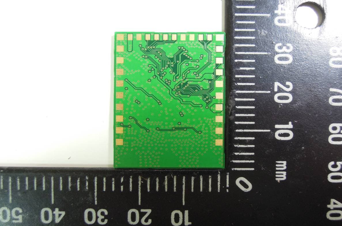
YE5-WBUB15
Nov 22, 2015801.11 a/b/g/n/ac WLAN and BT 4.1 Combo Module
Equipment Class
DTS - Digital Transmission System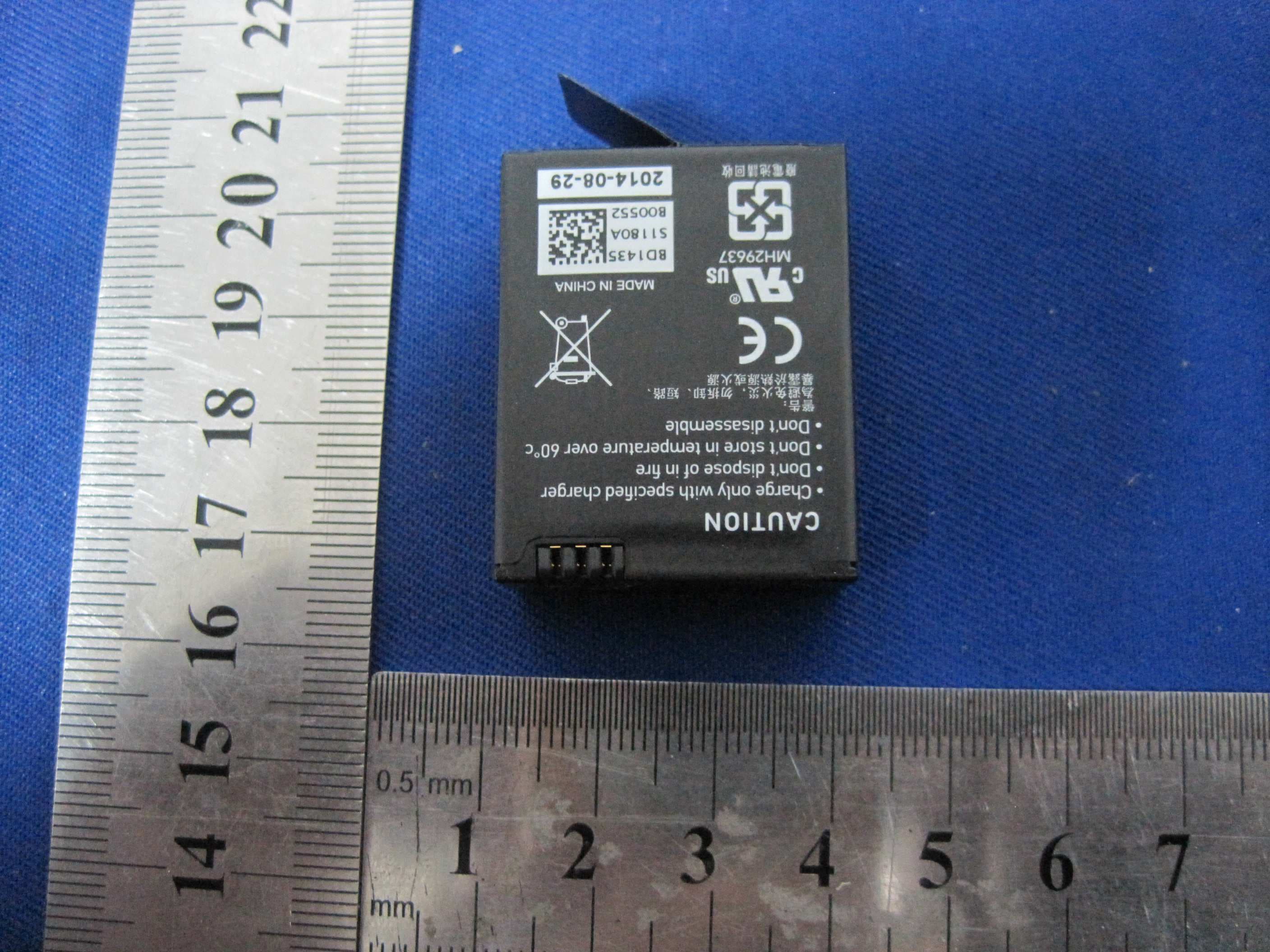
YE5-NABIF001
Sep 25, 2014Square HD
Equipment Class
DTS - Digital Transmission System
YE5-WRIG
May 19, 2010WRIG
Equipment Class
DSS - Part 15 Spread Spectrum Transmitter