YEETM21TELEMETRY TRANSCEIVER MODULE
Datapaq Limited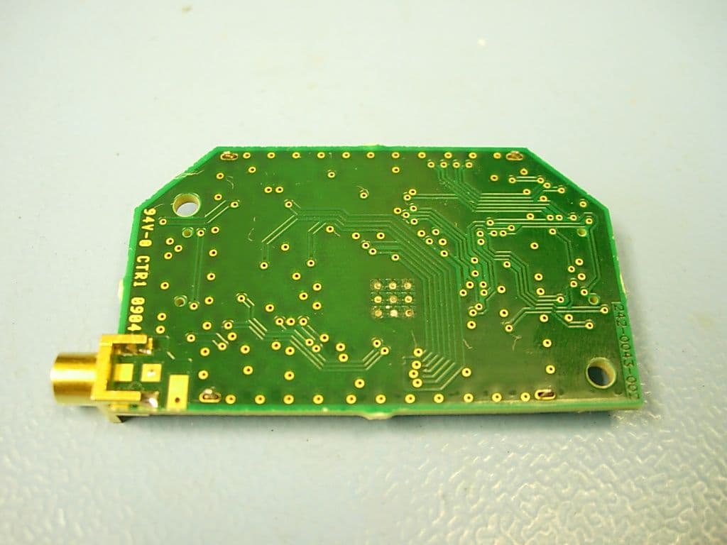
Click to zoom
Application Details
- Equipment Class
- TNB - Licensed Non-Broadcast Station Transmitter
- Date of Grant
- Jun 27, 2010
- Application Purpose
- Original Equipment
- Date of Application
- Jun 27, 2010
- Equipment Note
- TELEMETRY TRANSCEIVER MODULE
- Frequency Range
- 463.52500000 - 463.97500000
- Company
- Datapaq Limited
- Country
- United Kingdom
Documents & Files
Document Text
Text extracted from the exhibit documents filed with the FCC. Open a document above to read the original.
Users Manual
TM21 Radio- telemetry System USER MANUAL for Datapaq Tracker Systems with Issue 1 MA5940A TM21 Radio-telemetry System for Datapaq Tracker Systems with User Manual Issue 1 Europe & Asia Datapaq Ltd. 160 Cowley Road Cambridge CB4 0GU England Tel. +44-(0)1223-423141 Fax +44-(0)1223-423306 E-mail [email protected] www.datapaq.com North & South America Datapaq, Inc. 187 Ballardvale Street Wilmington, MA 01887 USA Tel. +1-978-988 9000 Fax +1-978-988 0666 E-mail [email protected] www.datapaq.com Datapaq is the world’s leading manufacturer of process temperature-monitoring instrumentation. The company maintains this leadership by continual development of its advanced, easy-to-use Tracker systems. DATAPAQ PART NO. MA5940A © Datapaq Ltd., Cambridge, UK 2010 All rights reserved Datapaq Ltd. makes no representations or warranties of any kind whatsoever with respect to the contents hereof and specifically disclaims any implied warranties of merchantability or fitness for any particular purpose. Datapaq Ltd. shall not be liable for errors contained herein or for incidental or consequential damages in connection with the furnishing, performance or use of the Datapaq software, associated hardware or this material. Datapaq Ltd. reserves the right to revise this publication from time to time and to make changes to the content hereof without obligation to notify any person of such revisions or changes. Microsoft and Windows are registered trademarks of Microsoft Corporation. Manual set in 10 pt Gill Sans. User manuals are available in other languages; contact Datapaq for details. SAFETY WARNINGS For safe use of Datapaq equipment, always: •Take care to follow its supplied instructions. •Observe any warning signs shown on the equipment itself. Indicates potential hazard. On Datapaq equipment this normally warns of high temperature, but where you see the symbol you should consult the manual for further explanation. Warns of high temperatures. Where this symbol appears on Datapaq equipment, the surface of the equipment may be excessively hot (or excessively cold) and may thus cause skin burns. The following product types TM21 Transmitter and Receiver manufactured by Datapaq Ltd., 160 Cowley Road, Cambridge CB4 0GU, UK comply with the requirements of regional directives as follows. European Community Council Directive 2004/108/EC – Electromagnetic compatibility (EMC) – electrical equipment for measurement, control and laboratory use EN 61326-1:2006 – Group 1, Class B equipment – Emissions section only EN 61326-1:2006 – Industrial Location Immunity – Immunity section only. (For cables up to 30 m in length, a surge test is required only on the mains power supply, not on the cable; Performance Criterion A is achieved. For cables longer than 30 m, the Long Signal 1-kV Line–Earth Surge test is applied, IEC 61000-4- 5; Performance Criterion C is achieved.) Council Directive 99/5/EC – Radio and telecommunication terminal equipment (RTTE) EN 300 220-1:2000 Council Directive 2006/95/EC – Low-voltage equipment EN 61010-1:2001 Council Directive 2002/95/EC – Restriction of the use of certain hazardous substances in electrical and electronic equipment (RoHS) Datapaq temperature-monitoring equipment is exempt from the directive under EEE Category 9 Monitoring and Control Instruments. This Datapaq product nevertheless uses RoHS- compliant components and manufacturing processes. Federal Communications Commission, USA Electromagnetic Compatibility Directive for digital devices CFR47:2007 Class A – Code of Federal Regulations: Part 15 Subpart B, Radio Frequency Devices, Unintentional radiators CFR 47 Part 90: Private Land Mobile Radio Services This equipment contains Transceiver Module FCC ID: YEETM21. This device complies with part 15 of the FCC Rules. Operation is subject to the following two conditions: (1) This device may not cause harmful interference, and (2) this device must accept any interference, including interference that may cause undesired operation. FCC 15.21 – Changes or modifications to this equipment, not expressly approved by Datapaq, could void the user’s authority to operate the equipment. FCC 15.105 – Note: This equipment has been tested and found to comply with the limits for a Class A digital device, pursuant to part 15 of the FCC Rules. These limits are designed to provide reasonable protection against harmful interference when the equipment is operated in a commercial environment. This equipment generates, uses, and can radiate radio frequency energy and, if not installed and used in accordance with the instruction manual, may cause harmful interference to radio communications. Operation of this equipment in a residential area is likely to cause harmful interference in which case the user will be required to correct the interference at his own expense. Industry Canada This Class A digital apparatus complies with Canadian ICES-003. RSS-119 Issue 9: Land Mobile and Fixed Radio Transmitters and Receivers Operating in the Frequency Range 27.41–960 MHz This equipment contains Module IC ID: 9012A- TM21. The abbreviation, IC, before the registration number signifies that registration was performed based on a Declaration of Conformity indicating that Industry Canada technical specifications were met. It does not imply that Industry Canada approved the equipment. CONTENTS 7 Introduction 9 Hardware Specifications 9 Transmitter 10 Primary Receiver 11 Secondary Receiver 13 Setting Up the System 13 Setting Up Receivers 17 Establishing Connection with Insight 17 Changing the System’s Frequency 18 Setting Up the Transmitter Antenna 19 Setup and Procedures in Specific Industries 19 Furnace Industry 20 Ceramics Industry 24 Oven Industry 25 Food Industry 27 Electronics Assembly Industry 27 Datapaq Service Department 29 Running a Temperature Profile 29 Resetting the Logger and Starting the Run 33 Real-time Data Collection 36 Recovering the Logger and Downloading Data 38 Using Multiple Loggers TM21 RADIO TELEMETRY Introd…
Text truncated - open the document above for the full version.
Block Diagram
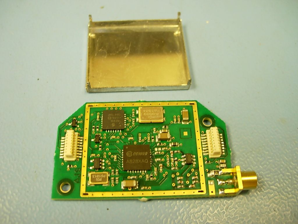
RF In/Out Digital Communications In/Out (I 2 C bus) PIC Microcontroller CC1020 RF Transceiver Power In 8MHz XTAL 14.7456MHz XTAL Power Supply Filtering & Decoupling Low Pass RF Filter TM21 RF Transceiver Module Block Diagram of TM21 Transceiver Module Thermal Sensor RF O/P Matching RF I/P Matching RF Switch
Cover Letter(s)
Deanland House 160 Cowley Road Cambridge CB4 0GU, UK. Federal Communications Commission Authorization and Evaluation Division Confidentiality Request regarding application for certification of FCC ID: YEETM21 Pursuant to Sections 0.457 and 0.459 of the Commission’s Rules, we hereby request confidential treatment of information accompanying this application as outlined below: Exhibit Type File Name Schematics TM21 Schem.pdf Parts List TM21 PartsLst.pdf The above materials contain trade secrets and proprietary information not customarily released to the public. The public disclosure of these materials may be harmful to the applicant and provide unjustified benefits to its competitors. The applicant understands that pursuant to Section 0.457 of the Rules, disclosure of this application and all accompanying documentation will not be made before the date of the Grant for this application. Sincerely, Ceri Grenyer Senior Electronics Engineer
Cover Letter(s)
Deanland House 160 Cowley Road Cambridge CB4 0GU, UK. Modular Approval Request Letter for Datapaq Transceiver Module, TM21A FCC ID: YEETM21 A Limited Modular Approval (LMA) is sought for the Datapaq TM21A Transceiver module under section CFR47 part 15.212(b). This is applied for with the understanding that Datapaq Ltd. will retain full control over the design and use of the module and ensure that it is only fitted into appropriate equipment according to the requirements. Limited Modular Approval is sought for the TM21 Transceiver module since it does not meet all the requirements for Modular Approval as indicated below: 1. The modular transmitter must have its own RF shielding. a. The TM21 Transceiver module complies with this requirement. 2. The modular transmitter must have buffered modulation/data inputs. a. The TM21 Transceiver module does not have buffered inputs; therefore Limited Modular Approval is requested. This module was designed solely for Datapaq Ltd and the design is under Datapaq Ltd control which ensures that this module will only be fitted to host devices that have the appropriate interface requirements. 3. The modular transmitter must have its own power supply regulation. a. The TM21 Transceiver module does not regulate the power rails; therefore Limited Modular Approval is requested. This module was designed solely for Datapaq Ltd and the design is under Datapaq Ltd control which ensures that this module will only be fitted to host devices that have the appropriate power supply requirements. 4. The modular transmitter must comply with the antenna requirements of Section 15.203 and 15.204(c). a. The TM21 Transceiver module complies with this requirement. 5. The modular transmitter must be tested in a stand-alone configuration. a. The TM21 Transceiver module was tested accordingly and complies with this requirement. 6. The modular transmitter must be labeled with its own FCC ID number, and, if the FCC ID is not visible when the module is installed inside another device, then the outside of the device into which the module is installed must also display a label referring to the enclosed module. a. The TM21 Transceiver module will have a label applied marked with ‘FCC ID: TM21’. The host device will also have a label applied marked with ‘Contains Transceiver Module FCC ID: YEETM21’. 7. The modular transmitter must comply with any specific rule or operating requirements applicable to the transmitter and the manufacturer must provide adequate instructions along with the module to explain any such requirements. a. The Operating Instructions for the Host device will contain instructions on how to use the TM21 Transceiver module fitted to the equipment. 8. The modular transmitter must comply with any applicable RF exposure requirements. a. The TM21 Transceiver module is a low power device and does not pose a risk for RF exposure. See TM21 RF Exposure Statement (TM21 RFExp.pdf).
ID Label/Location Info
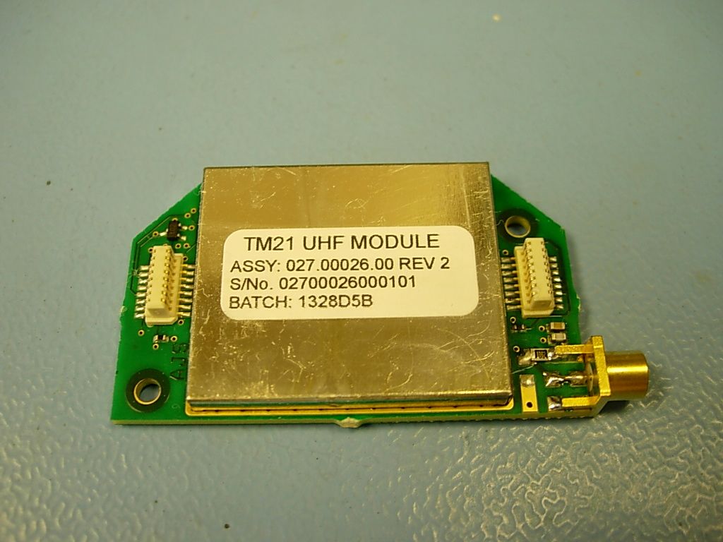
POSITION OF "LICENSE" LABEL MANUFACTURERS IDENTITY LABEL TM21 MODULE A B C D E F 1 2 3 4 FE D C B A 1 2 3 4 This drawing is the property of Datapaq Ltd. it is to be regarded as strictly confidential & is not to be reproduced in whole or part without written permission 3rd Angle Projection All parts to be free from burrs, sharp edges and corrosion General Finish DEB LICENSE LABEL POSITION Clean N/A - Specific Finish Material 11 Registered office - Deanland House , 160 Cowley Road , Cambridge , CB4 0GU , UK Registered in England No - 1777666 A4 Sheet size: Sheet of DATAPAQ LIMITED C • Linear - 1 decimal place ±0.20 - 2 decimal places ±0.10 • Angular ±0.5° • All dimensions in millimetres Unless otherwise stated General Tolerance Drawing Number ScaleDrawn Title REVISIONS DEB DPM A0 22Jun2010 Initial Draft 1:1 Notes, processes and assembly instructions: Do not scale from this drawing CAD CAM input data available on request (DXF, IGES) - Drn Chk Iss Issue Date Reason For Change
ID Label/Location Info
25 6 R1 Material :- Melinex reverse printed black characters on white background with Scotch 468 adhesive with "peel off" backing Characters 1.5mm or point equivalent in Swis format. A B C D E F 1 2 3 4 FE D C B A 1 2 3 4 This drawing is the property of Datapaq Ltd. it is to be regarded as strictly confidential & is not to be reproduced in whole or part without written permission 3rd Angle Projection All parts to be free from burrs, sharp edges and corrosion General Finish DEB MAN LABEL Clean SEE NOTES LB1470A Specific Finish Material 11 Registered office - Deanland House , 160 Cowley Road , Cambridge , CB4 0GU , UK Registered in England No - 1777666 A4 Sheet size: Sheet of DATAPAQ LIMITED C • Linear - 1 decimal place ±0.20 - 2 decimal places ±0.10 • Angular ±0.5° • All dimensions in millimetres Unless otherwise stated General Tolerance Drawing Number ScaleDrawn Title REVISIONS DEB DPM A0 22Jun2010 Initial Draft 1:1 Notes, processes and assembly instructions: Do not scale from this drawing CAD CAM input data available on request (DXF, IGES) - Drn Chk Iss Issue Date Reason For Change
Operational Description
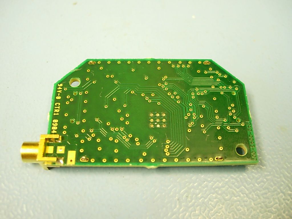
Deanland House 160 Cowley Road Cambridge CB4 0GU, UK. TM21 Transceiver Module – Operational Description The TM21 Module is a low power UHF transceiver, based on a single chip transceiver (Chipcon CC1020), which can be configured to operate in various frequency bands designated for SRD systems in the 402MHz to 470MHz range. It has been designed to provide data telemetry functionality to a range of temperature profiling data loggers. The TM21 module is used in the data logger to transmit data and in the receivers to receive data. The logger is classed as mobile equipment. The frequency band is configured during final assembly of the host equipment and is not configurable by the end user after this point other than to select channels in the pre-determined range. The Module has two connectors to interface to a host PCA. One connector carries power and the other carries all the communication and control lines. The Module is controlled over an I 2 C bus which passes data in both directions. The Module has a PIC microcontroller which acts as a data and command buffer and interface between the CC1020 and the host PCA. It translates the commands sent to the Module into register settings for the CC1020 and forwards on the send and received data in the appropriate format. The PIC also reads the Module temperature from an on-board Thermal Sensor. This data is then used to apply temperature correction to the RF frequency to maintain an accurate output frequency from the transmitter. The power supply required by the module is 3.3V. It does not regulate its power supply from a higher voltage source. The power supply is filtered and de-coupled as required in the Module. In transmit mode the CC1020 takes the data from the PIC and applies it to the carrier using 2-level FSK modulation and a data rate of 4800baud. The RF output then has some matching circuitry between the CC1020 and an RF switch which selects the RF In/Out Digital Communications In/Out (I 2 C bus) PIC Microcontroller CC1020 RF Transceiver Power In 8MHz XTAL 14.7456MHz XTAL Power Supply Filtering & Decoupling Low Pass RF Filter TM21 RF Transceiver Module Block Diagram of TM21 Transceiver Module Thermal Sensor RF O/P Matching RF I/P Matching RF Switch Deanland House 160 Cowley Road Cambridge CB4 0GU, UK. signal path for transmit or receive mode. Following the RF switch is a low pass filter before the MCX antenna socket. Each frame of data is split up into two packets typically with every 16 th frame being three packets long. It takes 120ms to transmit each packet of data with about 70ms between packets. The overall transmission duty cycle is determined by the sample rate selected by the user for the host data logger; this could be between 0.5 seconds between samples to several hours. The antenna used with the loggers for transmitting is a quarter wave monopole with a gain of 1.5dBd. The output power from the CC1020 is programmable and is set to 10dBm (10mW) maximum. A ramp profile is used when turning on and off the output power to reducing switching transients. In receive mode the signal passes through the low pass filter and then through the RF switch into the receiver matching circuitry and the CC1020 RF input. The CC1020 then locks to the signal and demodulates the data which it then passes on to the PIC. The data transmitted has error correction coded into it to improve the performance of the telemetry system. To improve the performance even more the data packets can be interleaved up to nine times. This means that the packet of data is resent the number of times selected with the subsequent packets of data so that if interference disrupts the reception of a packet one time it is likely to be received correctly the next time it is sent or the time after that, etc. In addition to this the user can opt to enable Listen before Transmit to prevent on air clashes of transmissions if there are multiple loggers being used. The user can select one of ten channels to use for their telemetry in order to avoid any interference that may be present. The host passes this channel information to the PIC which sets the channel by altering values in set-up registers in the CC1020 chip. The frequency range for the US and Canada is 463.525MHz to 463.975MHz. Although the module is capable of transmitting on other frequencies the user can only select the frequencies that were configured in the factory during the final test and calibration phase of the equipment manufacture.
RF Exposure Info
Deanland House 160 Cowley Road Cambridge CB4 0GU, UK. RF Exposure Statement for the Datapaq TM21 Transceiver Module FCC ID: YEETM21 The Datapaq TM21 Transceiver Module complies with the FCC limits for RF exposure as laid out in OET Bulletin 65. The TM21 Transceiver module is used in transmit mode at distances greater than 20cm from the user, in most cases considerably greater, therefore, it can be classified as a ‘Mobile Device’ for the purposes of RF exposure. It is not co-located with other transmitters when in operation so only the individual TM21 output need be considered. Although it is used in an industrial environment and not by the general public the more stringent limits for the General Public/Uncontrolled Use have been considered. These limits are f/1500 mW/cm 2 for frequencies between 300MHz and 1500MHz (where f is the frequency in MHz). The TM21 uses frequencies at around 464MHz which equates to 0.31mW/cm 2 . The output of the TM21 is 10mW with the maximum gain antenna specified for use with the system (monopole with ground plane; gain = 1.5dBd). The power density (PD) from a 10mW source at a distance (d) of 20cm can be calculated using the formula: PD = power / (4 * pi * d 2 ) where PD is in mW/cm 2 , power is in mW and distance is in cm. = 10 / (4 * 3.1416 * 400) = 0.002mW/cm 2 This value is well below the Maximum Permissible Exposure limit of 0.31mw/cm 2 . Finally, it is worth noting that the TM21 is not used in continuous transmit mode. It can transmit at a sample period of 0.5 seconds but would typically be used with longer sample periods than this. The transmit frame is typically two 120ms long bursts with about 70ms between them, but occasionally (every 16 frame) a third 120ms burst is added resulting in a transmission burst of about 0.5 seconds.
Test Report
|---------- ( Cambridge Ltd. ) ----------| Testing EMCEMC Consultancy EMC Training or : 01223 241140 (accounts) 23, Headington Drive, Cambridge. CB1 9HE Tel : 01954 251974 (test site) Fax : 01954 251907 email: [email protected] web : www.dbtechnology.co.uk REPORT ON ELECTROMAGNETIC COMPATIBILITY TESTS Performed at: TWENTY PENCE TEST SITE Twenty Pence Road, Cottenham, Cambridge U.K. CB24 8PS on Datapaq Ltd TM21 dated 25th May 2010 Document History DSAdd Rx spurious results25/05/102 Initial release12/05/101 Approved by Revised by Description of modifications Affected page(s) DateIssue Based on report template: v090319 1 of 34 Page: Test Report T3533 Test No: FCC ID: YEETM21 R2758 2 Report No: Issue No: This report shall not be reproduced except in full, without the written approval of: dB Technology (Cambridge) Ltd. Equipment Under Test (EUT):TM21 Test Commissioned by:Datapaq Ltd Deanland House 160 Cowley Road Cambridge Cambridgeshire CB4 0GU Representative:Ceri Grenyer Test Started:10th April 2010 Test Completed:24th May 2010 Test Engineer:Dave Smith Date of Report:25th May 2010 Written by:Dave SmithChecked by:Derek Barlow Signature:Signature: Date:25th May 2010Date:26th May 2010 dB Technology can only report on the specific unit(s) tested at its site. The responsibility for extrapolating this data to a product line lies solely with the manufacturer. 2 of 34 Page: Test Report T3533 Test No: FCC ID: YEETM21 R2758 2 Report No: Issue No: This report shall not be reproduced except in full, without the written approval of: dB Technology (Cambridge) Ltd. Test Results Summary CFR 47 Part 90: Private Land Mobile Radio Services RSS-119 Issue 9: Land Mobile and Fixed Radio Transmitters and Receivers Operating in the Frequency Range 27.41-960MHz RF Output PowerCFR 47 Part 90.217(b)<=120mWPASS CFR 47 Part 2.1046 RSS-119 5.4/5.10 Frequency StabilityCFR 47 Part 90.217(b)Sufficiently stable that EUT still PASS CFR 47 Part 2.1055compliant with spurious emissions RSS-119 5.3/5.10mask when frequency drift taken into account. Spurious Radiated Field StrengthCFR 47 Part 90.217(b)30dB below carrierPASS CFR 47 Part 2.1053for all frequencies 25kHz or more RSS-119 5.10from carrier Spurious Conducted on Antenna PortCFR 47 Part 90.217(b)30dB below carrierPASS CFR 47 Part 2.1051for all frequencies 25kHz or more RSS-119 5.10from carrier Occupied BandwidthCFR 47 Part 90.217(b)30dB below carrierPASS CFR 47 Part 2.1049for all frequencies 25kHz or more RSS-119 5.10from carrier Receiver SpuriousRSS-119 5.1RSS-GEN section 4.10 and 6PASS 3 of 34 Page: Test Report T3533 Test No: FCC ID: YEETM21 R2758 2 Report No: Issue No: This report shall not be reproduced except in full, without the written approval of: dB Technology (Cambridge) Ltd. Contents 34 PLOT 16 Radiated Emissions - Receive Mode - 3GHz to 6GHz ................................. 33 PLOT 15 Radiated Emissions - Receive Mode - 1GHz to 3GHz .................................. 32 PLOT 14 Radiated Emissions - Receive Mode - 250MHz to 1GHz ............................... 31 PLOT 13 Radiated Emissions - Receive Mode - 25MHz to 275MHz .............................. 30 PLOT 12 Occupied Bandwidth ............................................................ 29 PLOT 11 Spurious Radiated Emissions - Tx - 2GHz to 5GHz ................................... 28 PLOT 10 Spurious Radiated Emissions - Tx - 1GHz to 3GHz ................................... 27 PLOT 9 Spurious Radiated Emissions - Tx - Near carrier with 1kHz RBW ......................... 26 PLOT 8 Spurious Radiated Emissions - Tx - Near carrier with 120kHz RBW ....................... 25 PLOT 7 Spurious Radiated Emissions - Tx - 250MHz to 1GHz .................................. 24 PLOT 6 Spurious Radiated Emissions - Tx - 25MHz to 275MHz ................................. 23 PLOT 5 Spurious Antenna Conducted - 1GHz to 5GHz ........................................ 22 PLOT 4 Spurious Antenna Conducted - 250MHz to 1GHz ...................................... 21 PLOT 3 Spurious Antenna Conducted - 25MHz to 275MHz ..................................... 20 PLOT 2 Spurious Antenna Conducted - Near Carrier ......................................... 19 PLOT 1 RF Output Power - Antenna Conducted ............................................. 18 4.7 Receiver Radiated Emissions - Results ................................................... 17 4.6 Occupied Bandwidth - Results ........................................................... 16 4.5 Spurious Transmitter Emissions - Results ................................................. 15 4.4 Spurious Conducted Emissions - Results ................................................. 14 4.3 Frequency Stability - Results ............................................................ 13 4.2 Power ERP - Results .................................................................. 12 4.1 RF Output - Conducted Power- Results ................................................... 11 4 Test Results ............................................................................ 11 3.7 Receiver Radiated Emissions ............................................................ 10 3.6 Occupied Bandwidth ................................................................... 10 3.5 Spurious Radiated ..................................................................... 10 3.4 Spurious Conducted on Antenna Port ..................................................... 10 3.3 Frequency Stability ..................................................................... 10 3.2 RF Output - ERP ....................................................................... 10 3.1 RF Output - Conducted Power ........................................................... 10 3 Test Methods ........................................................................... 9 2 Test Equipment .......................................................................... 8 Photograph 3 Close-up of TM21 Module connected to Q18 Logger ................................ 7 Ph…
Text truncated - open the document above for the full version.
Test Setup Photos
Photograph 1 Radiated Spurious - Logger Upright Photograph 2 Radiated Spurious - Logger Flat 1 of 2 Page: Test Report Photos File T3533 Test No: FCC ID: YEETM21 R2758 1 Report No: Issue No: This report shall not be reproduced except in full, without the written approval of: dB Technology (Cambridge) Ltd. Photograph 3 Close-up of TM21 Module connected to Q18 Logger 2 of 2 Page: Test Report Photos File T3533 Test No: FCC ID: YEETM21 R2758 1 Report No: Issue No: This report shall not be reproduced except in full, without the written approval of: dB Technology (Cambridge) Ltd.
Contact Information
Applicant
Ceri Grenyer(Senior Electronics Engineer)
Test Firm
DB TechnologyDave Smith
Technical Specifications
| # | Rule Parts | Frequency Range | Power Output | Emission | Tolerance |
|---|---|---|---|---|---|
| 1 | 90.217(b) | 463.525 MHz - 463.975 MHz | 10.00 mW | 10K8F1D | 4.0000000000 ppm |