YEF18862PICOAMPPico Cell Amplifier
Shireen Inc.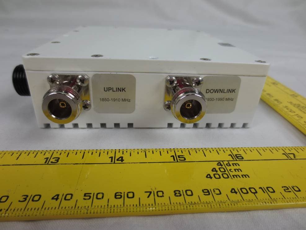
Click to zoom
Application Details
- Equipment Class
- B2I - Part 20 Industrial Booster (CMRS)
- Date of Grant
- Aug 20, 2015
- Application Purpose
- Original Equipment
- Date of Application
- Aug 20, 2015
- Equipment Note
- Pico Cell Amplifier
- Frequency Range
- 1850.00000000 - 1910.00000000
- Company
- Shireen Inc.
- Country
- United States
Documents & Files
Document Text
Text extracted from the exhibit documents filed with the FCC. Open a document above to read the original.
Users Manual
Pico Cell Amplifier User/ Installation Manual Model:Item#18-862 Copyright©2015Shireen Inc AllRightsReserved Reproduction,distributionorrevisionofpartorallofcontentsinthismanualinanyformwithoutwritten permissionofShireen Incisprohibited.Theinformationinthisguideissubjecttochangeduetofunction improvement,designalteration,etc.withoutanypriornotification. ShireenInc.12910 Cloverleaf Center Dr. Suite 110, Germantown, MD 20874Tel:301-838-4380 www.shireeninc.com Pico CellAmplifier# 18-862 ShireenInc.12910 Cloverleaf Center Dr. Suite 110, Germantown, MD 20874 Tel:301-838-4380www.shireeninc.com 2 SAFETY FIRST Foryoursafetyandtopreventinjurytotheinstallerortheoperator,installation must be handledby trained professionals only. Personalsafety: 1)Thisunitispoweredby28V DC power supply.Turnofftheelectricsupplyif youhavetodoanyrewiringorif you aremakingalterationstowall sockets. 2)Theequipmentshouldonlybeusedwith Pico Cell radio devices with RF power output of less than 1 Watt. 3) The unit is designed for installation on antenna tower or mast, which must only be done by fully trained personnel. WARNING. This is NOT a CONSUMER device. It is designed for installation by FCC LICENSEES and QUALIFIED INSTALLERS. You MUST have an FCC LICENSE or express consent of an FCC Licensee to operate this device. Unauthorized use may result in significant forfeiture penalties, including penalties in excess of $100,000 for each continuing violation RF Emissions Maximum Power Conducted: 40dBm Minimum distance between antenna and human:72cm Pico CellAmplifier# 18-862 ShireenInc.12910 Cloverleaf Center Dr. Suite 110, Germantown, MD 20874 Tel:301-838-4380www.shireeninc.com 3 TableofContents 1.General...............................................................................................4 2.PreparingtoinstallPico Cell Amplifier.................................................4 2.1.Overview..........................................................................4 2.2.Checkforsignalstrength.................................................4 2.3.CableRequirements........................................................4 2.4.PowerRequirements.......................................................4 3.Installation..............................................................................................5 3.1.Operatingtherepeater....................................................5 4.MaintenanceandTroubleshooting.....................................................5 Appendix A Specifications..........................................................................6 Appendix B BlockDiagram........................................................................ 7 Pico CellAmplifier# 18-862 ShireenInc.12910 Cloverleaf Center Dr. Suite 110, Germantown, MD 20874 Tel:301-838-4380www.shireeninc.com 4 1.General This Pico cell Amplifier increases RF signal powerfor uplink and downlinkof any Pico cell radio transceiver. Theoutdoor watertight unit can recover all cable losses and feeds full signal to theantenna feed for optimum signal. 2.PreparingtoinstallPico Cell Amplifier 2.1Overview Ideally,theamplifiershouldbeinstalled at the tower or mast near the antenna feed. This way all cable losses are recovered and full signal goes to the antenna. 2.2Checkforsignalstrength Most of the Picocell radios allow signal level setting. Typical radio power ranges between 0 thru 20dBm. Check the RF output settingof the unit before connectingto the amplifier. 2.3CableRequirements CoaxialcableisneededtoconnecttheItem#18-862with theantennasand the Pico cell radios.Forthebestperformance,cablesmustbelowloss.Shireen Inc is a leader in the RF cable Industry, please contact us for any custom lengths or specialized cable requirements. 2.4PowerRequirements This amplifier runs on 28V DC. Please use the power supply that was shipped with the unit. Other power supplies may not have enough amp to work with the amplifier WARNING This Pico Cell amplifierMUSTonlybeusedwiththeprovided poweradaptor.Useofotherpoweradaptorswillvoidthe warrantyandmaydamagetherepeater. Pico CellAmplifier# 18-862 ShireenInc.12910 Cloverleaf Center Dr. Suite 110, Germantown, MD 20874 Tel:301-838-4380www.shireeninc.com 5 3.0Installation: Theamplifiercanbeinstalledonaflatsurfacevia thru holes in the chassis with appropriate hardware. Run two coax cables from the Pico cell radioto the amplifier and connectto the appropriate uplink/downlink connectors.Run one cablefrom amplifier to the antenna. Connect thepower cable to the amplifier. Followtheantennainstallationproceduresas suggested by the antenna manufacture. 3.1Operatingthe Amplifier The amplifier can be powered up once all cables are connected and pico Cell radio is powered up. Follow the instructions of the Pico Cell radio to set theappropriateoutput power level. Once all items are properly connected and powered up, no user interface is necessary.. A glowing LED shows unit is powered up and operating. Warning Antenna Port of theamplifier mustbe connected to the antenna before power is turned on.. WARNING 4.MaintenanceandTroubleshooting: This Pico Cell amplifier is very robust unit and in most cases will last for years before needing any kind of troubleshooting. Some of the problems that can occur are: SymptomsCauseSolution No LEDPower failureCheck the power supply with Volt meter Enclosure Getting HotSignal input to the amplifier very high Log into the Pico cell radio software and reduce the power setting Call Qualityvery poorAmplifier in saturation due to high input Log into the Pico cell radio software and reduce the power setting You MUST operate thisdevice with approved antennas and cables as specified by the manufacturer. Antennas MUST be installed at least 72cm from any human. Pico CellAmplifier# 18-862 ShireenInc.12910 Cloverleaf Center Dr. Suite 110, Germantown, MD 20874 Tel:301-838-4380www.shireeninc.com 6 AppendixA Electrical Specifications: Frequency: Uplink:1850-1910 MHz Downlink:1930-1990 MHz Technology: CDMA/GSM,WCDMA, LT…
Text truncated - open the document above for the full version.
Attestation Statements
www.shireeninc.com 12910 Cloverleaf Center Dr. Suite 110, Germantown, MD 20874 Tel:301-838-4380 Fax: 301-576-8645 Attestation Letter FEDERAL COMMUNICATIONS COMMISSIONSJune 24th, 2015 Authorization and Evaluation Division 7435 Oakland Mills Road Columbia, MD 21046 Subject: Attestation letter regarding warning label FCC ID: YEF18862PICOAMP In accordance with KDB 935210 D02, section 4 (d), Shireen, Inc. hereby atteststhat the warning labelswill be permanently affixed to the unit, user manual and on outside packaging of the device. The warning labelwill be similar to the sample warning label below. Sincerely, Nusrat Jamal President / CEO
Cover Letter(s)
www.shireeninc.com 12910 Cloverleaf Center Dr. Suite 110, Germantown, MD 20874 Tel:301-838-4380 Fax: 301-576-8645 FCC Authorization FEDERAL COMMUNICATIONS COMMISSIONSApril 1, 2015 Authorization and Evaluation Division 7435 Oakland Mills Road Columbia, MD 21046 Subject: Agent Authorization FCC ID: YEF18862PICOAMP To whom it may concern: We, the undersigned, Hereby authorize Bay Area Compliance Laboratory Corporation to act on its behalf in all matters relating to application for Equipment authorization, including the signing of all documents relating to these matters. All acts carried out by Bay Area ComplianceLaboratory Corporation on our behalf shall have the same effect as our own action. We, the undersigned, hereby certify that we are not subject to a denial of federal benefits, that includes FCC benefits, pursuant to Section 5301 of the Anti-Drug Abuse Actof 1988, 21 U.S.C. 853(a). This authorization is valid until further written notice from the applicant. Sincerely Yours, Nusrat Jamal President / CEO
Cover Letter(s)
www.shireeninc.com 12910 Cloverleaf Center Dr. Suite 110, Germantown, MD20874 Tel:301-838-4380 Fax: 301-576-8645 Request forConfidentiality FEDERAL COMMUNICATIONS COMMISSIONSApril 1, 2015 Authorization and Evaluation Division 7435 Oakland Mills Road Columbia, MD 21046 Subject: Confidentiality Request regardingapplication for certification of FCC ID:YEF18862PICOAMP In accordance with Sections 0.457 and 0.459 of the Commission’s Rules,Shireen Inc.hereby requests long-term confidential treatment of information accompanying this application as outlined below: Schematics, Circuit Description Operation Description, Bill of material, and Test procedures The above materials contain proprietary and confidential information not customarily released to the public. The public disclosure of these materials provides unjustified benefits to its competitors in the market. Sincerely, Nusrat Jamal President / CEO
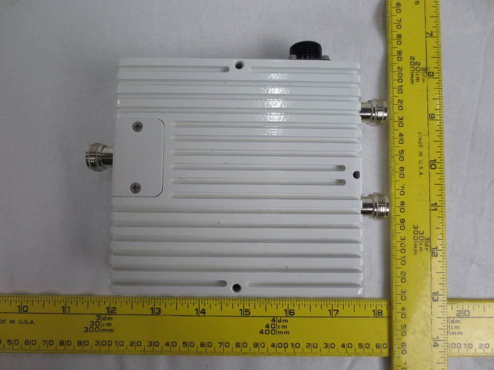
External Photos
Shireen, Inc. FCC ID: YEF18862PICOAMP; IC: 8987A-PICOAMP862 Report Number: R1503241-24 Page 102 of 105 FCC Part 24E/IC RSS-131 Test Report 13 Exhibit C – EUT Photographs 13.1 EUT – Front View 13.2 EUT – Rear View Shireen, Inc. FCC ID: YEF18862PICOAMP; IC: 8987A-PICOAMP862 Report Number: R1503241-24 Page 103 of 105 FCC Part 24E/IC RSS-131 Test Report 13.3 EUT – Right Side View 13.4 EUT – Left Side View Shireen, Inc. FCC ID: YEF18862PICOAMP; IC: 8987A-PICOAMP862 Report Number: R1503241-24 Page 104 of 105 FCC Part 24E/IC RSS-131 Test Report 13.5 EUT – Top View 13.6 EUT – Bottom View
Internal Photos
Shireen, Inc. FCC ID: YEF18862PICOAMP; IC: 8987A-PICOAMP862 Report Number: R1503241-24 Page 105 of 105 FCC Part 24E/IC RSS-131 Test Report 13.7 EUT – Open Case View 13.8 EUT – Open Case View- PCB Board Bottom --- END OF REPORT ---
RF Exposure Info
Shireen, Inc. FCC ID: YEF18862PICOAMP; IC: 8987A-PICOAMP862 Report Number: R1503241-24 Page 96 of 105 FCC Part 24E/IC RSS-131 Test Report 10 FCC §1.1307(b)(1), §2.1091 & IC RSS-102 - RF Exposure 10.1 Applicable Standards According to §1.1310 and §2.1091 (Mobile Devices) RF exposure is calculated. Limits for General Population/Uncontrolled Exposure Frequency Range (MHz) Electric Field Strength (V/m) Magnetic Field Strength (A/m) Power Density (mW/cm 2 ) Averaging Time (minute) Limits for General Population/Uncontrolled Exposure 0.3-1.34 614 1.63 *(100) 30 1.34-30 824/f 2.19/f *(180/f 2 ) 30 30-300 27.5 0.073 0.2 30 300-1500 / / f/1500 30 1500-100,000 / / 1.0 30 Note: f = frequency in MHz * = Plane-wave equivalent power density According to IC RSS-102 Issue 5 section 4, RF limits used for general public will be applied to the EUT. Shireen, Inc. FCC ID: YEF18862PICOAMP; IC: 8987A-PICOAMP862 Report Number: R1503241-24 Page 97 of 105 FCC Part 24E/IC RSS-131 Test Report 10.2 MPE Prediction Predication of MPE limit at a given distance, Equation from OET Bulletin 65, Edition 97-01 S = PG/4R² Where: S = power density P = power input to antenna G = power gain of the antenna in the direction of interest relative to an isotropic radiator R = distance to the center of radiation of the antenna 10.3 Test Results Downlink Maximum peak output power at antenna input terminal (dBm): 40.75 Maximum peak output power at antenna input terminal (mW): 11885.02 Prediction distance (cm): 72 Prediction frequency (MHz): 1960 Antenna Gain, typical (dBi): 4 Maximum Antenna Gain (numeric): 2.512 Power density at predication frequency and distance (mW/cm 2 ): 0.458 MPE limit for uncontrolled exposure at predication frequency (mW/cm 2 ): 1 Power density at predication frequency and distance (W/m2): 4.58 MPE limit for uncontrolled exposure at predication frequency (W/m2): 4.67 Uplink Maximum peak output power at antenna input terminal (dBm): 20.79 Maximum peak output power at antenna input terminal (mW): 119.95 Prediction distance (cm): 20 Prediction frequency (MHz): 1850.2 Antenna Gain, typical (dBi): 4 Maximum Antenna Gain (numeric): 2.512 Power density at predication frequency and distance (mW/cm 2 ): 0.05994 MPE limit for uncontrolled exposure at predication frequency (mW/cm 2 ): 1 Power density at predication frequency and distance (W/m2): 0.5994 MPE limit for uncontrolled exposure at predication frequency (W/m2): 4.48 Results For uplink and downlink, the highest power density levels at 72 cm are below the MPE uncontrolled exposure limit.
Test Report
Note: This test report is prepared for the customer shown above and for the device described herein. It may not be duplicated or used in part without prior written consent from Bay Area Compliance Laboratories Corp. This report must not be used by the customer to claim product certification, approval, or endorsement by A2LA* or any agency of the Federal Government. * This report may contain data that are not covered by the A2LA accreditation and are marked with an asterisk “*” (Rev.3) FCC PART 20.21, 24E IC RSS-131, ISSUE 2 TEST AND MEASUREMENT REPORT For Shireen, Inc. 12910 Cloverleaf Center Drive, Suite 110, Germantown, MD 20874, USA FCC ID: YEF18862PICOAMP IC: 8987A-PICOAMP862 Report Type: Original Report Product Type: 1900 MHz Picocell Amplifier Prepared By: Ronak Patel Test Engineer Report Number: R1503241-24 Report Date: 2015-08-14 Reviewed By: Simon Ma Test Engineer Bay Area Compliance Laboratories Corp. 1274 Anvilwood Avenue, Sunnyvale, CA 94089, USA Tel: 1 (408) 732-9162 Fax: 1 (408) 732-9164 Shireen, Inc. FCC ID: YEF18862PICOAMP; IC: 8987A-PICOAMP862 Report Number: R1503241-24 Page 2 of 105 FCC Part 24E/IC RSS-131 Test Report TABLE OF CONTENTS 1 GENERAL INFORMATION ............................................................................................................................... 5 1.1 PRODUCT DESCRIPTION FOR EQUIPMENT UNDER TEST (EUT) ........................................................................... 5 1.2 MECHANICAL DESCRIPTION .............................................................................................................................. 5 1.3 OBJECTIVE ......................................................................................................................................................... 5 1.4 RELATED SUBMITTAL(S)/GRANT(S) ................................................................................................................... 5 1.5 TEST METHODOLOGY ........................................................................................................................................ 5 1.6 MEASUREMENT UNCERTAINTY .......................................................................................................................... 6 1.7 TEST FACILITY ................................................................................................................................................... 6 2 SYSTEM TEST CONFIGURATION .................................................................................................................. 8 2.1 JUSTIFICATION ................................................................................................................................................... 8 2.2 EUT EXERCISE SOFTWARE ................................................................................................................................ 8 2.3 EQUIPMENT MODIFICATIONS ............................................................................................................................. 8 2.4 EUT INTERNAL CONFIGURATION ...................................................................................................................... 8 2.5 LOCAL SUPPORT EQUIPMENT LIST AND DETAILS .............................................................................................. 8 2.6 POWER SUPPLY AND LINE FILTERS .................................................................................................................... 8 2.7 INTERFACE PORTS AND CABLING ...................................................................................................................... 8 3 SUMMARY OF TEST RESULTS ........................................................................................................................ 9 4 FCC §2.1046, §24.232 & IC RSS-131 §4.3 - RF OUTPUT POWER ............................................................... 10 4.1 APPLICABLE STANDARDS ................................................................................................................................ 10 4.2 TEST PROCEDURE ............................................................................................................................................ 10 4.3 TEST EQUIPMENT LIST AND DETAILS .............................................................................................................. 11 4.4 TEST ENVIRONMENTAL CONDITIONS ............................................................................................................... 11 4.5 TEST RESULTS ................................................................................................................................................. 11 5 FCC §2.1049, §24.238 & IC RSS-GEN §6.6 - OCCUPIED BANDWIDTH .................................................... 16 5.1 APPLICABLE STANDARDS ................................................................................................................................ 16 5.2 TEST PROCEDURE ............................................................................................................................................ 16 5.3 TEST EQUIPMENT LIST AND DETAILS .............................................................................................................. 16 5.4 TEST ENVIRONMENTAL CONDITIONS ............................................................................................................... 16 5.5 TEST RESULTS ................................................................................................................................................. 17 6 FCC §2.1053, §24.238 & IC RSS-131§6.4 - SPURIOUS RADIATED EMISSIONS ...................................... 46 6.1 APPLICABLE STANDARDS ................................................................................................................................ 46 6.2 TEST PROCEDURE ...........................................................................................................…
Text truncated - open the document above for the full version.
Test Setup Photos
Shireen, Inc. FCC ID: YEF18862PICOAMP; IC: 8987A-PICOAMP862 Report Number: R1503241-24 Page 100 of 105 FCC Part 24E/IC RSS-131 Test Report 12 Exhibit B - EUT Setup Photographs 12.1 Radiated Emission below 1 GHz Front View at 3 Meters 12.2 Radiated Emission below 1 GHz Rear View at 3 Meters Shireen, Inc. FCC ID: YEF18862PICOAMP; IC: 8987A-PICOAMP862 Report Number: R1503241-24 Page 101 of 105 FCC Part 24E/IC RSS-131 Test Report 12.3 Radiated Emission above 1 GHz Front View at 3 Meters 12.4 Radiated Emission above 1 GHz Rear View at 3 Meters
Contact Information
Applicant
Nusrat Jamal(President)
Test Firm
Bay Area Compliance Laboratories Corp.Lisa Tang
Technical Specifications
| # | Rule Parts | Frequency Range | Power Output | Emission | Tolerance |
|---|---|---|---|---|---|
| 8 | 24E | 1.85 GHz - 1.91 GHz | 149.00 mW | D7W | Amp |
Other Applications from Shireen Inc.
YEF18892PICOAMP
Jul 28, 2015Pico Cell Amplifier
Equipment Class
B2I - Part 20 Industrial Booster (CMRS)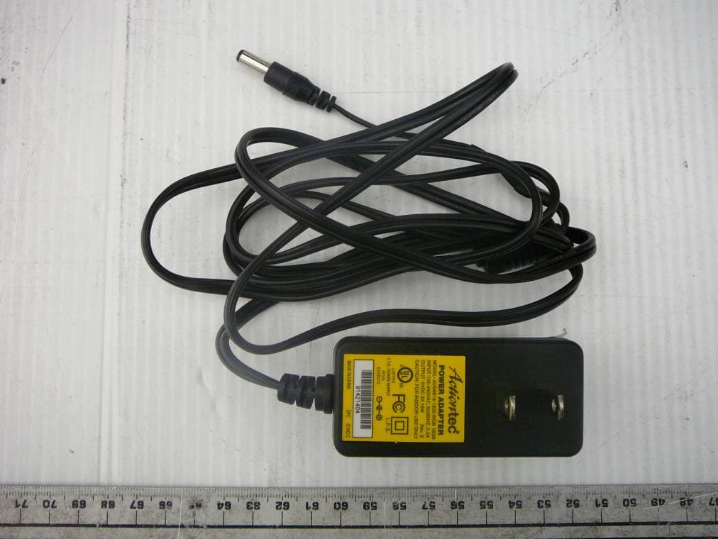
YEF18850-8001900
Oct 14, 2010Cellular Repeater Amplifier
Equipment Class
AMP - Amplifier
YEF18852-60-800
Jun 06, 2010Cellular Repeater Amplifier
Equipment Class
AMP - Amplifier