YF7WITURA2009GSM Remote Monitoring, Control and alarm system
Witura corporation sdn bhd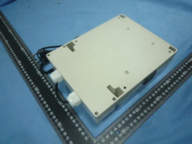
Click to zoom
Application Details
- Equipment Class
- PCT - PCS Licensed Transmitter worn on body
- Date of Grant
- May 26, 2010
- Application Purpose
- Original Equipment
- Date of Application
- May 26, 2010
- Equipment Note
- GSM Remote Monitoring, Control and alarm system
- Frequency Range
- 1850.20000000 - 1909.80000000
- Company
- Witura corporation sdn bhd
- Country
- Malaysia
Documents & Files
Document Text
Text extracted from the exhibit documents filed with the FCC. Open a document above to read the original.
Users Manual
WT-2009 IP65 GSM-AUTO WT-2009 IP65 GSM-AUTO – USER MANUAL – Rev. 1.0 WT-2009 GSM-AUTO User Manual IMPORTANT! Please read through the instruction manual before you start to install and program the device. If you are unsure how to connect the device you wish to control please refer to a qualified person. Description: The WT-2009 is a wireless remote control ON/OFF switch that connects to the GSM cell phone network. It is activated by calling its cell phone number, it will reject the call without answering and switch on the device connected to it. There are no call charges incurred when dialing the unit, it will recognize an authorized telephone number calling it and reject the call without answering. It has 2 independent switches, these can be programmed to switch on for a pre-determined length of time whenever the WT-2009 is called, alternatively the switches can be permanently switched ON or OFF by sending the WT-2009 a text message. WT-2009 IP65 GSM-AUTO WT-2009 IP65 GSM-AUTO – USER MANUAL – Rev. 1.0 Requirements: - The WT-2009 requires a 12 volt DC power supply capable of providing a minimum current of 500mA, typical current consumption is 50mA - A mobile phone SIM card with sufficient credit to send confirmation text messages when programming the WT-2009 unit. Installation: Insert the SIM card, to access the SIM card carrier gently push the button adjacent to it, insert the SIM card and carefully close the carrier, connect the antenna Connect a 12 volt DC power supply to terminal 1 & 2 ensuring positive is connected to terminal 1, switch on the power supply, the power LED will lit indicating power is present, the network LED indicator will initially flash quickly, once logged onto the network it will flash more slowly approximately every 3 to 4 seconds It is recommended that the WT-2009 be programmed to operate as required before final installation WT-2009 IP65 GSM-AUTO WT-2009 IP65 GSM-AUTO – USER MANUAL – Rev. 1.0 Connection Details: If you are unsure how to connect the device you wish to control please refer to a qualified person. Port Descriptions 1 +12 volts 2 - 12 volts 12 volt DC power supply capable of providing a minimum current of 1 Amp 3 COMMON (COM) 4 NORMALLY CLOSED (N.C) 5 NORMALLY OPEN (N.O) RELAY 2 6 NORMALLY CLOSED (N.C) 7 NORMALLY OPEN (N.O) 8 COMMON (COM) RELAY 1 Example Connections HEATER 110V ac LIGHT 110V ac 1 2 3 4 5 6 7 8 + - C NC NO NC NO C 12V DC RELAY 2 RELAY 1 A heater connected to relay 2 and a light to relay 1 When the WT-2009 is activated the relay contact will switch from the NC position to the NO position thus making the circuit and the heater and light will be switched on WT-2009 IP65 GSM-AUTO WT-2009 IP65 GSM-AUTO – USER MANUAL – Rev. 1.0 Default Settings The default settings are, open access mode*, when activated relay 1 on for 2 seconds, wait time of 2 seconds, relay 2 on for 2 seconds, the default password is 123456 * Any call to the WT-2009 will activate it Programming the WT-2009 The WT-2009 is programmed by sending it SMS text commands from a mobile phone, these are sent to the telephone number of the SIM card installed in the WT-2009. The password command must pre-fix all SMS text commands it is recommended the default password be changed. Remember that all SMS text commands must always be sent in CAPITAL LETTERS DO NOT add spaces or any other characters Programming Commands If you are familiar with the commands a quick reference can be found on page 10 #PWD Password This command must always pre-fix any SMS text commands to the unit using the 6 digits as a password. The unit comes from the factory with the default password set as 123456 and the following must pre-fix all commands to the unit #PWD123456 of course when you change the password you will pre-fix all commands with the new password TO GATE CONTROL PANEL SAFETY CONNECTION TO GATE CONTROL PANEL ‘START’ BUTTON CONNECTION Connections to an automatic gate control panel relay 1 control the opening of the gate relay 2 can be activated to ensure the gate remains open, for example a factory may want to leave the gate open during the day for easy access. (Note relay 1 would be connected in series with existing safety devices) WT-2009 IP65 GSM-AUTO WT-2009 IP65 GSM-AUTO – USER MANUAL – Rev. 1.0 #CAP Changing the Password To change the password of the unit you would use the #CAP Command and to change the password to 121212 you would send the following SMS text message to the unit. #PWD123456#CAP121212#CAP121212 the #CAP121212 is sent twice as confirmation of the new password. You will receive the following confirmation from the unit #CAP_OK #WHL White List This is the command that you will use for adding the authorized telephone numbers that can access the system. The system comes in the open access mode which allows any telephone number to access the system and once the system has been installed and the White list programmed you would secure the system using the #ACM2 command. To add a number to the white list, you would send the following SMS text message to the unit assuming the number would be 07827829595. Always remember to only use the last 8 digits of the telephone number. #PWD121212#WHL01=27829595 You will receive the following confirmation from the unit #WHL01_OK This is the first number in the White list and number 2 is sent as #WHL02= and so on up to a maximum of 99 numbers, number 99 would be #WHL99= Checking the number in the White list To check the number in a position on the white list, for example position 01 you would send the following SMS text message to the unit #PWD123456#WHL01? You will receive the following confirmation from the unit #WHL01=27829595 Erasing a number in the White list To erase a number in the white list you would send the following SMS text message to the unit. #PWD121212#WHL01D You will receive the following confirmation from the unit #WHL01_OK Erasing all the number in the White list To erase all the numbers in the white list you would send the following …
Text truncated - open the document above for the full version.
Block Diagram
Power Supply MC29302bt 78L05 DC 15 to 24V DC 12V Regulators DC Header LM2596 DC 4.2V RegulatorsDC 5V Regulators GSM Module SIM300 GSM ANT900-1800MHz 2.5dB SIM Card GSM Net Indicator LED Blue SCM STC89C516RD+ Relay1Relay2 DC 12V Control DC 12V Control CommunicateUart TTL 232 Communicate Power Supply 3V IIC BUS 24C128 +12VGND +4.2VSGND +5VSGND Drive +12VSGND Drive TTLTTL TTL Relay1 Run Indicator LED Green LED TTL TTL MGND TXD RXD MGNDAGND HC4052 PC Program Header Drive SGND +5V +5V+5V +5V +5V +5V Power Indicator LED Red +5VSGND Gsm Power Key Crystal24MHz RESET +12VGND Company Name Version V1.0 Data 2010-05-18 维特徕通信设备有限公司 Drawing name WT-2009 Block diagram
Cover Letter(s)
Witura Corporation Sdn bhd Add: 101-12-03 & 04, Menara Perdana, Jalan Gurdwara, 10300 Penang, Malaysia (5- 22, 2010) To: SIEMIC, INC. 2206 Ringwood Avenue, San Jose, CA 95131 USA Dear Sir/Madam, Re: Project and Product Certification Representative Authorization Letter We, Witura Corporation Sdn bhd hereby authorize SIEMIC, INC. to act as a Certification Body for certifying for the following project(s): (Product description, model name) FCC ID: YF7WITURA2009 Product name: GSM Remote Monitoring, Control and alarm system Model: WT-2009,WT-9001,WT-9002,WT-009,WT-215, WT-211,WT-1041,WT-1021,WT- 1010,WT-1018 ,WT-1011 We affirm that between SIEMIC and Witura Corporation Sdn bhd , any difference in understanding, including test plan, measurement methods, applicable standards and relevant procedures and processes have been resolved prior to commencement of testing activities. Sincerely, Signature: William Chin / Manager Title: Manager Telephone: +604-2289053 Email: [email protected] Date: 5-- 22, 2010 Witura Corporation Sdn bhd
External Photos
Report No.: ATS10051712 FCC ID: YF7WITURA2009 Page 36 of 38 12. Photos of EUT
ID Label/Location Info
FCC ID: YF7WITURA2009 Model No.: WT-2009 Manufacturer:ShenZhen Witura Telecommunications Co.,Ltd.
ID Label/Location Info
Label location
Internal Photos
Report No.: ATS10051712 FCC ID: YF7WITURA2009 Page 37 of 38 Report No.: ATS10051712 FCC ID: YF7WITURA2009 Page 38 of 38 END OF REPORT
Operational Description
The WT-2009 is a wireless remote control ON/OFF switch that connects to the GSM cell phone network. It is activated by calling its cell phone number, it will reject the call without answering and switch on the device connected to it. There are no call charges incurred when dialing the unit, it will recognize an authorized telephone number calling it and reject the call without answering. It has 2 independent switches, these can be programmed to switch on for a pre-determined length of time whenever the WT-2009 is called, alternatively the switches can be permanently switched ON or OFF by sending the WT-2009 a text message. 1: External 12V DC power supply, stabilizing the +12 V through the LM2596 voltage relay provides voltage to 12V. Stability through the +5 V +12 V voltage supply for the CPU. MIC29302 stability by a +4.2 V supply voltage for the SIM300. 2: CPU and SIM300 through TXD RXD connection between the communication protocol is RS232 protocol, in order to achieve and read the contents of incoming SMS phone number. 3: CPU IO to control through two relays open and close
Parts List/Tune Up Info
Witura Corporation Sdn bhd Add: 101-12-03 & 04, Menara Perdana, Jalan Gurdwara, 10300 Penang, Malaysia Letter of Certification This is to formally certify that: The tune up procedures of GSM Remote Monitoring, Control and alarm system (Model WT-2009, WT-9001, WT-9002, WT-009, WT-215, WT-211,WT-1041,WT-1021,WT-1010,WT-1018 ,WT-1011) is not open to end user. The end user is not allowed to perform final tune. All the power and frequency set up were finished at the manufacturer stage. Signature: William Chin / Manager Title: Manager Telephone: +604-2289053 Email: [email protected] Date: 5-- 22, 2010 Witura Corporation Sdn bhd
Parts List/Tune Up Info
Issued By:liu Document No: Checked By: Issue Date:2009.1.2 Serialnum bername Type param eerror Package sdosage Component codenote 1 resistor_SMD0R±5%M08052R7R8±5% 2resistor_SMD100K±5%M08051R15±5% 3resistor_SMD100K±5%M08051R2±5% 4resistor_SMD10K±5%M08056R1R3R9 R17 R19±5% R20 5resistor_SMD1K±5%M08052R4R6±5% 6resistor_SMD3.3K±5%M08052R18R21±5% 7resistor_SMD3.3r±5%M08051R10±5% 8resistor_SMD43K±5%M08051R13±5% 9resistor_SMD47K±5%M08052R11R12±5% 10resistor_SMD5.1K±5%M08053R5R14 R16±5% 11resistor_SMD103±10%M08052C5C6±10% 12resistor_SMD106±10%M08051C2±10% 13resistor_SMD152±10%M08051C4±10% 14resistor_SMD27PM08052C7C8 15resistor_SMD68UHTPDG-12.1*11L1 16transistor_SMD8050SOT232Q2Q3 17transistor_SMD9013SOT231Q1 18transistor_SMDIN5819DISEO-M42D6D9 19IC_SMDLM2596 ADJTO-263-5T1U2ADJ 20IC_SMDHCF4052SOJ-161U7 21IC_SMDMC29302BTTO-263-5T1U1 Don't stick the wrong location coding repetition 22IC_SMD24C128SOP81U5 23IC_SMD78L05SOT-891U6 24Seat moduleSIM300SIM3001U3 25gets stuck_SIMSIMCARDB-PJSIMCA*81U4 26seatIcSTC89C516MPLCC44-N1U1 Don't stick the wrong location coding repetition 27 Plug-in electrolytic capacitors330U/25VC2-82 C3C9 Plug-in component a: Patch components Slide groove BILL OF MATERIAL (Item list of materials) Revision:V1.3 Model No: WT2009 V1.2 Product Name:WT-2009 27 Plug-in electrolytic capacitors470UF/35VC2-81 C1 27 Plug-in electrolytic capacitors2200UF/16VC2-81 C10 27 Plug-in electrolytic capacitors27V/1WDIODE0.51 D5voltage27v/1W 27 Plug-in electrolytic capacitors5.1V/0.5WDIODE0.51 D8voltage5.1v/0.5W 27 Plug-in electrolytic capacitors4.7V/0.5WDIODE0.51 D10voltage4.7v/0.5W 34relayJQX-15F(T90)2 K1K2 12VDC(6 feet)NO:30A NC:20A 240VAC/28VDC 35PIN PINC0N3SIP31 J1 Black 3PIN insert needle, 36Wiring seat300V10A4.9*2NIP4 S2S3S4 S5 Blue 2NIP combined 300V10A 37 Wiring seatSW-SPSTHD21 S1 38crystals24MHZCRYSTAL1 Y1 39LED_LampLEDLED3 D11D12 D7 D11 red, green, blue D7. D12 and highlight, starting 40switchSW SPSTSW31 S17 Single dial switch Use screws 41 Shell wiring8PIN1 With 8INP enclosure In a circle 42 The bronze pillars3*5mm3Support board 43ScrewΦ1.9*45 The bronze pillars supporting the use of 44 LED_lampshadeΦ6.3*6.8mm3LED_Leds
RF Exposure Info
Page 1 of 2 FCC ID: YF7WITURA2009 RF Exposure Statement 1 The Reqirement: Systems operating under the provisions of this section shall be operated in a manner that ensures that the public is not exposed to radio frequency energy levels in excess limit for maximum permissible exposure. In accordance with 47 CFR FCC Part 2 Subpart J, section 2.1091 this device has been defined as a mobile device whereby a distance of 0.2 m normally can be maintained between the user and the device . 2 The procedures / limit : (A) Limits for Occupational / Controlled Exposure Frequency Range (MHz) Electric Field Strength (E) (V/m) Magnetic Field Strength (H) (A/m) Power Density (S) (mW/ cm 2 ) Averaging Time |E| 2 ,|H| 2 or S (minutes) 0.3-3.0 6141.63(100)* 6 3.0-30 1842 / f4.89 / f(900 / f)* 6 30-300 61.40.1631.0 6 300-1500 F/300 6 1500-100,000 5 6 (B) Limits for General Population / Uncontrolled Exposure Frequency Range (MHz) Electric Field Strength (E) (V/m) Magnetic Field Strength (H) (A/m) Power Density (S) (mW/ cm 2 ) Averaging Time |E| 2 ,|H| 2 or S (minutes) 0.3-1.34 6141.63(100)* 30 1.34-30 824/f2.19/f(180/f)* 30 30-300 27.50.0730.2 30 300-1500 F/1500 30 1500-100,000 1.0 30 Note: f = frequency in MHz ; *Plane-wave equivalent power density Page 2 of 2 FCC ID: YF7WITURA2009 3 MPE Calculation Method E = Electric field (V/m) P = Peak RF output power (mW) G = EUT Antenna numeric gain (numeric)= d = Separation distance between radiator and human body (m) The formula can be changed to We can change the formula to: From the peak EUT RF output power, the minimum mobile separation distance, d=0.2m, as well as the gain of the used antenna, the RF power density can be obtained GSM 850: Antenna Gain (dBi) Antenna Gain (numeric) Peak Output Power (dBm) Peak Output Power (mW) Power Density (S) (mW/cm2) Limit of Power Density (S) (mW/cm2) Test Result 2.5 1.78 30.821207.8140.427701 0.549 Complies 2.5 1.78 30.711177.6160.417004 0.557 Complies 2.5 1.78 30.681169.4990.414133 0.565 Complies PCS 1900: Antenna Gain (dBi) Antenna Gain (numeric) Peak Output Power (dBm) Peak Output Power (mW) Power Density (S) (mW/cm2) Limit of Power Density (S) (mW/cm2) Test Result 2.5 1.78 28.24666.8070.236124 1 Complies 2.5 1.78 28.17656.1450.232349 1 Complies 2.5 1.78 28.29674.5280.238858 1 Complies NOTE:
Schematics
R103R3 C5103 MGND MGND vbat(4.2v) vbat(4.2v) NET-LED MGND MGND VBAT 1 VBAT 2 VBAT 3 VBAT 4 VBAT 5 VBAT 6 VBAT 7 VBAT 8 GND 9 GND 10 GND 11 GND 12 GND 13 GND 14 VRTC 15 SIM_PRE 16 VDD_EXT 17 SPI_DATA 18 SIM_VDD 19 SPI_CLK 20 SIM_I/O 21 SPI_CS 22 SIM_CLK 23 SPI_D/C 24 SIM_RST 25 SPI_RST 26 NETWOR 30 PWRKEY 34 RXD 40 TXD 42 RTS 44 RI 48 AGND 50 AGND 51 MIC1P 53 SPK1P 54 MIC1N 55 SPK1N 56 BBP 36 U3 SIM300 PWRKEY RING2 I/O 3 VPP 2 GND 1 VCC 6 RST 5 CLK 4 U4SIMCARDB-PJ TXD_1 AGND MGND MGND dc24v Vin 1 on/off 5 Vout 2 gnd 3 gnd 4 U2LM2596 C4 152 C3 330u/25v L168uH SGND SGND SGND dc12v SGND R3 10K R41K SGND D8 5.1V/0.5W SGND S1SW SPST D5 27V SGND C1 470/36V dc24v P4.2 1 P1.0/T2 2 P1.1/T2EX 3 P1.2 4 P1.3/SPWM0 5 P1.4/SPWM1 6 SPWM2/P1.5 7 SPWM3/P1.6 8 SPWM4/P1.7 9 RES 10 RXD/P3.0 11 P4.3 12 TXD/P3.1 13 #INT0/P3.2 14 #INT1/P3.3 15 T0/P3.4 16 T1/P3.5 17 #WR/P3.6 18 #RD/P3.7 19 XTAL2 20 XTAL1 21 VSS 22 P4.0 23 A8/P2.0 24 A9/P2.1 25 A10/P2.2 26 A11/P2.3 27 A12/P2.4 28 P2.5/A13 29 P2.6/A14 30 P2.7/A15 31 #PSEN 32 ALE 33 P4.1 34 #EA 35 P0.7/AD7 36 P0.6/AD6 37 P0.5/AD5 38 P0.4/AD4 39 P0.3/AD3 40 P0.2/AD2 41 P0.1/AD1 42 P0.0/AD0 43 VDD 44 U1 STC89C516 D9 IN5819 C9 330u/25v SGND VCCA VCCA D10 4.7V/0.5W 1 2 3 4 5 5 U1mc29302bt 5 + C10 2200U/16V vbat(4.2v) R13 43k R2 100k MGND dc12v C827PC727P Y124MHZ SGND R110K C2 106 +5V SGND RST + RST 123 J1CON3 RXD_CPUTXD_CPU SGND RXD_CPUTXD_CPU A0 1 A1 2 A2 3 GND 4 SDA 5 SCL 6 WP 7 VCC 8 U5 24C128 +5V SGND C6103 +5V SGND R1247K R11 47K SCL SDA SDA SCL PWRKEY RING2 RXD_CPU +5V 0Y 1 2Y 2 Y-COM 3 3Y 4 1Y 5 INH 6 VEE 7 VSS 8 B 9 A 10 3X 11 0X 12 X-COM 13 1X 14 2X 15 VDD 16 U7 4052 SGND SGND A_1 R1910K TXD_CPUTXD_2 TXD_1 TELP_OUT SGND R18 3.3K Q28050 R1710K +5V TELP_OUT 2 41 56 K1 RELAY-DPDT1 2 41 56 K2 RELAY dc12v dc12v SGND dc12v +5V R15100K R55.1K SGND NET-LED Q19013 R65.1K 2 1 D7 LED +5V +5V R145.1K 21 D11 REDLED SGND R7 0R SGND AGND R8 0R SGND MGND A_1 +5V R165.1K 21 D12LED TEL_LED TEL_LED TELP_OUT1 SGND R21 3.3K Q38050 R2010K +5V TELP_OUT1 SGND Vin 1 GND 2 Vout 3 U678L05 R910K 12345678 JP18 HEADER IN+V220OFF1NO2IN1+V220NO1OFF2 IN+V220 OFF1 NO2 IN1+V220 NO1 OFF2 SGND D6IN5819 XTAL1XTAL2 XTAL1XTAL2 Power Cell Circuit GSM Cell Circuit MCU Cell Circuit Relay Cell Circuit IIC Uart Cell Circuit GSM ANT 3.5 dB NET LED Company Name Version V1.0 Data 2010-05-18 维特徕通信设备有限公司 Drawing name WT-2009 Schematic
Test Report
Name: Asia Technology Service Limited Address:1/F, A Building, Hao-yu Industrial Park, Qi-Feng road DongGuan, 523001, China FCC ID: YF7WITURA2009 Page 1 of 38 TEST REPORT FCC ID: YF7WITURA2009 Applicant:Witura Corporation Sdn bhd Address : 101-12-03 & 04, Menara Perdana, Jalan Gurdwara, 10300 Penang, Malaysia Equipment Under Test(EUT): Name : GSM Remote Monitoring, Control and alarm system Model : WT-2009,WT-9001,WT-9002,WT-009,WT-215, WT-211,WT-1041,WT-1021,WT-1010,WT-1018 , WT-1011 In Accordance with: FCC PART 2; FCC PART 22H; FCC PART 24E Report No : ATS10051712 Date of Test : May 17---19, 2010 Date of Issue : May 21, 2010 Test Result: PA S S In the configuration tested, the EUT complied with the standards specified above Authorized Signature ___________________________ (Bruce) General Manager The manufacture should ensure that all the products in series production are in conformity with the product sample detailed in this report. If the product in this report is used in any configuration other than that detailed in the report, the manufacturer must ensure the new system complies with all relevant standards. Any mention of Asia Technology Service Limited. Or test done by Asia Technology Service Limited. Approvals in connection with, distribution or use of the product described in this report must be approved by Asia Technology Service Limited. Approvals in writing. Report No.: ATS10051712 FCC ID: YF7WITURA2009 Page 2 of 38 Contents 1. General Information ...............................................................................................................4 1.1. Description of Device (EUT) ..........................................................................................4 1.2. Test Lab information .......................................................................................................4 2. Summary of test ......................................................................................................................5 2.1. Summary of test result ....................................................................................................5 2.2. Assistant equipment used for test....................................................................................5 2.3. Test mode ........................................................................................................................6 2.4. Test Environment Conditions..........................................................................................6 2.5. Measurement Uncertainty (95% confidence levels, k=2) ...............................................6 2.6. Test Equipment ...............................................................................................................7 3. Conducted Output power .......................................................................................................8 3.1. Block Diagram of Test Setup ..........................................................................................8 3.2. Limit................................................................................................................................8 3.3. Test Procedure.................................................................................................................8 3.4. Test Result.......................................................................................................................8 4. POWER LINE CONDUCTED EMISSION .........................................................................9 4.1. Conducted Emission Limits(15.209&249) .....................................................................9 4.2. Test Setup........................................................................................................................9 4.3. Test Procedure...............................................................................................................10 4.4. Test Resluts ...................................................................................................................10 5. Radiated Output power ........................................................................................................12 5.1. Block Diagram of Test Setup ........................................................................................12 5.2. Limit..............................................................................................................................12 5.3. Test Procedure...............................................................................................................12 5.4. Test Result.....................................................................................................................13 6. Occupied Bandwidth ............................................................................................................14 6.1. B lock Diagram of Test Setup .......................................................................................14 6.2. Limit..............................................................................................................................14 6.3. Test Procedure...............................................................................................................14 6.4. Test Result.....................................................................................................................15 6.5. Orginal test data ............................................................................................................15 7. Frequency stability................................................................................................................19 7.1. Block Diagram of Test Setup ........................................................................................19 7.2. Limit..............................................................................................................................19 7.3. Test Procedure..............................................................................…
Text truncated - open the document above for the full version.
Test Setup Photos
Report No.: ATS10051712 FCC ID: YF7WITURA2009 Page 35 of 38 11. Testsetup photo
Contact Information
Applicant
William Chin(Manger)
Test Firm
Asia Technology Service LimitedBruce Yang
[email protected]0769-8204556
Technical Specifications
| # | Rule Parts | Frequency Range | Power Output | Emission | Tolerance |
|---|---|---|---|---|---|
| 2 | 24E | 1.85 GHz - 1.91 GHz | 1.2 W | 315KGXW | 0.021 ppm |